


Serviços Personalizados
Artigo
 Inglês (pdf)
 Artigo em XML
 Referências do artigo
Indicadores

Links relacionados
-
 Citado por Google
 -
 Similares em Google
Compartilhar

 Permalink
Journal of the South African Institution of Civil Engineering
versão On-line ISSN 2309-8775
versão impressa ISSN 1021-2019
J. S. Afr. Inst. Civ. Eng. vol.62 no.2 Midrand Jun. 2020
http://dx.doi.org/10.17159/2309-8775/2020/v62n2a1
TECHNICAL PAPER
http://dx.doi.org/10.17159/2309-8775/2020/v62n2a1
Mechanical behaviour of semi-rigid connections coupling two concrete segmental linings
P Zhai; P Xu
ABSTRACT
This paper describes the use of segment joints in shield-driven tunnel linings. The opening of segment joints due to the application of a bending moment under different levels of axial stress is studied. The main focus is the mechanical behaviour of the joints, which are considered to be semi-rigid, and the moment-rotation behaviour of the joint. A physically based mathematical model is proposed based on the joint dimensions and material properties. Considering joints connected by two long curved bolts as an example, the model parameters are evaluated, and the moment-rotation curves for the joint are presented. The model distinguishes joint behaviour before and after opening, and agrees well with the real mechanical behaviour of the joints. A comparison with previous experiments on segment joints and with Janssen's and Gladwell's models is provided, and the proposed model is found to be accurate and universal.
Keywords: shield-driven tunnel, segment joint, semi-rigid connection, MS behaviour
INTRODUCTION
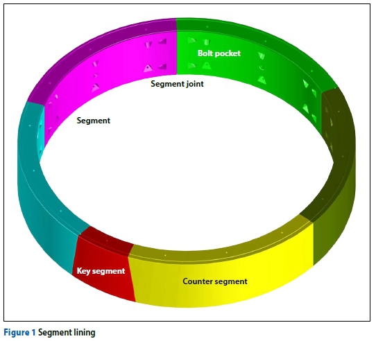
The process of subway construction is undergoing rapid developments in China. Shield-driven tunnels are widely used in soft ground because of their flexibility, cost-effectiveness, and minimal impact on ground traffic and surface structures. Segmental precast concrete linings (see Figure 1) connected by steel bolts are commonly used in shield-driven tunnels. These are one of the single most important elements in the total cost of tunnelling, representing 15-40% of the total cost (Iftimie 1994).
Segment joint opening is a common problem in shield tunnel operations, and is a major cause of water leakage. The width of the segment joint opening is an indicator of the deformation of the segmental lining. The damage caused to segment joints under large bending moments is the most common structural problem with tunnel linings.
Considerable research has focused on the mechanical behaviour of the segmental linings. Originally the linings were simplified as a uniformly rigid ring by applying a reduction factor to the flexural rigidity (nEI) of the tunnel linings (Peck et al 1972; Muir Wood 1975). Lee and Ge (2001) derived an analytical formulation of n for the flexural rigidity of segmental tunnel linings.
The existence of joints between segments is the main characteristic of prefabricated linings, because they greatly affect the bending moment, which is the dominant factor in segment damage. Thus, the influence of the segment joints on the performance of tunnel linings has attracted the attention of many researchers. Some consider the segment joints as rotational springs, and assume that the bending stiffness is constant (ITA 2000; JSCE 2000; Ding et al 2004), which means the moment-rotation (M-0) relation is linear. Subsequently, bilinear and trilinear models for the structural analysis of linings (Atsushi 2012) have been proposed to provide a better approximation.
Combining various linear models, the following uniform model can be obtained (see Figure 2):
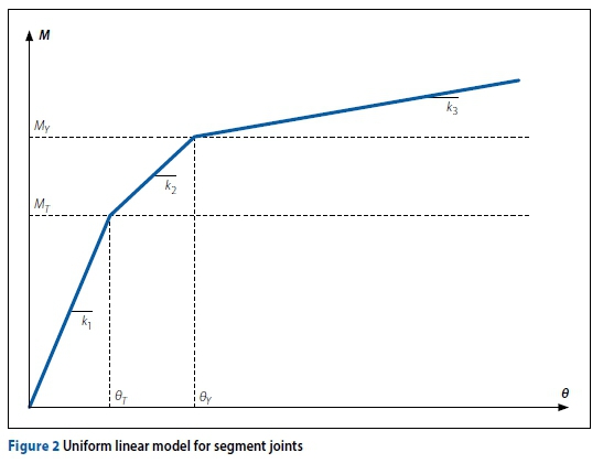
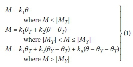
where k1is the bending stiffness before joint opening, k2is the bending stiffness after joint opening, k3 is the remnant bending stiffness after plastic deformations appear in the joint components, MTand 0Tare the bending moment and rotation angle just after joint opening, respectively, Myand 0yare the bending moment and rotation angle, respectively, just as the joint components (concrete or bolt) reach the material strength limit.
In terms of M-0 curves, full-scale joint tests suggest that the mechanical behaviour is highly nonlinear (Ding et al 2013; Li et al 2015; Blom 2000). This is because of the nonlinearity of the components and the discontinuity of the joint. The bending stiffness of the joint decreases significantly after the joint has opened.
A number of researchers have attempted to carry out M-0 calculations of segment joints. This is a critical issue in the structural analysis of the segment linings. Janssen (1983) proposed a simple theoretical model that describes the moment-rotation behaviour of segment joints in linear materials with full concrete-to-concrete surface contact. The model represents the joint as an equivalent concrete beam between two segments. This concrete element simulates the rotations in the joint and additional curvature in the two adjoining segments caused by a concentrated force introduced to the segments. The Janssen model can be written as follows:
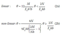
where Ecis the elasticity modulus of concrete, N is the axial force, b is the segment width, and h is the segment thickness.
Under Janssen's theory or the equivalent theory developed by Blom (2000), a unified model involving linear and nonlinear branches is established. The model can be divided into three different stages:
1. Constant bending stiffness until
where Ec is the elasticity modulus of concrete, N is the axial force, b is the segment width, and h is the segment thickness.
2. Bending stiffness is nonlinear, but the ultimate compressive strains are in the elastic branch, until e = ec, where ecis the initial plastic strain of concrete.
3. Bending stiffness is nonlinear and the ultimate compressive strains are in the plastic branch, until e = ecu, where ecuis the yield strain of concrete.
According to elasticity theory, the compressive stress distribution in the joint is nonlinear. In reality, the stresses will reach infinity at the edge of the contact area of the joint. Gladwell (1980) developed a relation for the momentrotation between two flat surfaces. The contact stresses are assumed to be concentrated on the edges of the joint. The initial stiffness of Gladwell's model is higher, and the joint stays closed for longer than in Janssen's model. Gladwell's model also contains linear and nonlinear parts:
where Ecis the elasticity modulus of concrete, N is the axial force, b is the segment width, and h is the segment thickness.
In recent years, researchers have concentrated on developing a better understanding of the joint behaviour in the hope that this will lead to improved comprehension of test results and more realistic analytical and numerical modelling. A progressive mechanical model for longitudinal joints was derived by Li et al (2015), who divided the duration of joint opening into four stages. Dong and Xie (2013) proposed an analytic three-stage model.
The objective of this paper is to investigate the opening of segment joints with growing bending moments under different levels of axial stress, and to propose an analytical model for predicting the M-0 behaviour of the joints.
MECHANICAL ANALYSIS OF CONCRETE SEGMENT JOINTS
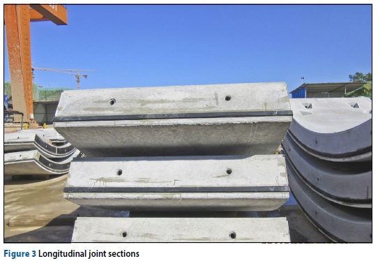
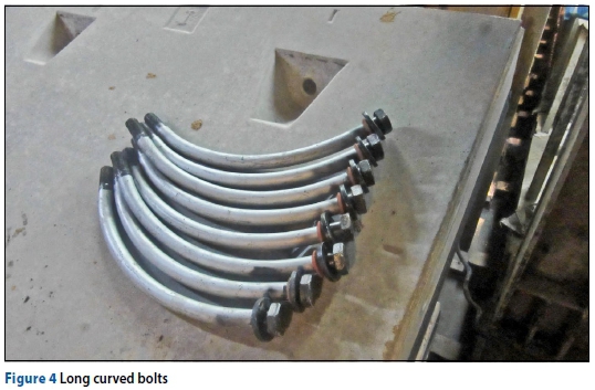
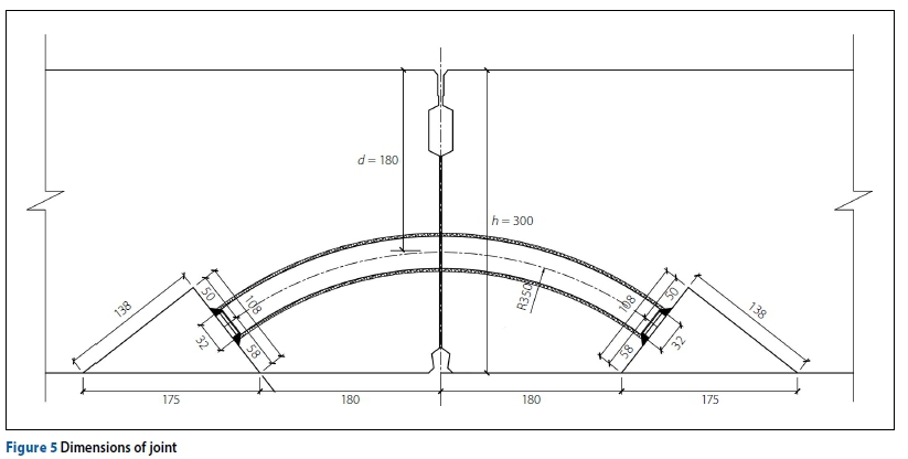
This section considers a joint in a segment lining connected by two long curved bolts (see Figures 3 and 4) similar to that used in Zhengzhou Metro Line 1 - concrete strength grade C50, anti-seepage grade P12, main reinforcement HRB335, outer diameter of lining ring 6.0 m, inner diameter 5.4 m and ring width 1.5 m. The pre-tightening force of 6.8 grade M27 bolt is 108 kN, and the distance between the centre of the bolt hole at the joint and the inner arc surface is 120 mm (see Figure 5). The segment joint can be considered as a semi-rigid connection, as in the design of numerous frame structures (Xu 2002; Yee & Melchers 1986; Dias 2014).
A concrete segment joint connected by two long curved bolts is taken as an example (Figure 5). In the case of this plane joint, adjacent segments in a ring are mostly in concrete-to-concrete surface contact without packing material. The contact area will have a reduced height in comparison with the segmental thickness (h).
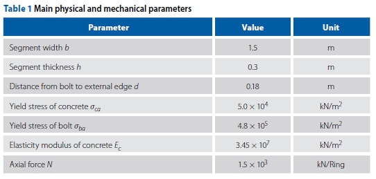
The joint dimensions and material properties are listed in Table 1.
For simplicity, several basic assumptions are needed to evaluate the model parameters. These assumptions are as follows:
1. The rotation angle and deformation of the joint are very small compared with the size of the segment.
2. The compressive and detached areas of the joint remain in the plane.
3. The depth of influence of the compression strain in the compres-sive zone is twice the height of the compressive area.
According to these assumptions, the geometric model of the segment joint can be simplified into the form illustrated in Figure 6.
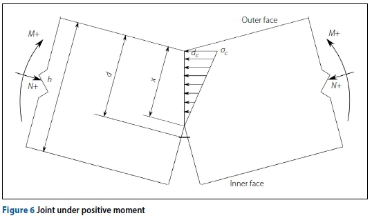
As the bolts are positioned only on the inner side of the segments, the M-0 behaviour should be investigated in two rotational directions (use Figure 6 to define + and - moments). The arc structure of the segment and the bolt position mean that the joints respond differently under positive and negative bending moments. The moment-rotation curve can therefore be divided into two separate branches. In most analytical models of segment joints, the arc structure is simplified as a straight shape, so that only the location of the bolt distinguishes the joints under positive and negative bending moments. Therefore, the parameter calculations in this model are similar when the joints are under negative bending moments. In this paper, we consider the positive moment as an example, and present a mathematical model describing the M-0 relation.
First, the physical meaning of some parameters is discussed, as this is critical to determining the M-0 behaviour of the segment joint. The initial bending stiffness of the joint, ki, describes the joint rotation at the very early stage (i.e. M = 0 = 0). The joint then starts to rotate, but no opening occurs. As the bending moment increases, the one edge of the joint becomes divided at a certain point in time. At this point, M and 0 reach values of Mdand 0d, respectively, and the bending stiffness is kd. As the bending moment M continues to increase, it reaches the plastic moment capacity of the joint, Mp, at which point the ultimate bending stiffness kpoccurs. These are the critical points of the M-0 relations, although the intervals between these critical points are also important. The parameter C is introduced to control the rate of decay of the M-0 curve.
Regarding the relationship between the bending moment and the rotation angle at the joint, the nonlinear behaviour of the joint can be analysed using experimental data. This means that the rotation stiffness depends on the rotation angle of the joint. According to the mechanical behaviour reported by previous studies (Ding et al 2013; Li et al 2015; Dong & Xie 2013; Luttikholt 2007), the M-0 curve model should satisfy the following requirements:
1. When no moment exists in a joint's section, no rotation angles will appear (M = 0 or 0 = 0), which means that the M-0 curves pass through the origin.
2. Differentiating M and substituting for 0 = 0 gives the initial bending stiffness
3. The bending stiffness k then decreases, and kiattains a value of kdat the point at which the segment joint divides. Thus, differentiating M and substituting for 0 = 0dgives kd. This requires that the M-0 curve is not only continuous, but also differentiable at 0d.
4. After the joint has opened, the bending stiffness k decreases rapidly. With the rotation angle increasing, plastic behaviour appears in one or more components of the segment joint. The moment M then increases very slowly and the bending stiffness k remains almost constant.
Besides the critical points mentioned above, there are several desirable aspects to the model. The slope of the mathematical expression of the model should correspond to the bending stiffness of the segment joint for any value of 0. Thus, the parameter C describing the decay rate of the M-0 curve is introduced.
From the experiments and numerical simulations reported by Luttikholt (2007), the M-0 curves exhibit exponential-like decay. As the rotation becomes large, the slope of the M-0 curve approaches the bending stiffness kp= 0, and the curve tends asymptotically to the moment capacity Mpof the joint. However, there are some differences before the joint opens to after the joint has opened. These two states should be considered separately. We attempt to describe the M-0 behaviour with exponential-like functions, while considering that the model should possess the properties mentioned above.
The mathematical model of the M-0 curve is assumed to be as follows:
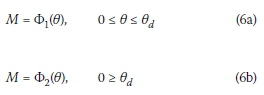
According to the requirements stated above, Model 6 should have the following properties:
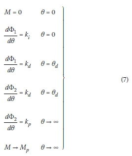
As shown in Figure 7, when the neutral axis is below the inner side of the segment joint, joint opening does not occur, and the whole section of the joint bears the compressive stress. Therefore, the bending stiffness of the joint is extremely large in this situation, and the moment mainly compensates the axial forces. The rotation angle caused by the compressive deformations is quite small. Additionally, the critical issue of the segment joint's mechanical behaviour needs only be considered after the joint has opened. In conclusion, the first equation of the mathematical model is assumed to be linear. Thus, in Equation 7, ki= kd. For the nonlinear parts, an exponential-like function is introduced to reflect the exponential decay of the M-0 curve.

According to the properties in Equation 7, the following mathematical model is derived:
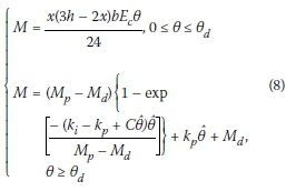
where 0 = 0 - 0d, x is the height of the compressed region (see Figure 6), Mdis the bending moment at the point at which the joint opens, Mpis the plastic moment capacity of the joint, C is a parameter describing the decay in the bending stiffness, k is the initial bending stiffness, and kpis the ultimate bending stiffness.
Model 8 satisfies the properties described at the beginning of this section. If the model parameters can be evaluated exactly, the model will qualitatively agree with experimental results in terms of the M-0 relation. In the next section, we concentrate on evaluating the parameters in Model 8.
EVALUATION OF MODEL PARAMETERS
Evaluation of kt
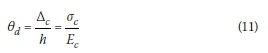
The initial bending stiffness k is considered to be a uniform bending stiffness (secant slope). Hence, k will be calculated from the unloaded state until the point of joint opening. During this interval, the bending stiffness of the joint is very large and decreases only slightly. As the neutral axis is located on the lower inside edge of the joint, i.e. the moment when the joint opens is:
it is difficult to determine the displacement Δc of the concrete on the joint's upper edge. According to Saint-Venant's principle, beyond a certain distance (lcc) from the compression area, the stress becomes uniform and uniaxial over the section profile (Collins & Mitchell 1991), i.e., σz=  and σy = 0. Ding et al (2013) investigated the value of lccby means of finite element analysis. In this study lccis assumed to be twice the height of the compression area for simplicity (Atsushi 2012). Thus, the displacement Ac of the upper outer edge has the following expression
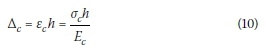
where ecand σcrepresent the strain and stress of the upper edge, respectively. The rotation angle can be calculated by
and so ki can be expressed as
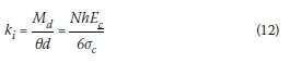
Because N =  hbσc, we have that
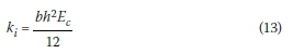
Thus, the expression for kican be rewritten as
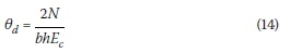
When M = Md, the rotation angle 0dis given by
Therefore, we can distinguish two stages in which the rotation angle 0 of the joint increases: 0 <  , when the joint is always closed, and 0 <,
  when the joint becomes divided along the inner edge.
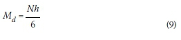
Evaluation of Mp
As the bending moment increases, the components of the joint generate plastic deformations. The joint then develops into a plastic hinge. It is the bending moment M that transforms the joint into a plastic hinge. Therefore, the moment capacity of the joint, Mp, is a critical parameter in Model 8. Mp is the maximum moment that can be transmitted by the segment joint without strain hardening, and is governed by the failure of the weakest component, such as the bolts, bolt pockets, and the concrete section of the joint. This parameter can be calculated as follows:
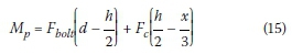
The moment capacity Mpdepends on the strength and size of the components of the joint connected by two bolts. When one or more of the following component failures appear, the joint will lose its ability to sustain further loads.
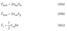
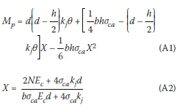
where σbais the yield stress of bolt, σcais the yield stress of concrete, Abis the cross-sectional area of the bolt, Apis the bearing area of the nut and washer on the concrete, Equation 16a indicates bolt failure (in tension), Equation 16b represents concrete squashing near the bolt pocket, and Equation 16c represents concrete squashing of the compression zone. Calculations indicate that concrete compression zone squashing will occur first, which is in accordance with the results of full-scale tests. Actually Mpcan be calculated with the help of the following equations:
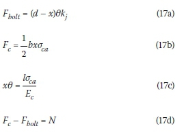
where kj is the tension spring coefficient of the segment joint. From Equation 17, the height of the compression area x can be obtained from:
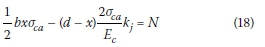
The distance x and moment capacity Mp can then be calculated. The calculation process is described in the Appendix at the end of this article.
Evaluation of kp
As strain-hardening of the joint is not considered in this study, kp= 0. According to the stress-strain relationship of the segment concrete and the M-0 curves derived from previous full-scale tests, the M-0 curve of the joint is asymptotic with respect to Mp. In this case, a plastic hinge exists, i.e. plastic deformation of the concrete compression zone occurs, and the bending stiffness of the joint tends to kp.
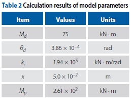
Calculation results of model parameters
Using the parameter values given at the beginning of this section, the parameters of the M-0 model can be calculated. The results are presented in Table 2.
Setting the rate of decay parameter C to values of 1 and 100, and using the parameters in Table 2, the M-0 curve can be plotted (see Figure 8). The tension spring coefficient of the segment joint, kj, is approximately equal to the tension spring coefficient of the bolts, kb. Therefore, kjcan be calculated as (Atsushi 2012):
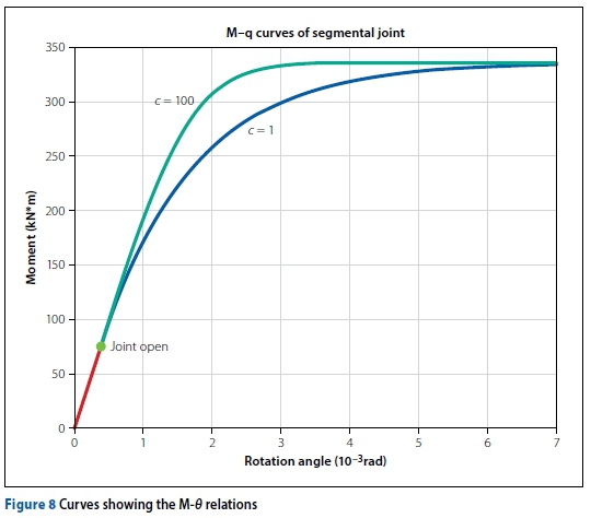
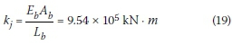
where Ebis the elasticity modulus of the bolts, Abis the useful cross-section of the bolts, and Lbis the useful length of the bolts.
MODEL VALIDATION
The proposed model of this paper is mainly dominated by the parameters of critical points Md, Mpand the parameter of decay rate C. The physical behaviour of the segment joints with an increasing bending moment, can also be reflected by these parameters. The bending moment Mddescribes the behaviour of the joint opening, and Mpdescribes the situation where the components of the joint perform plasticity. The parameter C describes the decay rate of the M-0 relation. Therefore, when using this model, the parameters Md Mp, and C should be calculated, so that th model reflects the real physical behaviour of the segment joints.
Effects on model of parameters
Evaluations indicate that the model parameters are closely related to the axial force N and the intrinsic parameters of the segment (such as the segment dimensions b, h, d and the material properties Ec, σca). Subsequently, Figure 8 was obtained, which shows the M-0 relation.
The following paragraphs discuss the main factors that influence the model parameters. According to Equations 9, 13 and 14, at the point at which the segment joint opens, the bending moment Mdand the rotation angle 0dboth increase with increasing axial force N. This is because the bending moment mainly counteracts the effects of N on the joint section. Thus, as N increases, a larger value of Mdis needed to initiate joint opening, and the increased deformation Δc will enlarge 0d. Additionally, Mdwill grow with the segment thickness h, and the rotation angle 0dwill decrease as the segmental size parameters (h, d) and the elasticity modulus Ecincrease.
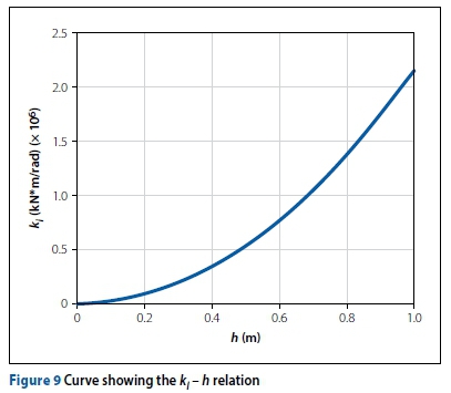
The initial bending stiffness ktwill become larger as the segmental size parameters (h, d) and elasticity modulus Ecincrease. Consequently, the straight part of the M-0 curve will extend as the axial force N increases, i.e. kiis positively related to bh2Ec. Therefore, the segment thickness h has a significant impact on the initial bending stiffness k (see Figure 9).
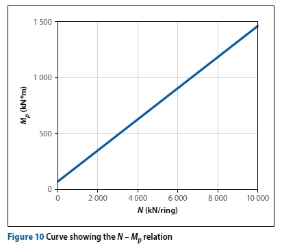
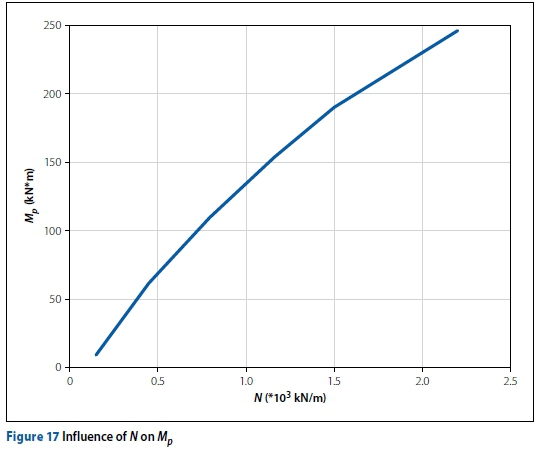
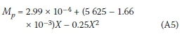
Thus, the axial force N must exceed a magnitude of 108 kN/ring for x to reach the axis of symmetry (X = 11 250; see Equation A5 in the Appendix). Until the axial force N reaches that order of magnitude, the plastic moment capacity of the joint Mpwill increase with the growth in N. Figure 10 shows that Mpand N have an approximately linear relationship, because 2Ec (the coefficient of N in Equation A4) is small compared with bσcaEc+ 4σcakj.
Comparison with other analytic models and test results
The parameter C determines the rate of decay of the M-0 curve (Maquoi & Jaspart 1987). In this study, we compare the effects of C = 1 and C = 100.
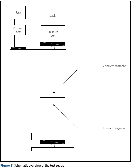
Hordijk & Gijsbers (1996) conducted experiments on segment joints without packing materials. The specimens used in the tests had a segmental thickness of 350 mm and a segmental width of 500 mm. The contact height of the joint was 158 mm. Two tunnel segments were loaded by increasing the bending moment under various normal forces. The influence of the bolts on the rotation capacity of the joints was also considered. A schematic overview of the test set-up is shown in Figure 11.
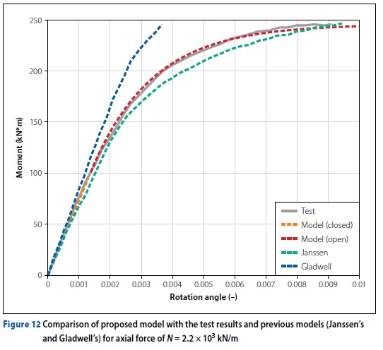
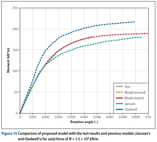
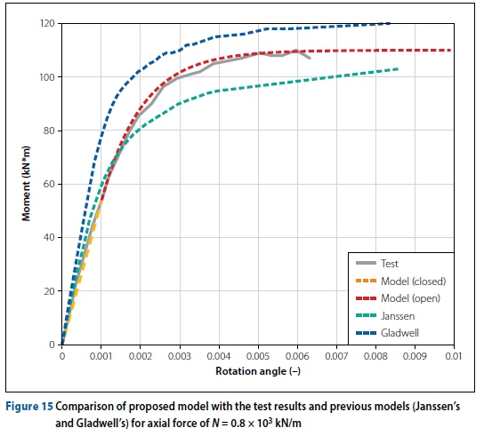
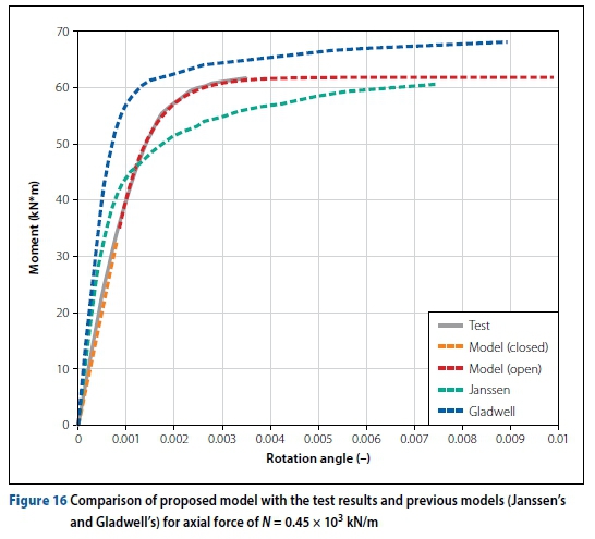
Under different axial forces, the model proposed in this paper is compared with the test results reported by Hordijk & Gijsbers (1996), Janssen's model, and Gladwell's model.
From Figures 12 - 16 it is clear that the moment-rotation curves exhibit linear and nonlinear branches. Gladwell's model always overestimates the bending moments in the joint; Janssen's model underestimates the bending moments under higher axial forces. Under lower axial forces, Janssen's model predicts larger bending moments before the joint opens. For the Janssen's and Gladwell's models, axial force N has no effect on the initial bending stiffness kt, which is not in conformity with real behaviour of segment joints. From these comparisons, it appears that our model predicts the M-0 behaviour more accurately than Janssen's and Gladwell's models.
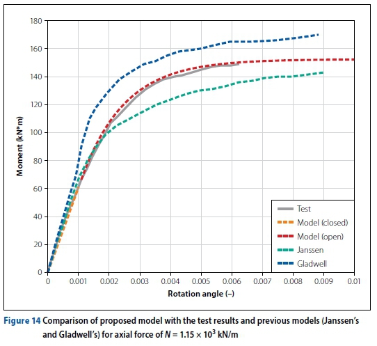
The axial force N has significant effects on the M-0 relation of the joint. The initial bending stiffness kiincreases with N, especially when N is relatively low. The plastic moment capacity of the joint Mpgrows under larger values of N.
The N - Mprelation is almost linear (see Figure 17), which is in accordance with the proposed model.
CONCLUSIONS
Bolted connections in segmental linings were regarded as semi-rigid connections in establishing a physically based mathematical model expressed by the joint dimensions and material properties. This model allows the M-0 behaviour of segment joints to be predicted.
The model parameters were evaluated, and M-0 curves for the joint were presented. The calculation process allowed us to identify the key factors that influence the model parameters. The segment thickness h has a significant impact on the initial bending stiffness ki. As h increases, the initial bending stiffness k also increases. The plastic moment capacity of the joint increases Mp approximately linearly with increases in N.
The critical mechanical behaviour of the model was revealed by the physically based parameters. With regard to critical points of the M-0 curve, the parameters Mp and Mdaccurately reflect the mechanical behaviour of the joints. With the help of a decay parameter C, the proposed model was shown to be consistent with experimental test data.
ACKNOWLEDGEMENTS
This work is supported by the National Natural Science Foundation of China (Grant Number 51278467), the National Natural Science Foundation of China (Grant Numbers 2015M582204 and 2016T90681), the Program for Science and Technology Innovation Talents at the University of Henan Province (Grant Number 14HASTIT050), and the Special Scientific Research Foundation for Young Teachers of Zhengzhou University (Grant Number 1421323078).
REFERENCES
Atsushi, K 2012. The segment design of shield tunnelling. Beijing: China Architecture and Building Press (Chinese Edition). [ Links ]
Blom, C 2000. Design philosophy of concrete linings for tunnels in soft soils. PhD thesis. Delft, Netherlands: Technical University of Delft. [ Links ]
Collins, M & Mitchell, D 1991. Prestressed Concrete Structures. Upper Saddle River, NJ: Prentice Hall. [ Links ]
Dias, D 2014. A new numerical approach to the hyperstatic reaction method for segmental tunnel linings. International Journal for Numerical and Analytical Methods in Geomechanics, 38:1617-1632. [ Links ]
Ding, W, Peng, Y, Yan, Z et al 2013. Full-scale testing and modeling of the mechanical behavior of shield TBM tunnel joints. Structural and Mechanical Engineering, 3: 337-354. [ Links ]
Ding, W, Yue, Z, Tham, L, Zhu, H, Lee, C, & Hashimoto, T 2004. Analysis of shield tunnel. International Journal for Numerical and Analytical Methods in Geomechanics, 28: 57-91. [ Links ]
Dong, X & Xie F 2013. Analytical solution of segment joint model for segmented tunnel lining. Chinese Journal of Geotechnical Engineering, 35: 1870-1975. [ Links ]
Gladwell, G M L 1980. Contact problems in the classical theory of elasticity. Alphen aan den Rijn, Netherlands: Springer Science & Business Media, p 5. [ Links ]
Hordijk, D & Gijsbers, F 1996. Laboratoriumproeven tunnelsegmenten [Laboratory experiments with tunnel lining segments]. CUR/COB. Rotterdam, Netherlands: Projectbureau boortunnels. [ Links ]
Iftimie, T 1994. Prefabricated lining, conceptional analysis and comparative studies for optimal solution. Proceedings, ITA International Congress on Tunnelling and Ground Conditions, Cairo, Egypt, pp 136A-137A. [ Links ]
ITA (International Tunnelling Association) 2000. Guidelines for the design of shield tunnel lining. Tunnelling and Underground Space Technology, 15: 303-331. [ Links ]
Janssen, P 1983. Tragverhalten von tunnelausbauten mit gelenktubbings (in German). PhD thesis, Braunschweig, Germany: Technischen Universitat Carolo-Wilhelmina. [ Links ]
JSCE (Japanese Society of Civil Engineers) 2000. The design and construction of underground structures (in Japanese). Tokyo, Japan: JSCE. [ Links ]
Lee, K & Ge, X 2001. The equivalence of a jointed shield-driven tunnel lining to a continuous ring structure. Canadian Geotechnical Journal, 38: 461-483. [ Links ]
Li, X, Yan, Z, Wang, Z & Zhu, H 2015. Experimental and analytical study on longitudinal joint opening of concrete segmental lining. Tunnelling and Underground Space Technology, 46: 52-63. [ Links ]
Luttikholt, A 2007. Ultimate limit state analysis of a segmented tunnel lining. Master's thesis, Delft, Netherlands: Technical University of Delft. [ Links ]
Maquoi, R & Jaspart, J 1987. Discussion: Moment rotation curves for bolted connections. Journal of Structural Engineering, 113: 2324-2327. [ Links ]
Muir Wood, A 1975. The circular tunnel in elastic ground. Geotechnique, 25: 115-127. [ Links ]
Peck, R, Hendron, A & Mohraz, B 1972. State of the art of soft round tunneling. Proceedings, 1st Rapid Excavation and Tunneling Conference, Chicago, IL, Vol 1, pp 259-286. [ Links ]
Xu, L 2002. Design and optimization of semi-rigid framed structures. Chapter 7, in Burns, S A. Recent Advances in Optimal Structural Design, Reston, VA: American Society of Civil Engineers. [ Links ]
Yee, Y & Melchers, R 1986. Moment-rotation curves for bolted connections. Journal of Structural Engineering, 112: 615-635. [ Links ]
 Correspondence:
PANPAN ZHAI
PhD Candidate, School of Water Science and Engineering. Zhengzhou University
WenhuaRoad 97, Zhengzhou, China
T: +86 188 3819 4945; E: panpanzhai2014@163.com
PROF PING XU
School of Water Science and Engineering, Zhengzhou University
WenhuaRoad 97, Zhengzhou, China
T: +86 137 3318 9057; E: pingxu127@163.com

PANPAN ZHAI received his MSc in Applied Mathematics in 2014 from Wenzhou University. Following a number of years as a doctoral candidate, he changed his focus to civil engineering. This paper is based on research conducted for his PhD degree.

PROF PING XU holds a PhD from the Zhejiang University. He is currently a professor in Civil Engineering at the Zhengzhou University.
APPENDIX
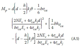
From Equations 15, 17a, 17b and 18 we obtain:
Substituting Equation A1 into A2 yields:
Here 0 = , so:
, so:
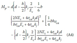
Then:

