


Services on Demand
Article
 English (pdf)
 Article in xml format
 Article references
Indicators

Related links
-
 Cited by Google
 -
 Similars in Google
Share

 Permalink
Journal of the South African Institution of Civil Engineering
On-line version ISSN 2309-8775
Print version ISSN 1021-2019
J. S. Afr. Inst. Civ. Eng. vol.61 n.4 Midrand Dec. 2019
http://dx.doi.org/10.17159/2309-8775/2019/v61n4a3
TECHNICAL PAPER
Comparing the factors of safety from finite element and limit equilibrium analyses in lateral support design
J-T Potgieter; S W Jacobsz
ABSTRACT
Soil-nails and anchors as means of lateral support in surface excavations require stability analyses as part of design. Generally, the acceptance criterion is some arbitrary 'factor of safety' which can be routinely computed using well-established principles of limit equilibrium analyses. These methods have been tested over many years and have been shown to be adequate for design. There is an increasing trend towards the use of the finite element strength reduction methods to determine factors of safety in lateral support design. Differences are often reported between factors of safety calculated using these methods. There is also a danger that engineers might use finite element modelling without full appreciation of the impact of choices and assumptions made in using the software.
This paper compares the results of limit equilibrium and finite element calculations to assess factors of safety. Under certain conditions the factor of safety from the finite element strength reduction technique is comparable with limit equilibrium methods, provided that the same failure mechanism is evaluated. In addition, in the case of anchors, the same capacity must be specified in both analyses. In defining in-situ stress states, the friction angle and Poisson's ratio should be specified so as to not violate the yield criterion. Modelling parameters (mesh grading and boundary distances) were found to have relatively minor influences on the factor of safety for the strength reduction technique.
Keywords: finite elements, strength reduction technique, limit equilibrium, soil-nails, soil anchors, factor of safety
INTRODUCTION
Urban construction projects often involve deep vertical excavations requiring lateral support. The use of soil-nails and anchors, in combination with a shotcrete facing and/or soldier piles, are popular means of lateral support. During design, the stability of the supported excavation face requires assessment.
The design philosophy with lateral support is to prevent excessive deformation and failure, and to provide a sufficient margin of safety to adequately satisfy soil, material and loading variability (Lai Sang & Scheele 1999; BS 1995). Despite serviceability considerations often being as important as failure conditions (Simpson & Driscoll 1998), design procedures generally focus on stability calculations (i.e. failure conditions), and only limited guidelines are given for serviceability requirements (SAICE 1989; Clouterre 1991).
In order to carry out stability computations, in the past, limit equilibrium calculations were exclusively used to design lateral support systems. However, finite element modelling has become increasingly popular. Further advances have also been made with regard to three-dimensional (3D) modelling. However, 3D finite element modelling remains costly and not suitable for routine analysis of most problems. It is recognised that, even if the excavation has sufficient length to represent a plane strain problem, the failure mode would still be three-dimensional. However, in almost all cases, a two-dimensional plane strain analysis is conservative (Azzouz et al 1983; Mollahasani 2015; Duncan 1996).
The use of soil-nails has rapidly expanded since the 1980s (FHWA 2003). Despite considerable work since then, the design of soil-nail support is often still based upon simplified and conservative models. General consensus has been reached that soil-nails can be adequately modelled as tensile members under normal installation angles (Jewell & Pedley 1992; Pedley et al 1990; Bridle & Davis 1997). The pull-out resistance in many soils can be calculated as a function of the effective stress at the depth of the nails. However, Heymann et al (1992) have shown that in South African residual soils, the pull-out resistance is generally independent of depth.
Anchored lateral support systems have been implemented since the 1930s (FHWA 1999). The design of anchored lateral support systems is based on an acceptable working load according to the appropriate code of practice. Working loads are obtained by factoring the ultimate capacity of the anchor. Anchor fixed-lengths are often pressure-grouted to obtain sufficient bond resistance. Soldier piles are often incorporated in anchored systems and generally extend below the base of the excavation, improving stability by creating passive resistance which can be analysed with simple methods as proposed by Broms (1968) or Wang and Reese (1986).
Various researchers have compared limit equilibrium methods and finite element modelling (Duncan 1996; Griffiths & Lane 1999; Cheng et al 2007; Tschuchnigg et al 2015). However, most of these studies were based on evaluating the factor of safety (FoS) for slope stability problems, with few examining soil-nailed and anchored lateral support systems.
The differences in calculated factors of safety from limit equilibrium and finite element strength reduction analysis are often not well understood by practising engineers. Inappropriate use of finite element techniques can contribute to catastrophic failures, e.g. the 2004 Nicoll Highway Collapse (COI 2005). Potts (2003) also cautions users regarding the complexities of finite element computations.
This study explores differences in factors of safety from simple, well-established limit equilibrium methods to finite element strength reduction methods for soil-nails and anchors. Despite many advanced numerical soil models becoming available, the Mohr-Coulomb model still remains the most widely used model in geotechnical engineering practice and is the focus of this study (ICE 2012). If the same soil model is used and the same reinforcement is used, why should the FoS, i.e. the parameter governing the stability interpretation, be different?
Definition of Factor of Safety (FoS)
The stability of an excavated face can be expressed in terms of the ratio between activating and resisting forces (or moments). The design should provide for a certain margin of safety against instability. For this purpose, a factor of safety has to be defined. Various definitions of the factor of safety exist.
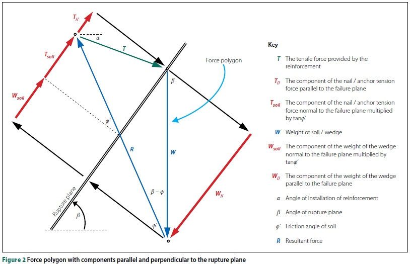
Figure 1 shows the forces acting on a single wedge failure mechanism behind an excavation face supported by a soil-nail/anchored system. Both the activating force (self-weight of the wedge, W) and the resisting force (the tension from the reinforcement, T, and friction along the failure plane) have components parallel and perpendicular to the rupture plane. Equilibrium of forces parallel to the rupture plane is considered in stability calculations. Orthogonal components of the self-weight and reinforcement tension cause friction resistance along the rupture plane, opposing sliding. Figure 2 shows the closed force polygon with four principal force components parallel to the slope requiring consideration:
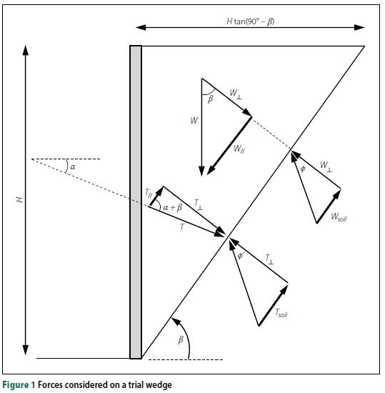
1. Tll The parallel component of the nail/anchor tension force
2. TsoilThe normal component of the nail tension multiplied by tanф'
3. WllThe parallel component of the weight of the wedge
4. WsoilThe normal component of the weight of the wedge multiplied by tanф'
In addition to these components, a surcharge could be included on the surface of the wedge. A cohesive strength component could also exist, resisting sliding on the rupture plane. Both are omitted for the sake of simplicity.
The FoS can be defined as the ratio of the forces opposing sliding failure along
the rupture plane against the forces driving failure. The definition of FoS in Equation 1 is used in literature such as Sheahan and Ho (2003), FHWA (2003), and Babu and Singh (2011).
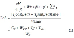
All symbols are defined in Figure 1.
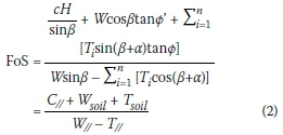
An alternative definition of the FoS in Equation 2 is used in BS (1989) and SAICE (1989). Here the parallel component of the tension reinforcement is considered as a negative driving force.
This rearrangement results in the cohesive and frictional terms appearing in the numerator. The FoS can be seen as the number by which c' and tanф' have to be divided for the system to be in equilibrium. In this formulation, the FoS is synonymous with the Strength Reduction Factor (SRF) used in calculating the FoS using finite element analyses.
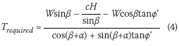
Juran and Elias (1987) advocated placing the FoS on the reinforcement capacity. This definition, shown in Equation 3, is found in codes from the early work of Stocker et al (1979), and Gässler and Gudehus (1981) (e.g. SAICE 1989).
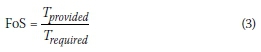
Trequiredis the capacity required on a potential slip surface to maintain equilibrium. Equations 1 or 2 can be rearranged by substituting Tiwith Trequired:
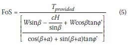
Substituting Equation 4 in Equation 3 gives:
Rearrangement gives:
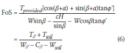
All of the above definitions are valid and appear in different codes of practice. Different definitions exist due to various authors attributing the variability to be considered in a design to different components. At failure, i.e. FoS = 1.0, Equations 1, 2 and 6 are identical. When a partial factor method is used, attributing variability to each component, a unique overall FoS would be specified.
The formulation of FoS in Equation 2 was used in this paper to compare different methods of analysis.
Analysis methods considered
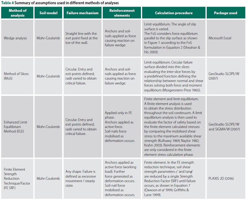
Limit equilibrium methods are routinely used to analyse slope stability problems (Tschuchnigg et al 2015). Finite element methods also provide possibilities to assess the stability of supported excavation faces. Four methods of analysis are discussed below-
Wedge Analysis
The first, and also the simplest, method is the limit equilibrium Coulomb wedge analysis. The failure surface is assumed to be a straight line with the exit point fixed at the toe of the wall. The angle of slip surface is then varied to obtain the minimum FoS. The soil shear strength is based on the Mohr-Coulomb failure criterion. The FoS considers force equilibrium parallel to the slip surface as shown in Figure 1 according to the FoS formulation in Equation 2. The wedge analysis was implemented in a spreadsheet based on the Sheahan and Ho (2003) trial wedge method.
Method of Slices
The second limit equilibrium method investigated is the Method of Slices (MoS). The Morgenstern-Price (1965) method was used in this study, solving both force and moment equilibrium, and evaluating the inter-slice forces by a predefined function defining the relationship between normal and shear forces. Analyses were carried out using SLOPE/W (part of the GeoStudio suite).
Enhanced Limit Equilibrium Method
Krahn (2003) suggested using a combined finite element and limit equilibrium approach to calculate the FoS. A finite element analysis is used to obtain the stress distribution throughout the soil continuum. A limit equilibrium analysis is then used to evaluate the FoS based on the finite element calculated stresses by comparing the mobilised shear stress to the maximum available shear strength. This is known as the Enhanced Limit Equilibrium (ELE) Method (Kulhawy 1969; Naylor 1982). The rationale behind the ELE Method is to obtain a more realistic stress distribution along a slip surface than that obtained from the conventional MoS. An important aspect to note is that reinforcement elements are only considered in the finite element stress calculation phase. The GeoStudio suite was used to carry out analyses with the ELE Method.
Finite Element Strength
Reduction Technique
Finally, the finite element (FE) strength reduction technique was evaluated. Since Griffiths and Lane (1999) popularised the idea of using a strength reduction factor in finite element displacement analyses, an increase in the use thereof to calculate the FoS has been observed in industry (Tschuchnigg et al 2015). Cheng et al (2007) found that factors of safety from limit equilibrium methods compare well with finite element strength reduction methods for slope stability problems.
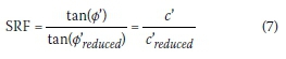
In the FE strength reduction technique, soil shear strength parameters c' and tanф' are reduced by a single Strength Reduction Factor (SRF) until failure occurs as shown in Equation 7. Failure is defined as either excessive deformation or an inability of the software to reach a converged solution. In this study, the software package PLAXIS 2D (2016) was used to calculate the SRF.
The finite element method has the distinct advantage of computing deformation; however, advanced models such as the Hardening Model (Addenbrooke et al 1997) have to be applied to consider realistic deformations (Obrzud 2010). Although the authors recognise that deformations are no less important to a good design, the purpose of this study is to consider the stability parameter commonly used: Factor of Safety.
Material parameters
The soil parameters used for this study are summarised in Table 1. The material was assumed to be uniform, homogenous and isotropic. The parameters were selected to be representative of those typically used to model excavations in residual granite in Johannesburg, South Africa.
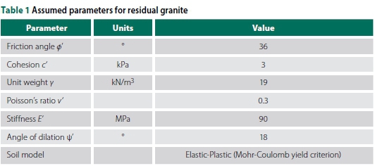
An elastic-plastic soil model with the Mohr-Coulomb yield criterion was used, as this is still the most widely used model in general geotechnical practice (ICE 2012). The stiffness parameters (E' and v') were estimated for a dense material based on Bowles (1996).
ANALYSES CONDUCTED
Soil-nail supported excavation
An 8.5 m deep soil-nailed excavation was analysed as shown in Figure 3. The major factors to be determined during design are the soil-nail bar diameter and length. The bar diameter governs the yield capacity, while the length determines the pull-out resistance.
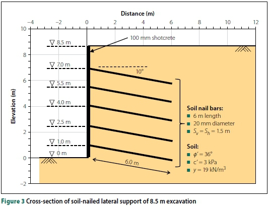
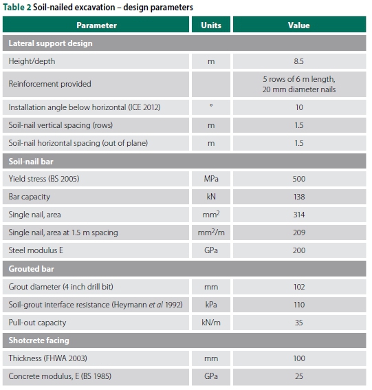
The pull-out resistance is a function of the allowable soil-grout interface shear stress, the drilling diameter and the length of soil-nail behind the most critical slip surface. The allowable soil-grout interface stress was taken as 110 kPa, a conservative estimate appropriate for residual granites in Johannesburg. Considering a drilling diameter of 102 mm, this provides a unit pull-out resistance of 35 kN/m. The soil-nail bar yield stress of 500 MPa was assumed from BS (2005). A 100 mm thick shotcrete face was assumed to adequately support the excavation face between soil-nails (FHWA 2003).
The required bar diameter and soil-nail length were determined from a limit equilibrium wedge analysis with a minimum FoS of 1.5. Five rows of 6 m long nails of 20 mm diameter were used to stabilise the excavation, providing a minimum FoS of 1.58. The critical failure plane extended at 41° above the horizontal from the excavation toe. The design and reinforcement parameters are summarised in Table 2.
Modelling
Soil-nails are generally modelled as pure tensile members (Jewell & Pedley 1992; ICE 2012). The capacity of a soil-nail is governed by the pull-out resistance, with the bar yield strength as upper limit. In the Wedge and MoS analyses, the magnitude of the nail pull-out resistance, given a certain rupture plane, is determined from the length of the soil-nail behind the failure surface multiplied by the unit pull-out resistance. The MoS assumes that this force can be applied to the base of the slice through which the soil-nail passes. In the case of the wedge analysis, the nail force is considered, as explained under the factor of safety definition above.
For the Enhanced Limit Equilibrium Method analysed using the Geostudio suite, soil-nails were specified as beam structural members. The ELE Method is suitable for calculating stress states under working stress conditions. It then uses the stress state to calculate a factor of safety using the MoS. The ultimate pull-out resistance and nail-yield strength were not considered. Generally, reinforcement is modelled as an elastic material.
Fan and Luo (2008), and Shiu and Chang (2006) used PLAXIS to model soil-nailed structures using plate and interface elements. However, the interface strength is governed by the surrounding soil strength, governed by the effective stress in a drained case. Heymann et al (1992) showed that, in the stiff residual soils in Johannesburg, the pull-out resistance is generally not a function of effective stress and that unit pull-out resistances can be taken as constant. Soil-nails were therefore specified as a combination of embedded piles and plates as shown in Figure 4. Plate elements can be specified as elastoplastic materials with a maximum tensile capacity defining yielding, after which the material behaves as perfectly plastic. Embedded pile elements can be specified to have a maximum pull-out resistance. The length of the embedded pile section was specified so that the total pull-out resistance was equal to the plate-yield strength. A slip surface passing in front of the embedded pile element (e.g. Slip A, Figure 4) will therefore trigger a yielding failure, while a failure passing through the embedded pile section (e.g. Slip C, Figure 4) will result in a pull-out failure.

The shotcrete facing was modelled using beam and plate elements in Geostudio and PLAXIS respectively. The shotcrete facing was assumed to deform elastically.
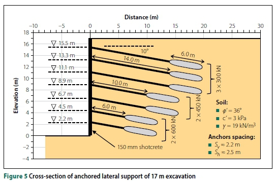
Anchored excavation
In general, anchors have higher tensile strength and pull-out resistance than soil-nails. Prestressed anchors are also more effective at controlling movements, due to being an active system. Figure 5 presents a cross-section of the anchored excavation showing the anchor layout and other relevant parameters.
When designing anchors, the major outputs are the required anchor capacities and layout. The layout is specified in terms of anchor spacing (vertical and horizontal), and free- and fixed-lengths. The load in the anchors after stressing is referred to as the anchor's working-load. Anchors typically have additional capacity in excess of the working load that is used to provide for proof testing, lock-off losses, creep, and safety factors on the material strength and pull-out resistance.
Pressure grouting significantly increases the load-carrying capacity of the fixed-length (PTI 1996; FHWA 1999). The pull-out resistance of the anchor fixed-length is not easily predicted and, for this reason, codes allow for the fixed-length to be proof-tested at a load in excess of the working load. In order to compute an FoS for a failure surface passing through the fixed-length, the following assumptions were made:
■ The pull-out resistance varies linearly along the 6 m grouted length.
■ The total pull-out resistance was set equal to the yield capacity of the anchor (proof-load testing will be approximately 90% of the yield capacity).
■ For a failure surface passing through the anchors, the pull-out capacity can be determined using the portion of the fixed-length behind the failure plane.
Following ASTM (1987), seven-wire, 15.2 mm diameter steel strands were assumed. An acceptable working load of 150 kN per strand was used (SAICE 1989; Parry-Davies 2010) together with an assumed shotcrete facing of 150 mm thick.
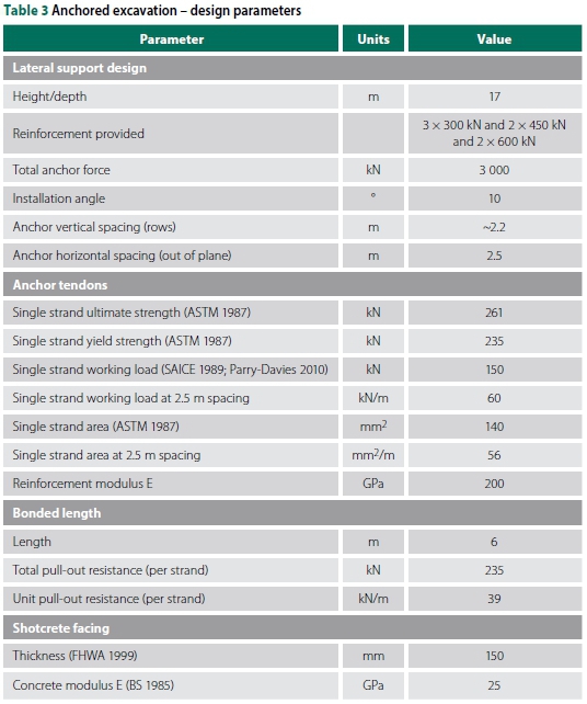
The required tensile force was determined using a limit equilibrium wedge analysis with a target FoS of 1.5. Anchor working loads were provided as shown in Figure 5, resulting in a minimum FoS = 1.51. Adequate free-lengths were provided to ensure that the critical FoS would pass through the free-lengths and not around the back of the anchors. The critical failure surface was determined at an angle of 62° from the horizontal, extending from the toe. The design and reinforcement properties are summarised in Table 3.
Modelling
Anchors provide a constant force extending from the anchor head at the shotcrete facing to the fixed-length via tendons in a sheath. This force was specified as a working load according to Figure 5. In the Wedge and MoS analyses, the working load in the anchors was specified as a force applied to the failure wedge. The MoS assumes that the force is applied to the base of the slice through which the anchor passes.
For the Enhanced Limit Equilibrium analysis, using the Geostudio suite, anchors were specified using a combination of plates for the fixed-length and bars for the free-lengths. Bar elements span across soil elements, transferring the anchor working load from the shotcrete facing to the fixed-length. The working load was specified as a pre-tensioned force in the bar elements. Structural elements in Geostudio are modelled elastically.
For the finite element strength reduction technique, a combination of node-to-node anchors and embedded piles was used to model the free- and fixed-lengths respectively using PLAXIS. The node-to-node anchors were taken as elastoplastic materials with a stiffness and yield capacity as specified in Table 4. Staged construction was modelled, with the anchor working load applied when the anchor was installed.
RESULTS AND DISCUSSION
Sensitivity to various parameters
A parametric study was carried out to evaluate the influence of variations in the input parameters on the factor of safety.
Model boundaries and meshing
Finite element analyses were carried out to assess factors of safety using the ELE and FSRF methods. The extent of the model, mesh resolution and grading and the element type must be specified.
A linear elastic-perfectly plastic Mohr Coulomb model was used for both ELE and SRF Methods.
Figure 6 shows the variation in FoS with the number of elements in the finite element model of the soil-nailed wall (in the case of anchors, the findings were similar). For the ELE Method, the FoS is sensitive to the number of elements. A large number of elements is required when selecting a uniform mesh size. Refining the mesh around structural elements (graded meshing) significantly decreases the total number of elements needed. The ELE Method FoS was found to also be sensitive to the lateral model extent.
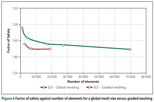
Using PLAXIS, the FE (SRF) Method was found to be less sensitive to the model size and the number of elements. This is most likely attributable to the use of higher order 15-noded triangular elements compared to the first order elements used for the ELE analyses.
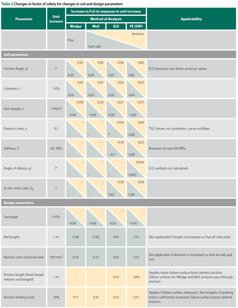
Material and reinforcement parameters
Soil properties and typical design parameters were varied to assess the influence on the FoS. Table 5 shows the sensitivity of the FoS to several input parameters for both the 8.5 m soil-nailed and 17 m anchored excavations. A near-linear correlation was generally found between the FoS and tabulated parameters.
The Wedge and MoS analyses show good correlation with the FE (SRF) Method across a range of values. However, trends from the ELE Method differed from the other methods. Unlike the other three methods, the ELE Method showed significant changes in FoS when changing Young's modulus, Poisson's ratio and the in-situ stress state. Furthermore, changing the soil-nail length and bar diameter did not significantly impact on the FoS. The reason for the differences is that the ELE Method evaluates the FoS at a working state and not at failure. Since soil-nails are passive systems, the capacity of the soil-nails is not considered when analysing the working state. The parameters mentioned above affect the stresses at working state, and hence influence the FoS. The other methods evaluate the FoS at failure state. The ELE Method is therefore not recommended for calculating the FoS when reinforcement elements are involved.
In-situ stress violations
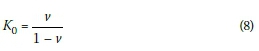
When carrying out finite element computations, the initial in-situ stress state must be specified. Several options exist, depending on the problem under consideration and the software used. Commonly, a gravity turn-on procedure is used where the weight of the soil is 'switched on'. Vertical stresses are calculated from self-weight. For an elastic plane-strain problem with a horizontal soil surface, the horizontal stresses are a function of Poisson's ratio, with the coefficient of lateral earth pressure at-rest defined as:
Another common way to specify the in-situ horizontal stresses is by using Jaky's (1944) empirical solution:
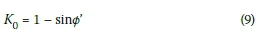
SIGMA/W, by default, uses Equation 8 to define the in-situ stress state, while PLAXIS uses Equation 9. Most software also allows the user to manually specify the in-situ stress state.
Using the Mohr-Coulomb model, the yield criterion is a function of the soil shear strength parameters, c' and φ'. It is therefore possible to specify the in-situ stress state using Equation 8 so that K is less than the active pressure coefficient (Ka). This violates the yield criterion. Poisson's ratio must therefore not be defined indiscriminately without considering this aspect.
Failure mechanisms
An advantage of the FE (SRF) Method is the ability to determine a failure mechanism without making any a priori assumptions about its shape or position. The traditional trial wedge method typically assumes a straight line with the exit point specified at the toe of the wall, while the MoS generally assumes a circular failure surface.
The FoS calculated using the trial wedge method and method of slices was found to agree well. For soil-nails, the FE (SRF) Method generally provided a somewhat lower FoS compared to the limit equilibrium analyses across a range of variables considered. Conversely, for anchored walls, the FoS provided by the FE (SRF) Method was slightly higher than for the limit equilibrium methods. However, the trends were found to be similar, i.e. an increase in friction angle results in the same increase for the limit equilibrium and the FE (SRF) Methods. The difference in failure mechanisms (i.e. the shape of the failure surface) is the primary cause for the differences in FoS between limit equilibrium and FE (SRF) Methods.
Soil-nailed excavation
Figure 7 shows the incremental shear strain distribution at failure for the soil-nailed excavation. Clear bands indicate the mechanism calculated using the FE (SRF) Method. At the exit end of the failure surface at the toe of the wall, a small passive wedge is seen extending approximately 1 m below the toe of the wall. On the entry end, the failure surface steepens behind the end of the soil-nailed block. Neither the planar Wedge Method nor the MoS or the ELE Method capture this mechanism adequately. However, a limit equilibrium multiple wedge analysis comprising a double wedge behind the excavation face with a passive resisting wedge at the toe can be used to approximate the FE (SRF) mechanism described.
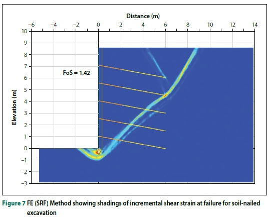
Figure 8 shows a single, double and a compound mechanism with a passive wedge below the toe. A marked decrease in the FoS from 1.58 to 1.37 is observed for a failure extending beneath the toe of the excavation.
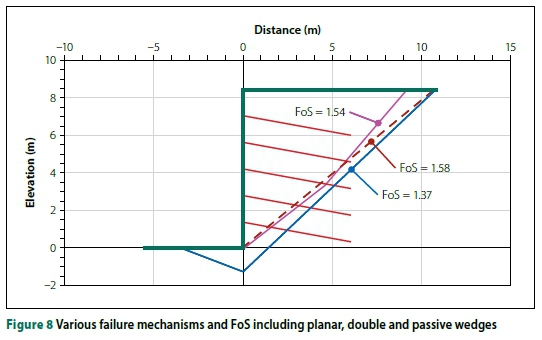
Figure 9 illustrates Rankine active and passive pressures, with the net positive pressure highlighted. For a shallow depth below the toe, the positive active pressure exceeds the resisting passive pressure, explaining the reduced factor of safety associated with mechanisms extending below the excavation toe. When using a multiple wedge mechanism, the FoS calculated for a soil-nailed excavation agrees well with that calculated from the finite element strength reduction technique.
Anchored excavation
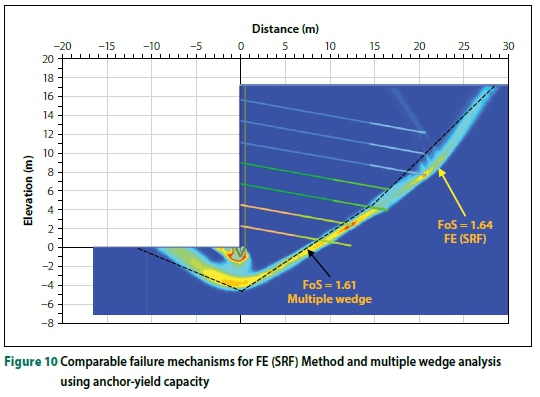
As for soil-nails, the differences in FoS observed for anchored excavations can be partially attributed to difference in failure mechanisms. An additional difference between the limit equilibrium methods and the FE (SRF) Method is associated with the capacity of the anchors. In the FE (SRF) Method, despite the working load being specified, the soil shear strength is reduced to such an extent that the anchor-yield capacity is eventually mobilised. Since the yield capacity is in excess of the working load, the working load becomes irrelevant when the SRF is calculated to failure. The limit equilibrium FoS calculation uses the working load in the anchors, while the yield capacity is generally used in FE (SRF) calculations.
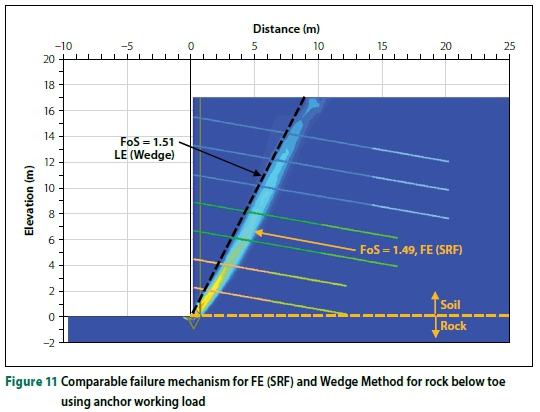
Figure 10 shows good agreement between the FoS when a multiple wedge failure resembling the FE (SRF) mechanism is compared. In this scenario, the anchor-yield capacity was specified in both methods of analysis. Figure 11 demonstrates the same point - the working load was used in both methods, and material below the toe was specified as rock, forcing the failure through the toe of the excavation. Close agreement is seen between the FoS from both methods.
Strength Reduction Technique -parameter insensitivity
The major factor driving instability in a laterally supported excavation is the weight of the retained soil. Stability of the anchored excavation, with an adequate FoS, is ensured by providing reinforcement. Since an unreinforced system cannot achieve static equilibrium - i.e. there is a deficit in force/ moment resistance - an increase in unit weight should theoretically further increase this deficit and hence decrease the FoS.
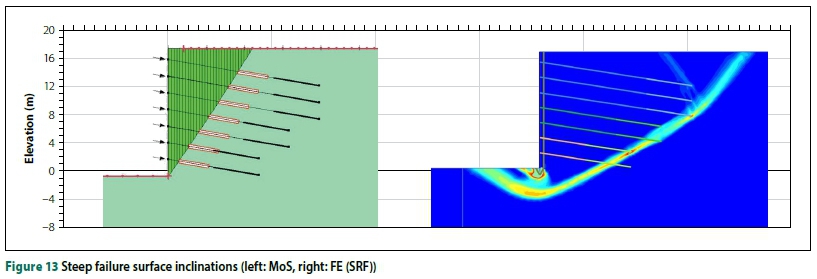
Figure 12 shows the influence of unit weight on the FoS calculated using the four methods considered. The finite element methods seem to be insensitive to a change in unit weight. The reason becomes apparent when examining the associated failure mechanisms illustrated in Figure 13. For steeply inclined failure wedges, the driving force (component of the soil weight parallel to the failure plane) exceeded the resistive force (frictional resistance along the failure plane). For flat failure surfaces, the driving force could be matched by mobilising more frictional resistance.
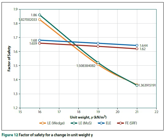
As explained above, the FE (SRF) Method uses the yield capacity of the anchors instead of the working load used by limit equilibrium methods. This increased anchor strength results in the critical rupture surface extending behind the fixed-lengths instead of through the free-lengths of the anchors. The shape and position of the failure mechanism clearly affect the sensitivity of the FoS to certain soil and design parameters.
Further parameter insensitivity in terms of a strength reduction analysis is illustrated below.
Figure 14 represents hypothetical loads mobilised against the back of a retained excavation face as a function of face movement. The nett driving force from the soil and the resisting force of the soil-nails are plotted on the vertical axis. The nett driving force from the soil is expressed in terms of the mobilised horizontal earth pressure coefficient.
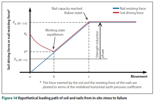
Suppose the soil-nails were 'wished into place' and that the initial in-situ horizontal soil stresses are defined by K0. Initially (at point a), no force is mobilised in the nails as no movement of the excavation face had occurred. As the excavation face is allowed to move, tensile load will mobilise within the nails and, at the same time, the horizontal earth pressure coefficient within the soil will begin to reduce from K towards Ka. As the face is allowed to move further, an equilibrium point will be reached where the driving force from the soil and the restraining force from the nails will match (point b). The point of equilibrium, and hence the amount of movement to reach this state, depends on the stiffnesses of the soil and nails, as well as the initial in-situ stress.
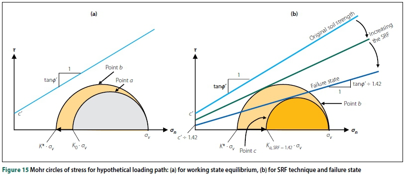
The evolution of the stress state on a hypothetical rupture plane associated with the above scenario is illustrated using the Mohr circle diagram in Figure 15(a). The Mohr circles representing the initial stress state (point a) and the stress state at equilibrium (point b) fall below the failure envelope which is represented in Figure 14 by Ka, SRF = 1. The soil is not yet in a state of failure. Now, at point b, strength reduction commences and the SRF is gradually increased, reducing the soil shear strength as shown in Figure 15(b). Initially, as the shear strength reduces, the stress state in the soil is unaffected until the reducing failure envelope touches the Mohr circle defining the stress state at equilibrium (point b). From this point onwards, the horizontal stress (defined by Ka) increases with the increasing SRF. This is accompanied by increasing yielding on the rupture plane.
As the horizontal stress exerted by the soil increases, the force within the nails will also increase to maintain equilibrium. Equilibrium will be maintained up to the point where the soil shear strength has been reduced to such an extent that the nails reach their capacity (pull-out or nail yield, point c in Figure 14). Beyond this point, equilibrium can no longer be maintained and failure occurs.
Figure 14 shows that the magnitude of the SRF at failure depends only on the reduction in soil shear strength required to transition between the initial active state (SRF = 1.0 in Figure 14) and a state that will cause the nails to fail (SRF = 1.42 in Figure 14). Note that the magnitude of the SRF at failure does not depend on the location of the point of equilibrium (point b). Using the FE (SRF) Method, the FoS is also independent of the initial stress ratio, K0, the stiffness parameters, E and v', or modelling of the construction sequence (affecting the stress distribution behind the excavation face). However, these variables are likely to alter the stress state at working conditions (point b).
CONCLUSIONS
Practising engineers often come across significant differences in FoS calculated by different methods when designing lateral support for applications such as deep excavations. A comparison of limit equilibrium and finite element methods for stability analysis of soil-nailed and anchored excavations was presented with specific relation to the factor of safety (FoS) outcome.
A parametric study shows that the influence of changes in variables on the FoS is significantly influenced by the shape of the failure mechanism. Using the soil unit weight as an example: for steeply inclined failure wedges, an increase in unit weight decreases the FoS; however, for flat failure surfaces, the opposite is true.
At shallow depth immediately below the toe, the positive active pressure exceeds the resisting passive pressure, explaining the reduced factor of safety associated with mechanisms extending below the excavation toe.
It was found that FoS from the traditional single trial wedge method and the method of slices compare well over the range of analyses conducted. Factors of safety from the enhanced limit equilibrium method do not compare well with those from other methods, because it evaluates FoS at working state. The ultimate capacities of the reinforcement and the soil are therefore not necessarily considered.
The finite element strength reduction method produces an optimised failure mechanism and no a priori assumptions are required regarding the failure surface. The finite element strength reduction method FoS is not influenced by stiffness variables, in-situ stresses or staged construction modelling (which affect the stress state behind the retained excavation face). The FoS is only influenced by the yield criteria of the various materials and the initial (unreduced) material properties. Factors of safety from the finite element strength reduction method and limit equilibrium methods are comparable under the following conditions:
1. Consistent failure mechanisms have to be applied (e.g. using a double-wedge failure mechanism).
2. The same ultimate reinforcement capacities, at failure, have to be considered.
3. Soil strengths are considered at ultimate state, not working state stresses.
4. The same formulation of factor of safety has to be established.
Much experience has been gained in recent times on the assessment of the stability of soil-nailed and anchored excavations using the finite element strength reduction method. However, the increased complexity involved with finite element modelling necessitates cross checks with simpler limit equilibrium methods.
ACKNOWLEDGEMENTS
The authors would like to thank Mr Shaun Nell of Terra Strata for the funding provided to support this project, as well as Verdicon Consulting Engineers and Mr Ken Schwartz for their input on technical aspects.
REFERENCES
Addenbrooke, T, Potts, D & Puzrin, A 1997. The influence of pre-failure soil stiffness on the numerical analysis of the tunnel construction. Geotechnique, 47(3): 693-712. [ Links ]
ASTM 1987. ASTM A 416. Standard Specification for Uncoated 7-Wire Stress Relieved Steel Strand for Prestressed Concrete. ASTM: Philadelphia, PA. [ Links ]
Azzouz, A S, Baligh, M M & Ladd, C C 1983. Corrected field vane strength for embankment design. Journal of Geotechnical Engineering, 109(5): 730-734. [ Links ]
Babu, G L S & Singh, V K 2011. Reliability-based load and resistance factors for soil-nail walls. Canadian Geotechnical Journal, 48: 915-930. [ Links ]
Bowles, J E 1996. Foundation Analysis and Design, 2nd ed. New York: McGraw-Hill. [ Links ]
Bridle, R J & Davies, M C R 1997. Analysis of soil nailing using tension and shear: Experiment observations and assessment. Proceedings, ICE Geotechnical Engineering, 125(3): 155-167. [ Links ]
Broms, B B 1968. Swedish tieback system for sheet pile walls. Proceedings, 3rd Budapest Conference on Soil Mechanics and Foundation Engineering, 15-18 October 1968, pp 391-403. [ Links ]
BS (British Standard) 1985. BS 8110-2 1985. Structural Use of Concrete. Code of Practice for Special Circumstances. London: British Standards Institution. [ Links ]
BS (British Standard) 1989. BS 8081 1989. Ground Anchorages. London: British Standards Institution. [ Links ]
BS (British Standard) 1995. BS 8006 1995. Code of Practice of Strengthened/Reinforced Soils and Other Fills. London: British Standards Institution. [ Links ]
BS (British Standard) 2005. BS 4449 2005. Steel for the reinforcement of concrete. Weldable reinforcing steel. Bar, coil and decoiledproduct. Specification. London: British Standards Institution. [ Links ]
Cheng, Y M, Lansivaara, T & Wei, W B 2007. Two-dimensional slope stability analysis by limit equilibrium and strength reduction methods. Computers and Geotechnics, 34(3): 137-150. [ Links ]
Clouterre 1991. French National Research Project Clouterre [English translation, 1993]. Report FHWA-SA-93-026. Washington, DC: Federal Highways Administration. [ Links ]
COI (Committee of Inquiry) 2005. Report of the Committee of Inquiry into the Incident at the MRT Circle Line Worksite that led to the Collapse of Nicoll Highway on 20 April 2004. Magnus, R, Teh, C I & Lau, J M. (Eds), Singapore: Government Ministry of Manpower. [ Links ]
Dawson, E M, Roth, W H & Drescher, A A 1999. Slope stability analysis by strength reduction. Geotechnique, 49(6): 835-840. [ Links ]
Duncan, J M 1996. State of the art: Limit equilibrium and finite-element analysis of slopes. Journal of Geotechnical Engineering, 122: 577-596. [ Links ]
Fan, C C & Luo, J H 2008. Numerical study on the optimum layout of soil nailed slopes. Computers and Geotechnics, 35(4): 585-599. [ Links ]
FHWA 1999. Geotechnical Engineering Circular No. 4. Ground anchors and anchored systems. Report FHWA-IF-99-015. Washington, DC: Federal Highways Administration. [ Links ]
FHWA 2003. Geotechnical Engineering Circular No. 7. Soil nail walls. Report FHWA0-IF-03-017. Washington, DC: Federal Highways Administration. [ Links ]
Gässler, G & Gudehus, G 1981. Soil nailing - some aspects of a new technique. Proceedings, 10th International Conference on Soil Mechanics and Foundation Engineering, 15-19 June 1981, Stockholm, Sweden, pp 665-670. [ Links ]
GeoStudio Version 2007. Geo-Slope International, Calgary, Canada. [ Links ]
Griffiths, D V & Lane, P A 1999. Slope stability analysis by finite elements. Geotechnique, 49(3): 387-403. [ Links ]
Heymann, G, Rhode, A W Schwartz, K & Friedlaender, E 1992. Soil nail pull-out resistance in residual soils. Proceedings, International Symposium on Earth Reinforcement Practice, 11-13 November 1982, Kyushu, Japan, Vol 1: 487-492. [ Links ]
ICE (Institution of Civil Engineers 2012. Burland, J, Chapman, T, Skinner, H & Brown, M. (Eds). ICE Manual of Geotechnical Engineering, Vols 1 & 2. London: ICE Publishing. [ Links ]
Jaky, J 1944. The coefficient of earth pressure at-rest. ASCE Journal of Geotechnical Engineering Division, 111(3): 302-318. [ Links ]
Jewell, R A & Pedley, M J 1992. Analysis for soil reinforcement with bending stiffness. ASCE Journal of Geotechnical Engineering, 118(10): 1505-1528. [ Links ]
Juran, I & Elias, V 1987. Soil nailed retaining structures: Analysis of case histories. ASCE Special Geotechnical Publication No 12, ASCE: Reston, VA, pp 232-244. [ Links ]
Krahn, J 2003. The 2001 R M Hardy Lecture: The limits of limit equilibrium analyses. Canadian Geotechnical Journal, 40: 643-660. [ Links ]
Kulhawy, F H 1969. Finite element analysis of the behaviour of embankments. PhD Thesis. University of California at Berkeley. [ Links ]
Lai Sang, J & Scheele, F 1999. Experimental and numerical investigation of soil-nailed wall structures. In Wardle, G R, Blight G E & Fourie, A B (Eds), Geotechnics for Developing Africa. Rotterdam, Netherlands: Balkema, 177-182. [ Links ]
Mollahasani, A 2015. Application of submerged grouted anchors in sheet pile quay walls. PhD Thesis. University of Bologna, Italy. [ Links ]
Morgenstern, N R & Price, V E 1965. The analysis of the stability of general slip surfaces. Geotechnique, 15(1): 79-93. [ Links ]
Naylor, D J 1982. Finite elements and slope stability. In Martins, J B (Ed), Numerical Methods in Geomechanics, 2nd ed. Dordrecht, Netherlands: D. Reidel Publishing Co. [ Links ]
Obrzud, R F 2010. On the use of the hardening soil small strain model in geotechnical practice. In Zimmermann, T, Truty, A & Podles, K (Eds), Numerics in Geotechnics and Structures. Lausanne, Switzerland: Elmepress Int, pp 15-38. [ Links ]
Parry-Davies, R. 2010. A personal account of the history of ground anchors in Southern Africa including some practical guidance on the subject. Midrand: SAICE Geotechnical Divison. [ Links ]
Pedley, M J, Jewell, R A & Milligan, G E W 1990. A large-scale experimental study of soil-reinforced interaction. Ground Engineering, July/August, 44-50, and Ground Engineering, September, 46-49. [ Links ]
PLAXIS 2D (2016). Plaxisbv, Delft, Netherlands. [ Links ]
PTI (Post-Tensioning Institute) 1996. Recommendations for prestressed rock and soil anchors.PTI: Phoenix, AZ, 57. [ Links ]
Potts, D M 2003. 42nd Rankine Lecture: Numerical analysis: A virtual dream or practical reality? Geotechnique, 53(6): 535-572. [ Links ]
SAICE (South African Institution of Civil Engineering) 1989. Lateral support in surface excavations - Code of Practice. Midrand: SAICE Geotechnical Division. [ Links ]
Sheahan, T & Ho, H 2003. Simplified trial wedge method for soil nailed wall analysis. Journal of Geotechnical and Geoenvironmental Engineering. 129(2): 117-124. [ Links ]
Shiu, Y K & Chang, G W K 2006. Effects of inclination, length pattern and bending stiffness of soil nails on behaviour of nailed structures. GEO Report No 197. Hong Kong: Geotechnical Engineering Office. [ Links ]
Simpson, B & Driscoll, R 1998. Eurocode 7 - A Commentary. Watford, UK: Construction Publications Ltd. [ Links ]
Stocker, M F Korber, G W Gassler, G & Gudehus, G 1979. Soil nailing. Proceedings, International Conference on Soil Reinforcement, Paris, Vol 2, 469-474. [ Links ]
Tschuchnigg, F, Schweiger, H F, Sloan, S W, Lyamin, A V & Raissakis, I 2015. Comparison of finite-element limit analysis and strength reduction techniques. Geotechnique, 65(4): 249-257. [ Links ]
Wang, S-T & Reese, L C 1986. Study of design methods for vertical drilled shaft retaining walls. Austin, TX: Texas State Department of Highways and Public Transportation. [ Links ]
 Correspondence:
JEAN-TIMOTHY POTGIETER
Department of Civil Engineering
University of Pretoria
Pretoria 0002
South Africa
T: +27 83 308 3729
E: potgieter.jean@gmail.com
PROF SW JACOBSZ
Department of Civil Engineering University of Pretoria
Pretoria 0002
South Africa
T: +27 12 420 3124
E: sw.jacobsz@up.ac.za

JEAN-TIMOTHY POTGIETER earned BEng and Honours degrees in Civil Engineering from the University of Pretoria. He also obtained a Master's degree in Geotechnical Engineering, researching the differences between complex and simple methods of analysis. Jean has five years' work experience in civil engineering, specialising in geotechn ica l-related projects - he has worked in the fields of tailings dams, foundation design and site investigations in South Africa and on the African continent. He is currently studying towards an MBA degree at the University of Cape Town. He is also currently the vice-chair of the ISSMGE young person's presidential group.

PROF SW JACOBSZ graduated with a BEng and an MEng from the University of Pretoria before working for Jones & Wagener Consulting Engineers in Johannesburg as geotechnical engineer. He completed his PhD in Geotechnical Engineering at the University of Cambridge and worked on the Channel Tunnel Rail Link project in London before returning to Jones & Wagener. He joined the Department of Civil Engineering at the University of Pretoria in 2010, where he established a geotechnical centrifuge laboratory for which he is currently responsible.

