


Serviços Personalizados
Artigo
 Inglês (pdf)
 Artigo em XML
 Referências do artigo
Indicadores

Links relacionados
-
 Citado por Google
 -
 Similares em Google
Compartilhar

 Permalink
Journal of the South African Institution of Civil Engineering
versão On-line ISSN 2309-8775
versão impressa ISSN 1021-2019
J. S. Afr. Inst. Civ. Eng. vol.61 no.4 Midrand Dez. 2019
http://dx.doi.org/10.17159/2309-8775/2019/v61n4a1
TECHNICAL PAPER
A refined approach to lateral-torsional buckling of overhang beams
S H Venter; S A Skorpen; B W J van Rensburg
ABSTRACT
The current South African Steel design code, SANS 10162-1, has a set of effective length factors for overhang beams which is independent of the geometrical properties of the beam and the lengths of the backspan and cantilever. This simple approach is consistent with several other international steel design codes and design guidelines. These effective length factors make no allowance for the stiffness of the adjacent span, but in reality warping at the supports allows interaction buckling between the cantilever and beam segments.
In the research presented in this paper the backspan-to-overhang-segment ratio was investigated with the view of refining the calculations for determining the critical buckling moment of overhang beams. The scope was limited to beams with lateral and torsional restraints at the supports, and to shear centre and top flange loading applied at the free overhang end. Physical experiments and finite solid element analyses were used to determine the relationship between the critical moments and the beam buckling parameters. A simplified design calculation procedure was formulated, which includes a buckling parameter to include warping at the supports and allows interaction buckling between the beam segments. The buckling parameter is dependent on the size of the beam, the length of the overhanging segment and the ratio of backspan-to-overhang length.
Keywords: overhang beams, Interaction buckling, steel, buckling parameter, lateral-torsional buckling
INTRODUCTION
All structural steel design codes allow for the design of beams that are susceptible to buckling. A possible mode of buckling for slender beams is lateral-torsional buckling (LTB). An elastic critical moment (Mcr) is determined, where Mcrdictates the resistance of slender beams. The plastic moment of resistance (Mp) limits the capacity of stocky beams. Transitional equations predict the resistance between the extremes Mpand McrIn the transitional zone out-of-straightness and residual stresses play a significant role. SANS 10162-1 (2011) provides effective length factors which take the effect of support and loading conditions into account. The effective length factors for cantilevers are simplified numbers and they do not take the torsional properties parameter or the backspan-to-overhang-length ratio into account.
SANS 10162-1 (2011) uses effective length factors for cantilevers adapted from Ziemian (2010), whose work is based on the original research of Kirby and Nethercot (1979). Kirby and Nethercot (1979) specified that the effective length factors were limited to beams with overhang effective lengths greater than or equal to the backspan effective length. This limit was subsequently omitted by Ziemian (2010) and is also not stipulated in SANS 10162-1 (2011). However, the LTB capacity of a beam is dependent on the magnitude of warping of the entire beam, which is influenced by adjacent spans.
The purpose of the study was to investigate the effect that the backspan has on the LTB capacity of a bi-symmetrical overhang I-beam. The scope of the study was limited to overhang supports restraining lateral and torsional movement, and the application of load was limited to a concentrated point force at the free end of the overhang beam applied to the shear centre or to the top flange. Two methods were used to determine the buckling capacity of overhang beams, namely physical experiments and finite element modelling (FEM). The physical experiments were limited to an I-beam, the IPEAA100. (The geometrical properties of this I-section are given in Table 10.) The physical experiments served as the control to which the solid element FEM analyses were calibrated and expanded. A parametric study using FEM was then conducted with the aim of assessing the effect of beam size, overhang length, load height and backspan-to-overhang-length ratio on the critical buckling moment.
The results of this research point to a possible refined approach to the design of overhang beams, which includes the effect of an adjacent span on the LTB behaviour of an overhang beam.
OVERHANG STEEL BEAMS
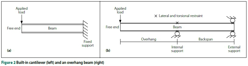
Overhang beams are continuous beams where the end span is cantilevered. The main difference between the cantilevered segment of a built-in cantilever and overhang beam is the warping restraint at the support. With a built-in cantilever, warping is prevented, whereas in an overhang beam, not only is warping allowed, but warping also depends on the relative stiffness of the adjacent span. The LTB stiffness of the adjacent span depends on the size of the beam, the laterally unbraced length, and the loading on that segment.
Timoshenko and Gere (1961) proved that it was possible to formulate a closed-form solution for elastic lateral-torsional buckling for both a simply supported beam and a built-in cantilever. They considered an unbraced built-in cantilever with a point load at the tip of the cantilever at the shear centre. The solution depends on the length, the torsional stiffness and warping rigidity of the beam. Elastic LTB refers to buckling that occurs without permanent deformation and depends on the lateral slenderness of the beam. With elastic LTB the yield strength and residual stresses are not considered. In addition, with this model the interaction with local buckling or distortional buckling is not considered.
Kirby and Nethercot (1979) introduced an effective length factor to account for the various support and loading conditions possible in cantilevers and overhang beams. Currently SANS 10162-1 (SANS 2011) uses Equation 1 to determine the LTB capacity of a beam. This formula is based on Timoshenko and Gere's (1961) simply supported beam equation, but modified to incorporate an effective length factor. The effective length factors depend on the restraint conditions for rotation about the minor axis and the warping restraint at the supports, and also on the destabilising or normal load conditions. No provision is made for the effect of the lateral buckling length of an adjacent span or the torsional parameter (defined later) on the effective length factor. Even though Equation 1 is based on a simply supported beam, SANS 10162-1 (SANS 2011; also BS 2008 and Ziemian 2010) uses this equation in conjunction with an effective length factor for cantilevers and overhang beams (a>2 = 1 in the case of a cantilever with no effective lateral support for the beam at the free end).
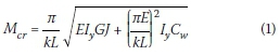
Where:
Mcr = elastic critical moment of a beam segment
k = effective length factor (K in SANS 10162-1)
L = length of beam segment between lateral restraints, projecting length of cantilever
E = elastic modulus of steel
Iy= moment of inertia about y-axis (minor axis)
G = shear modulus of steel
J = St Venant torsion constant of a cross-section
Cw = warping torsional constant.
LIST OF NOTATIONS
A = Design equation factor
B = Design equation factor
C = Torsional rigidity (Timoshenko & Gere 1961), design equation factor
C1= Warping rigidity (Timoshenko & Gere 1961)
C1 & C2= Expressions used to calculate the buckling moment (Andrade et al 2007)
Cw= Warping torsional constant
d = Distance between flange centroids (Trahair et al 2008)
E = Elastic modulus of steel
fyi = Lower yield strength
fyu= Upper yield strength
G = Shear modulus of steel
hs= Distance between flange centroids (Andrade et al 2007), equivalent to "d"
I = Interaction factor (Essa & Kennedy 1994)
It= St Venant torsion constant of a cross-section (European practice)
Iw= Warping torsional constant (European practice)
Iy = Moment of inertia about y-axis, the minor axis (RSA and North American practice)
Iz= Moment of inertia about z-axis, the minor axis (European practice)
J = St Venant torsion constant of a cross-section (RSA and North American practice)
K = Torsional parameter of a segment (Trahair et al 2008)
K = Torsional parameter of a segment (Andrade et al 2007)
k = Effective length factor
kw= Effective length factor for end warping restraint (Andrade et al 2007)
kz= Effective length factor for end rotations about the z-axis, minor axis (Andrade et al 2007)
L = Length of beam between lateral restraints, length of cantilever
Lb= Length of the backspan segment
Lc= Length of cantilever (overhang) segment
Mb= Critical moment of the backspan segment that is free to warp (Essa & Kennedy 1994)
Mc= Critical moment of cantilever segment that is free to warp (Essa & Kennedy 1994)
Mcr= Elastic critical moment of a beam
Pcr= Elastic critical buckling load of a cantilever (Timoshenko & Gere 1961)
Q = Critical buckling point load at free end of cantilever (Trahair et al 2008)
yQ= Distance between the shear centre and the load applied (positive below the shear centre) (Trahair et al 2008)
Zg= Distance between shear centre and load applied (positive above the shear centre) (Andrade et al 2007)
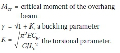
γ = Buckling parameter
γ2= Dimensionless factor (Timoshenko & Gere 1961)
κ = Ratio of the smaller moment to the larger moment at opposite ends of the unbraced length
ε = Dimensionless load height parameter (Trahair et al 2008)
w2= Equivalent moment factor (C in American literature)
Equation 1 uses one effective length factor. It will be seen below that Andrade et al (2007) employ two different effective length factors for the torsional and warping stiffness terms.
Recent investigations to determine the Mcruse different approaches to obtain the LTB capacity of cantilevers and overhang beams, and do not use the effective length factors published in the codes and by Ziemian (2010). Most notably were the investigations of Andrade et al (2007) and Trahair et al (2008) which are discussed below. Special purpose computer programs, such as PRFELB (Trahair et al 2008) are also available to compute Mcr.
Andrade et al method
Andrade et al (2007) investigated cantilever beams that were either prevented from warping (NW) or free to warp (FW) at the support (in the latter case a cantilever with unrestrained flanges in the longitudinal direction). Thus the effect of an adjacent span was considered, but not the extent of the effect of the LTB stiffness of an adjacent span.
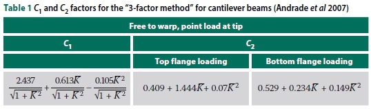
The method proposed by Andrade et al (2007) to determine the critical buckling moment is a rational approach, which extended the "3-factor method" C1, C2 and C3) to include cantilevers and overhang beams. The modified formula for free-to-warp (FW) cantilevers, doubly symmetrical, and for bending about the major axis only, is defined as follows:
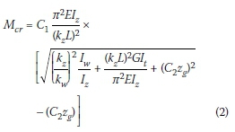
Where:
C1 & C2are factors that depend on the warping restraint, the type of load, the distance between the shear centre and the load applied, and the torsional parameter (see Table 1)
Zg= vertical distance between the shear centre (centroid) and the position of the load applied, measured as positive if the load is applied above the shear centre  and is the dimensionless torsional parameter, 0.1 < Κ < 2.5
hs= distance between flange centroids
kz= effective length factor for end reactions about the minor z-axis (taken as = 2.0)
kw= effective length factor for end warping restraint (taken as = 1.0)
IZ= moment of inertia about the minor z-axis (European equivalent for Iy)
It= torsional constant (European equivalent for J)
Iw= warping torsional constant (European equivalent for Cw)
L = length of the cantilever beam.
Andrade et al (2007) also presented similar tables for cantilevers with warping prevented at the fixed end. (The results from computations with these equations are presented in Figure 1 and Table 2.)
Trahair et al method
Trahair et al (2008) presented an equation for overhanging beams that are free to warp at the support. This equation neglects the magnitude of warping restraint due to the length of the adjacent span. The method by Trahair et al (2008) approximates the buckling capacity of an overhang beam with a point load at the free end with the following equation:
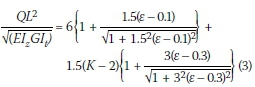
Where:
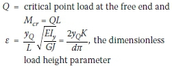
yQ= vertical distance between the shear centre (centroid) and the load applied, positive below the shear centre (or centroid in this case)
d = distance between the flange centroids = h in Andrade et al (2007)
K = torsional parameter of a segment = Κ in Andrade et al (2007)
Iy= moment of inertia about the y (minor) axis = Izin Andrade et al (2007).
Trahair et al (2008) also presented formulas for cantilevers with warping prevented at the fixed end. (The results from computations with these equations are also presented in Figure 1 and Table 2.)
Timoshenko and Gere
The two methods provided above, though limited, did provide insight into the magnitude of buckling capacity expected for overhang beams. Both approaches have a non-dimensional term and a dimensional term- , similar to the built-in cantilever (with point load at the tip shear centre) equation given by Timoshenko & Gere (1961):
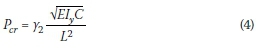
Where:
Pcr= elastic critical buckling load of a built-in cantilever
Y2= dimensionless factor depending on the ratio of 
C = GJ and is the torsional rigidity of a beam
C = ECwand is the warping rigidity of a beam.
Built-in cantilevers
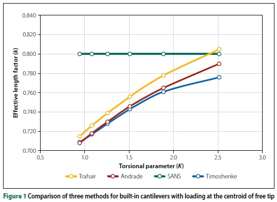
Andrade et al (2007) and Trahair et al (2008) also provide equations for built-in cantilevers. The results derived from these equations could be compared to the equation given by Timoshenko and Gere (1961). A built-in W310 χ 79 beam (equivalent to the South African designation 306 χ 254 χ 79 I) was analysed with different spans with a point load at the free tip centroid. To compare the Mcrresults from the three methods, effective length factors, k, were back-calculated from Equation 1 with the calculated Mcrvalues. The effective length factor values, k, are plotted in Figure 1 against the dimensionless torsional parameter K. For the same beam section (as in this case) a smaller value of K indicates a longer cantilever length (and a larger value of K indicates a shorter cantilever length).
It can be seen that, for this relatively simple built-in cantilever problem, the three methods give similar results. (The effective length value given in codes is a constant.) When analysing built-in cantilevers with loading on the top flange and overhang beams (free to warp at the support) the results from different methods have a larger scatter. See, for example, Van Rensburg and Skorpen (2016). It can also be seen that effective length factors given in codes or in Ziemian (2010) for different cantilevers or overhang beams, with top flange or centroid loading, should not actually be constant values.
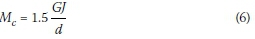
Essa and Kennedy method
A different approach, which did consider the backspan segment, via interaction buckling, was investigated by Essa and Kennedy (1994). They used interaction buckling in their investigation of the LTB of two-span continuous overhang beams. Interaction buckling is a term which describes the LTB of a continuous beam where the buckling capacity of each segment has an influence on the overall buckling capacity. The lateral buckling stiffness of the adjacent segments influences the buckling-critical beam segment (Schmitke & Kennedy 1985). Interaction buckling divides a continuous beam into segments: 'restrained' and 'restraining'. The former is the critical unbraced segment (which could buckle first) and the latter would decrease the effective length of the critical segment. Conversely, the effective length of the non-critical restraining segments would increase due to the restrained critical segment. The concept of interaction buckling of continuous beams is also described in Trahair et al (2008).
Essa and Kennedy (1994) analysed the backspan and overhang segments separately, and concluded that, if the backspan was the critical segment, the effect of interaction buckling is omitted in determining the LTB capacity. This conclusion implies that the backspan segment could influence the buckling capacity of the overhanging segment, but not vice versa. If the overhanging segment was critical, the LTB capacity of that segment (and therefore the overhang beam) was adjusted:

Top flange loading approximation:
Shear centre loading approximation:

Where:
Mc= critical moment of the cantilever segment that is free to warp at the support
Mb= critical moment of the backspan segment that is free to warp at both supports
Lc= length of the unbraced cantilever (overhang) segment
Lb= length of the unbraced backspan segment
d = distance between the flange centroids
w2= 1.75, as both supports are rollers and the end moment ratio becomes zero
I = interaction factor, a function of the ratio of backspan to the overhang span.
For the case of an overhanging beam with a free tip:
Two questions could be raised regarding these formulae provided by Essa and Kennedy (1994). Firstly, according to their simple FE models, the critical moment of the overhanging segment (top flange loading) was independent of the length of the segment, which seems unlikely. Secondly, for small ratios of backspan-to-overhang-lengths  < 0.5 the interaction equation yields unrealistic values. These small ratios are perhaps outside the calibrated range of the authors; however, no limits regarding backspan length to overhang length ratio were specified in the paper.
The Essa and Kennedy (1994) equations are also applied in Table 2 (see page 9).
PHYSICAL EXPERIMENTS
Physical experiments were conducted to determine the buckling capacity of cantilever and overhang beams (Figure 2). Four built-in cantilevers were tested to ensure that the measurements recorded during testing were accurate. In total, 20 experiments were conducted on overhang beams. The beams used for the experiments were IPEAA100 with a constant cantilever/overhang length of 2.5 m. The tests were repeated for both shear centre and top flange loading, with the backspan-to-overhang ratio ranging from 0.5 to 2.5, in increments of 0.5. Comprehensive details of the experimental program are given in Venter (2016).
Overhang beam supports
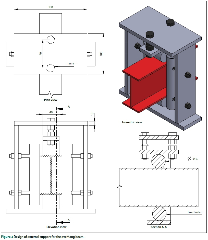
The overhang beam supports were designed to prevent lateral and torsional movement but to allow warping. To this end, rollers were used for the supports and adjustable vertical restraints were added next to the beam to prevent lateral and torsional movement. The vertical restraints were adjustable to account for the slight differences in flange widths for each beam.
The design of the external support (Figure 3) differed slightly from the internal support due to the upward reaction, and a second roller was provided above the beam. The second roller was adjustable to account for the difference in beam height for each beam. The external roller was also fixed to prevent longitudinal movement.
Loading of beams
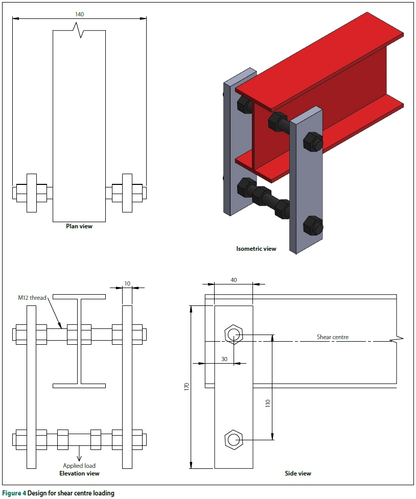
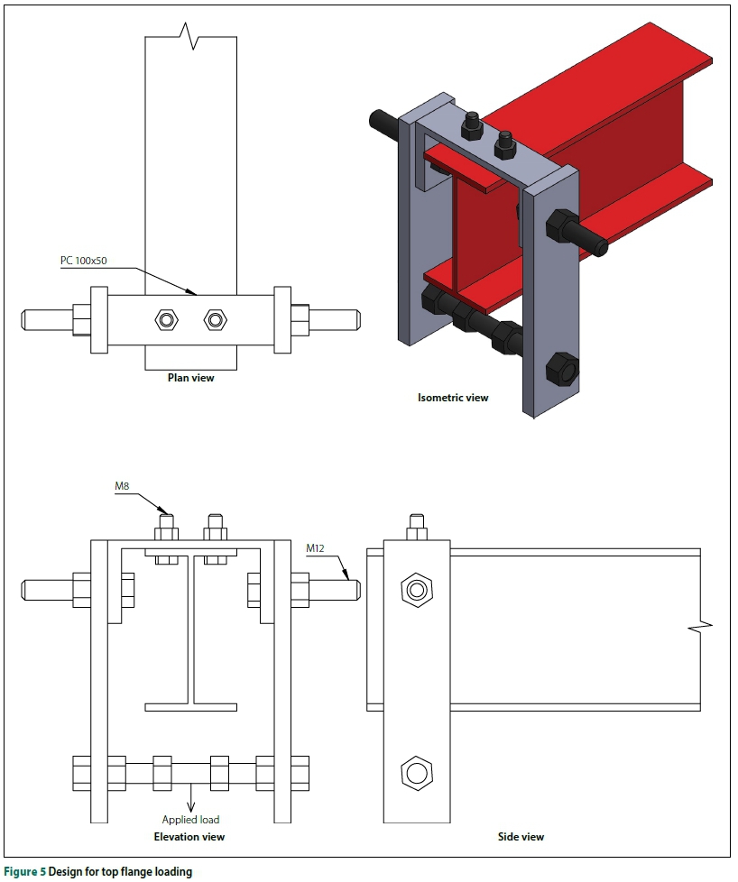
The beams were loaded by a 1 000 litre water tank which was gradually filled and attached either at the shear centre of the beam or on the top flange. The load acted on the shear centre line, and top flange loading did not induce a measurable eccentric loading. The loading mechanism allowed for rotation and twisting of the applied load as the beam deflected and twisted when it buckled, also ensuring that the load applied remained essentially vertical during testing. Figures 4 and 5 show the design for the shear centre and top flange loading, respectively. A one-tonne calibrated load cell was attached to the bottom of the loading mechanism to measure the load. The data was logged and stored via a graphical logger (Graphtec Model GL220).
Buckling loads from experiments
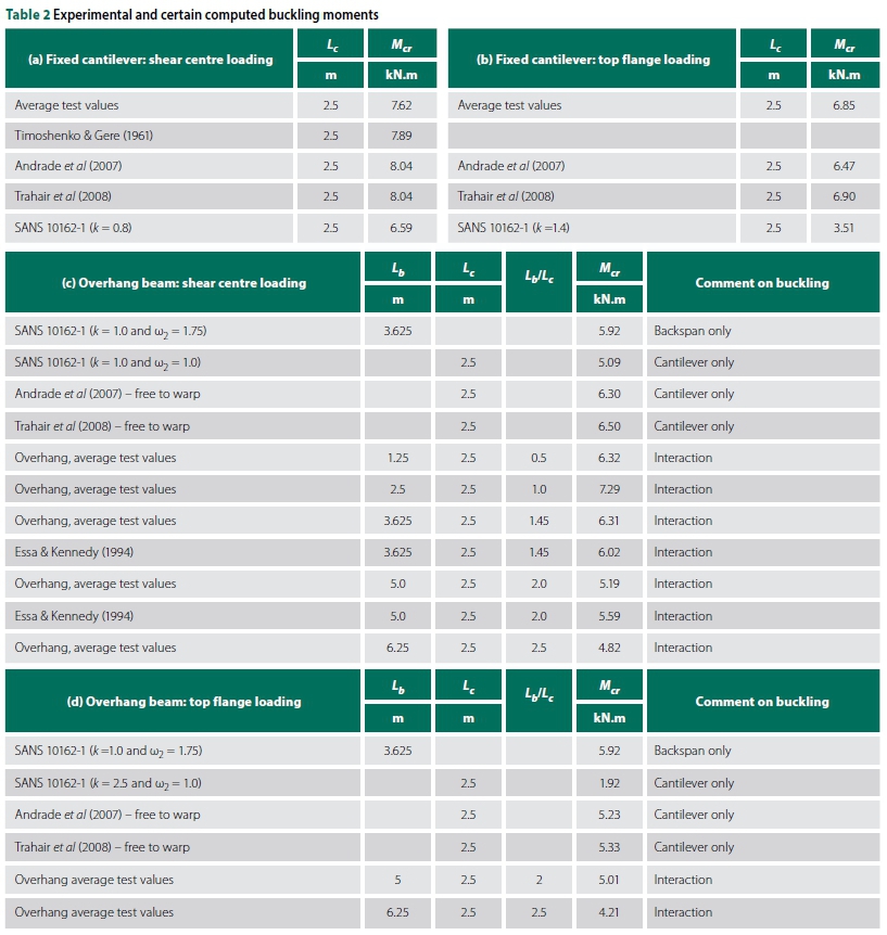
The critical buckling moments, Mcr, obtained from the experiments are shown in Table 2. These loads were based on the maximum load obtained during the tests. Before testing, the beam dimensions were measured. It was noted that the beams were somewhat larger than the nominal dimensions given in the Southern African Steel Construction Handbook (SASCH 2013), but were within the allowable tolerances for hot-rolled sections as per the SASCH (2013).
The out-of-straightness of the beams, as well as the material properties, was measured. See the discussion below.
For reference purposes, Mcrvalues were also calculated for certain cases. The following material values were used: E = 200 GPa and G = 77 GPa. The geometrical properties listed in the SASCH (2013) were employed.
For the built-in (fixed) cantilever with an unbraced tip and with shear centre point loading at the tip (Case Tb2a), the average test results are indicated. Theoretical values were calculated with the Timoshenko and Gere (1961) formula (Equation 4) given above, formulas given in the Andrade et al (2007) and Trahair et al (2008) publications, as well as the design code formula with an effective length factor = 0.8. The values are in reasonable agreement with a more conservative code value.
For the built-in cantilever with an unbraced tip and with top flange point loading at the tip (Case Tb2b), the average test results are indicated. Theoretical values were again calculated with the formulas given in the Andrade et al (2007) and Trahair et al (2008) publications, as well as the design code formula with an effective length factor = 1.4. The code value appears to be very conservative.
In order to provide a perspective on the Mcrvalues obtained from the tests for overhang beams with an unbraced tip and with shear centre point loading at the tip (Case Tb2c), the code was applied to separately investigate the capacity of the backspan and overhang segments. Backspan:
As the interior support is considered to be hinged and the unbraced backspan (effective length factor = 1) is only loaded with the cantilever moment, κ = 0 and thus ω2 = 1.75. With an Lb= 3.625 m the code gives an Mcr= 5.92 kN.m. Overhang segment: For a continuous cantilever with a "fork" support, the effective length factor = 1 (and W2= 1.0), and with Lc= 2.5 m the code gives Mcr= 5.09 kN.m.
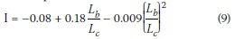
For Case Tb2c, theoretical values were calculated with the formulas of Andrade et al (2007) and Trahair et al (2008) (see Equations 2 and 3) and are indicated in Table 2. The method of Essa and Kennedy (1994), which considers interaction buckling, was applied (see Equations 5 to 9) and the Mcrvalues indicated. Lastly, the average test results are shown and it could be observed how Mcrdecreases with an increase in Lb.
For overhang beams with an unbraced tip and with top flange point loading at the tip (Case Tb2d), the code was applied to investigate the capacity of the overhang segment. (The Mcrvalue for the backspan is not affected by the height of load application on the cantilever.) Overhang segment: For a continuous cantilever with a "fork" support and destabilising loading, the effective length factor = 2.5 and with Lc= 2.5 m the code gives Mcr= 1.92 kN.m. Theoretical values were calculated with the formulas of Andrade et al (2007) and Trahair et al (2008) (see Equations 2 and 3) and are also indicated in Table 2. The code value again appears to be extremely conservative.
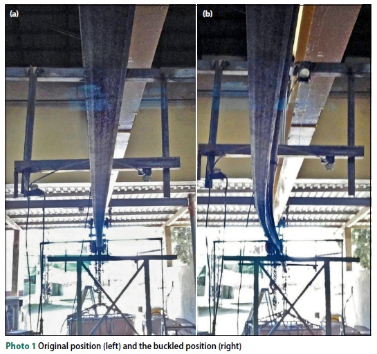
The scatter in the buckling loads is attributed to variations in initial out-of-straightness, beam sizes and material properties (see below) and, in addition, to the surface contact between the beam and the supports (rollers and vertical restraints) which caused additional friction when the beam was loaded. The additional friction in the flanges of the beam increased the warping resistance, causing the beam to resist a larger load before buckling occurred. Slight initial out-of-straightness also contributed to a lower critical moment. Photograph 1 shows the original and buckled shape of the back-span segment of an overhang beam.
Material properties
The material properties of the tested beams were determined (Venter 2016) via tensile ('dog bone') testing. Nine samples were cut from the web of an unloaded beam. The samples were loaded until fracture. The average lower yield strength fytwas 362.8 MPa, and the upper yield strength fyuwas 377.8 MPa, according to the ISO 6892-1 (ISO 2009) standard.
The calculated elastic modulus, via the tangent method, was 204.3 GPa. These values were used to calibrate the FE solid element models with the fixed cantilever experimental work.
Geometrical properties
Venter (2016) comprehensively documented the variations in beam dimensions and out-of-straightness. For such a small section, the allowable tollerances have a significant impact on the stiffness properties of the member. Most of the beams had flanges that were somewhat tapered. The slightest taper towards the web, combined with flanges and webs thicker than the nominal dimensions dramatically increases, for instance, the St Venant torsion constant. Maljaars et al (2004, Figure 7) explains the significant role of the flange and web junctions on the St. Venant torsion constant.
FINITE ELEMENT METHOD
Finite Element (FE) analysis served two purposes in this study - firstly to expand the scope of the investigation, and secondly to obtain a relationship between the buckling capacities and the beam buckling parameters. The solid element models were first calibrated to the physical models to verify the accuracy and consistency of FE modelling when solving LTB problems, and then other size beams and overhang ratios were considered.
The FE program ABAQUS (2015) was used with the Buckling Analysis solver. The Buckling Analysis solver determines an Eigenvalue using the bifurcation method. An Eigenvalue is a load factor relative to the load applied to the model, which illustrates the ratio between the buckling load and the load applied. This FEM approach to obtain a buckling load factor would include the possibility of combined LTB and distorsional buckling of the overhang beam (Bradford 1994).
Element properties
In the calibration exercise the measured properties of the steel were used to verify the FE models with the physical tests. The material properties used were: fy= 362.8 MPa, E = 204 GPa and G = 77 GPa. For all further analysis on other beams other than IPEaa100 the solid elements were assigned material properties of 350W steel (f = 350 MPa), with E = 200 GPa and G = 77 GPa. Residual stresses can reduce the critical moment of the beam below the theoretical elastic buckling moment. However, the effect of residual stresses decreases as the slenderness of the beam increases. Therefore, the FE models do not include residual stresses.
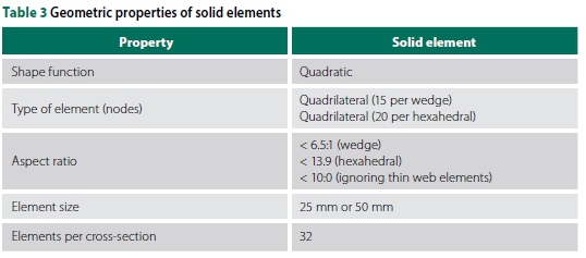
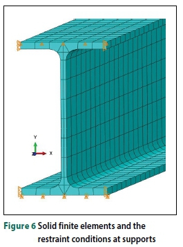
The geometric properties of the solid elements are provided in Table 3. Both hexahedral (20 nodes) and wedge (15 nodes) elements were used to improve the accuracy of the mesh, especially at the interfaces between the web and the flanges. Solid elements have six degrees of freedom per node. Comparitive analyses with the thickness and width of the flange and web divided into multiple layers (mesh refinement) resulted in a negligible difference in the critical moment of the beam. Refinement of the mesh also did not improve the results. Therefore, to reduce computation time and the aspect ratio, only the web thickness was divided into two layers. Figure 6 shows the boundary conditions and the solid element IPEaa100 model.
Model dimensions analysed
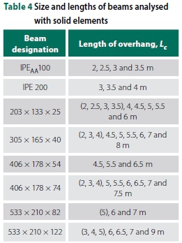
The elastic and inelastic ranges of buckling depend on the effective length of the beam. The ranges were defined by 0.67 Mp and 0.9 Mpfor elastic and inelastic, respectively. The effective length factors provided by SANS 10162-1 (SANS 2011) were utilised to determine the length of the beam required for elastic LTB. The size and overhang lengths of the beams modelled using solid elements are provided in Table 4. The values in parenthesis refer to models with top flange loading only, which have shorter lengths but remain in the elastic range (due to larger effective length factors).
SENSITIVITY ANALYSIS
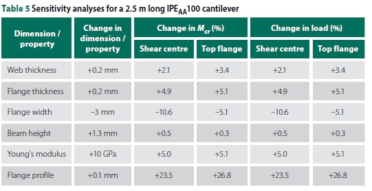
The cross-sections of the tested IPEaa100 beams were found to vary, and a sensitivity analysis was performed to assess the effect of varying the beam cross-section geometry on the buckling capacity. The sensitivity analyses were based on Equation 1 and were compared to the ideal fixed cantilever beam. For an IPEaa100 cantilever beam with a length of 2.5 m, the buckling capacities were 6.59 kN.m and 3.51 kN.m for the shear centre and top flange loading, respectively. Table 5 presents the results of the sensitivity analyses.
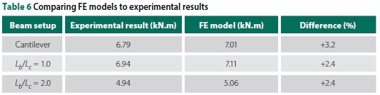
The nominal dimensions and properties of the I-beam are based on a parallel flange section. It was established that some of the beams had thicker flanges than the nominal flange thickness, and also a taper. For sections with the thicker and tapered profiles of the flange this fact was deemed to have the largest influence on the buckling capacity. The dimensions of the beams tested were measured and were used to calibrate the solid element models, together with the measured material properties. The results of the calibrated models are provided and compared to the experiments in Table 6. With a maximum difference of 3.2%, it was found that the solid element models are an accurate numerical method to solve LTB problems. However, as previously stated, to achieve consistency the parametric study using FE solid element models was based on nominal dimensions and properties provided by the SASCH (2013).
ANALYSIS OF RESULTS
Analysis of solid element results
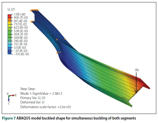
For a given backspan-to-overhang ratio, either the overhang segment or the backspan segment, or both segments together, dictate the critical buckling mode. For example, an IPEaa100 beam with a 2.5 m overhang length underwent simultaneous buckling in both segments if  = 1.0. This was noted in both the physical experiments and FE solid element modelling, as illustrated in Figure 7. The straight line in Figure 7 serves as a reference line to indicate buckling in both segments.
The results of the FE modelling of the 203 χ 133 χ 25 I-beam are shown in Graphs 1 and 2. The complete results of all the beams analysed are provided in Appendix A of Venter (2016). The discussions and conclusions that follow were based on all the analyses conducted, which apply to all beam sizes and lengths.
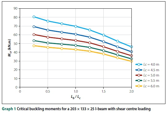
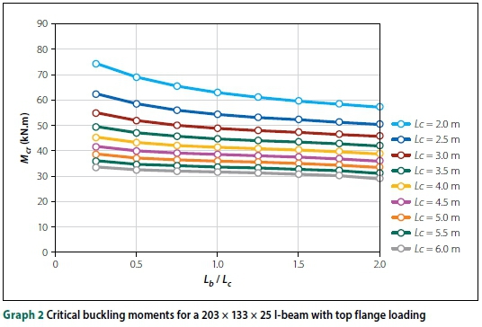
■ Increasing the back span ratio Lb/ Lcdecreased the critical moment. However, for top flange loading, this observation was less profound.
■ The buckling capacity became less sensitive to the overhang length Lcas the ratio Lb/Lcincreased. This statement is only for shear centre loading.
■ Top flange loading significantly decreased the buckling capacity of the beam.
■ The reduction in buckling capacity, due to top flange loading, diminished as the overhang length Lcincreased.
■ These observations were consistent with all the beam sizes analysed.
With various overhang lengths Lc, Graphs 1 and 2 illustrate the observations made above for a 203 χ 133 χ 25 I-beam with shear centre and top flange loading, respectively.
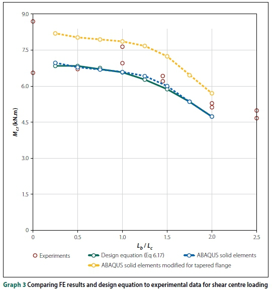
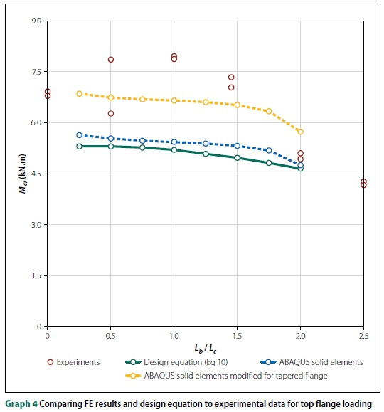
Comparing FE results to experiments
To model the physical test results was a challenge, due to the scale of the experimental setup, the dimensional and material variations of the beams, the exact restraint conditions provided to the beam and, lastly, the method of load application (Venter 2016).
The experimental work (IPEaa100 with an overhang length of 2.5 m) and FE solid element ABAQUS models are compared in Graphs 3 and 4. Two FE models were done, firstly one with the nominal design dimensions and parallel flanges, and then a model with the measured cross-section dimensions (slightly larger) and tapered flanges. It was clear that the beam cross-section has a large impact on the buckling capacity of a beam, as justified by FE solid element modelling.
DESIGN EQUATION
To compare the FE models to the physical models, a single-sized beam with a fixed overhang length was used. However, to draw conclusions based on all the FE analyses conducted, a new approach was required to incorporate these additional parameters.
The closed-form solution of an I-section beam with lateral and torsional restraints, and under uniform bending, can be written as follows:
The solution can be transformed to take the following term:
Where:
The length of the overhang and the size of the beam were combined using the torsion-al beam parameter K. With this approach, all of the models were comparable directly with a given loading condition.
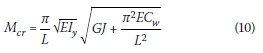
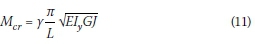
The cantilever formula (Equation 4) given by Timoshenko and Gere (1961) was used as a basis on which the design equations were expanded. Equation 10 is the basic form of the design equation by Timoshenko and Gere (1961). The equation has two parts, a beam parameter relating the properties of the beam to the buckling capacity  and a non-dimensional buckling parameter, which takes into account the load height, support conditions and the backspan-to-overhang ratio.
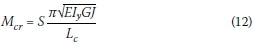
Where: S is a non-dimensional buckling parameter.
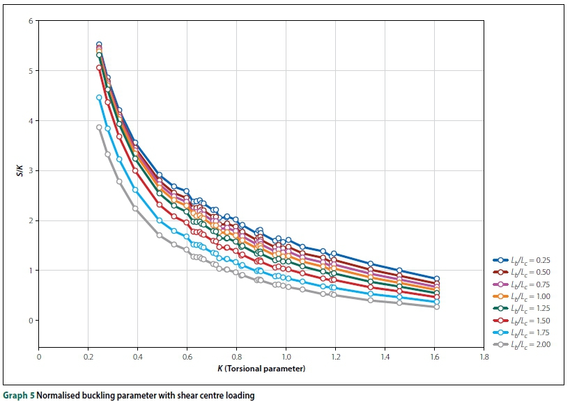
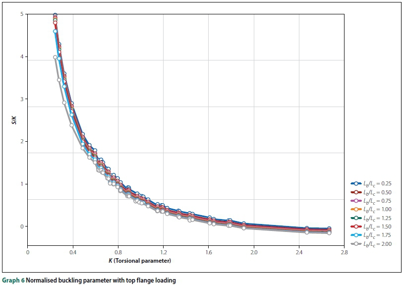
Rewriting Equation 10 provides a relationship between the critical moment Mcrand the nondimensional buckling parameter S, given by Equation 13. However, by plotting S against K no discernable relationship existed between these two parameters. Instead, the non-dimensional part of the equation was 'normalised' by dividing it with K (Equation 14). Graphs 5 and 6 illustrate the relationship between the 'normalised' non-dimensional buckling parameter (S/K) and the torsional beam parameter K for shear centre and top flange loading, respectively.
The relationships between K and S/K were power functions, with different co-factors depending on Lb/Lc(Equation 15).
Rewriting the equation to obtain the buckling parameter S and adding an adjustment factor C, the design equation takes the form of Equation 16. The purpose of factor C was to ensure that the design equations were not too conservative (up to 13%) and overestimated by less than 1%.
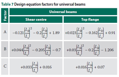
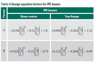
A, B and C are second-degree polynomial functions of Lb/Lcand are defined in Tables 7 and 8. The non-dimensional buckling parameter S depends on the size of the beam, length of overhang, backspan-to-overhang ratio and the distance between the applied load and shear centre (load height).
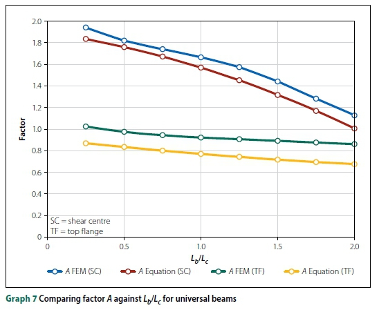
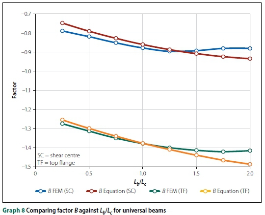
To improve the accuracy of the design equations, the IPEaa100 beams were separated from the 'universal' beams. Universal beams refer to the beams typically manufactured in South Africa, i.e. the 203 χ 133 χ 25 I-beam. Plotting A and B against Lb/Lcrevealed a quadratic function (Ax2+ Bx + C, with x = Lb/Lc) relating the parameters, as shown in Graphs 7 and 8 (for universal beams). The curves for IPEaa100 were similar, with slightly different factors for A and B.
Comparing design equations
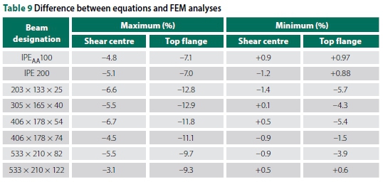
Table 9 illustrates the maximum and minimum differences between the design equations and the results obtained from the FE solid element modelling. These comparisons apply to all overhang lengths and backspan-to-overhang ratios analysed. A negative value implies a conservative result, while a positive value overestimates the buckling capacity. Note that the design equations were consistent regarding the size of the beam. In summary, the overestimate is always less than 1%.
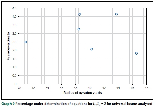
For the specific case of Lb/Lc= 2 and Lc= 6 m the percentage under-determination of the equations' values of the FEM values against the minor radius of gyration, ry, is shown in Graph 9 for the universal beam sections modelled. No trend could be detected.
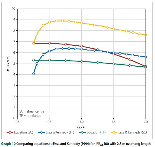
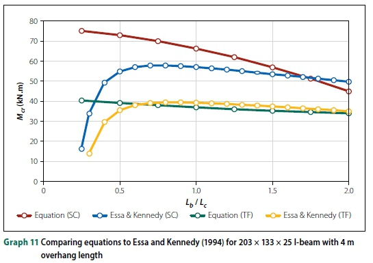
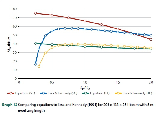
Since Essa and Kennedy (1994) investigated the effect of the backspan on LTB capacity, it is worth comparing the FE results to their design method. Graphs 10, 11 and 12 illustrate the comparison for an IPEaa100 beam with a 2.5 m overhang and a 203 χ 133 χ 25 I-beam with a 4 m and 5 m overhang, respectively. As depicted in the graphs, the buckling capacity for top flange loading was highly variable when using the method proposed by Essa and Kennedy (1994). They stated that, for top flange loading, the critical moment of the overhang was independent of the overhang length. Thus, the buckling capacities were either over-conservative or overestimated, based on the size of the beam. For small backspan to overhang ratios (Lb/Lc< 0.75), their equation resulted in a decrease in buckling capacities, which is clearly incorrect as this is the opposite of what was observed in both types of FE analyses and physical experiments. The data of Essa and Kennedy (1994) in the graphs were according to the equations they published, but they clearly did not intend their formulae to be used for small Lb/Lcratios.
Design examples
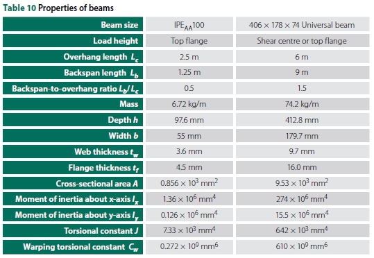
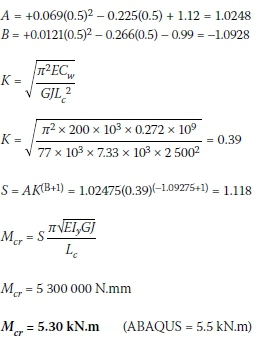
Three examples are provided to illustrate how these design equations could be used. These examples illustrate the ease with which the critical moment of an overhang can be calculated. The examples are for an IPEaa100 beam (top flange loading) and a 406 χ 178 χ 74 I-beam (for both shear centre and top flange loading). The beams were provided with lateral and torsional restraints at the supports, whereas the load was applied to the free end of the overhang beam. Table 10 illustrates the nominal properties of the two design beams according to the SASCH (2013).
IPEAA100:
From Table 8 for top flange loading:
406 χ 178 χ 741:
From Table 7 for shear centre loading:
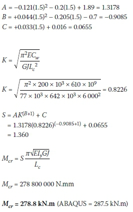
The calculations were repeated for top flange loading.
Table 11 compares the proposed design equation with the ABAQUS FE solid element models, other publications and the current SANS 10162-1 (SANS 2011) method.
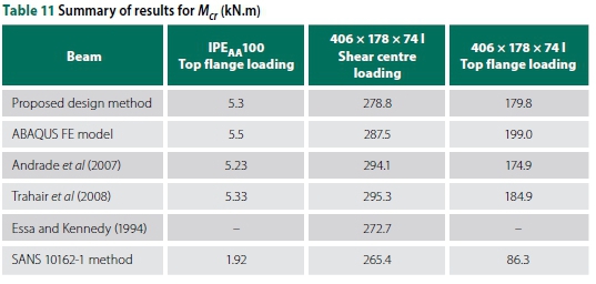
From Table 11 it could again be observed that the method of SANS 10162-1 (SANS 2011) produces extremely conservative values for top flange loading. The application of the Essa and Kennedy (1994) method did not produce realistic results for top flange loading.
CONCLUSIONS AND RECOMMENDATIONS
The experimental program posed several challenges, as discussed, which led to a significant scatter in the results. Nevertheless, the experimental work illustrated the buckling behaviour of overhang beams and produced useful data for benchmarking against other methods and the FEM results. The FEM method with solid elements (rather than shell elements) was successfully implemented for this buckling problem and also demonstrated the LTB behaviour of beams. The results were effectively benchmarked against the experimental work and other research data. Many structural steel design codes, including SANS 10162-1 (2011), do not take the length of the backspan into account when calculating the LTB capacity of an overhang beam. Andrade et al (2007) and Trahair et al (2008) formulated equations for overhang beams by considering free-to-warp cantilevers, but neglected the effect of the length of the backspan. Certain methods have extended the solution of Mcrfor single- and double-span beams for different boundary and loading conditions by applying a γ factor, which is a function of more than the K parameter only. These extended solutions, however, do not include the backspan-to-overhang ratio Lb/Lc. It was shown that the simplicity of the effective length approach leads to extremely conservative Mcrvalues for top flange loading.
This study investigated the effect of the backspan on overhang beams with supports which prevent lateral and torsional movement but allow warping. Based on the physical experiments and FE analyses, increasing the ratio of backspan to overhang reduces the lateral-torsional buckling capacity of an overhang beam. Also, increasing the overhang length has an adverse effect on the buckling capacity. For shear centre loading, the buckling capacity becomes less sensitive to the overhang length Lcas the ratio Lb/Lcincreases. A proposed extended form of the factor γ specifically formulated for overhang beams is given in Equation 14. The proposed design method was validated using experimental investigations and verified by FE analysis.
While the limitations of the study are acknowledged in terms of the physical testing of only one beam size, support condition limited to lateral and torsional restraint, and only elastic buckling investigated, the authors believe that this work could lead to the start of more accurate assessment of the capacity of overhang beams. Further testing and analysis for other support, bracing and loading conditions could result in further refinement and in increasing the scope of the proposed design approach.
REFERENCES
ABAQUS 2015. ABAQUS analysis user's manual, Version 6.13. ABAQUS, Inc. [ Links ]
Andrade, A, Camotim, D & Costa, P P 2007. On the evaluation of elastic critical moments in doubly and singly symmetric I-section cantilevers. Journal of Constructional Steel Research, 63(7): 894-908. [ Links ]
Bradford, M A 1994. Elastic distorsional buckling of overhanging beams. Report No. R-337. University of New South Wales, Sydney, Australia. [ Links ]
BS (British Standard) 2008. BS 5950-1:2000. Structural Use of Steelwork in Building. Part 1. Code of Practice for Design - Rolled and Welded Sections. London: British Standards Institution. [ Links ]
Essa, H S & Kennedy, D J L 1994. Design of cantilever steel beams: Refined approach. Journal of Structural Engineering,120(9): 2623-2636. [ Links ]
ISO (International Organization for Standardization) 2009. ISO 6892-1:2009. Metallic Materials -Tensile Testing. Part 1. Method of Test at Room Temperature. Brussels: European Committee for Standardization. [ Links ]
Kirby, P A & Nethercot, D A 1979. Design for Structural Stability. New York: Halsted Press. [ Links ]
Maljaars, J, Stark, J W B & Steenbergen, H M G M 2004. Buckling of coped steel beams and steel beams with partial endplates. HERON, 49(3): 233-271. [ Links ]
SASCH 2013. The Southern African Steel Construction Handbook, 8th ed. Johannesburg: SASCH. [ Links ]
SANS (South African National Standard) 2011. SANS 10162-1. The Structural Use of Steel - Part 1. Limit-states Design of Hot-rolled Steelwork. Pretoria: SABS Standards Division. [ Links ]
Schmitke, C D & Kennedy, D J L 1985. Effective lengths of laterally continuous, laterally unsupported beams. Canadian Journal of Civil Engineering, 12(3): 603-616. [ Links ]
Timoshenko, S P & Gere, J M 1961. Theory of Elastic Stability. New York: McGraw-Hill. [ Links ]
Trahair, N S, Bradford, M A, Nethercot, D A & Gardner, L 2008. The Behaviour and Design of Steel Structures to EC, 4th ed. New York: Taylor & Francis. [ Links ]
Van Rensburg, B W J & Skorpen, S A 2016. Effective length factors for the lateral torsional buckling of cantilever beams. In: Zingoni, A (Ed.), Insights and Innovations in Structural Engineering, Mechanics and Computation. London: CRC Press. [ Links ]
Venter, S H 2016. Effect of the adjacent span on the lateral-torsional buckling capacity of overhang beams. MEng Dissertation. University of Pretoria. [ Links ]
Ziemian, R 2010. Guide to Stability Design Criteria for Metal Structures, 6th ed. Hoboken, NJ: Wiley. [ Links ]
 Correspondence:
SIMON H VENTER
SRK Consulting South Africa
265 Oxford Road
Illovo 2196
Johannesburg
South Africa
T: +27 11 441 1204
Department of Civil Engineering
University of Pretoria
Private Bag X20
Hatfield 0028
Pretoria
South Africa
E: shventer@srk.co.za / simon.h.venter@gmail.com
SARAH A SKORPEN
Department of Civil Engineering
University of Pretoria
Private Bag X20
Hatfield 0028
Pretoria
South Africa
T: +27 12 420 2196
E: sarah.skorpen@up.ac.za
PROF BEN WJ VAN RENSBURG
Department of Civil Engineering
University of Pretoria
Private Bag X20
Hatfield 0028
Pretoria
South Africa
T: +27 12 420 2439
E: ben.vanrensburg@up.ac.za

SIMON H VENTER is a Candidate Civil Engineer who graduated from the University of Pretoria with a Bachelor's degree in Civil Engineering in 2015 and a Master's degree in Structural Engineering in 2017. Simon works as a consulting engineer at SRK Consulting, focusing on hydraulic structures, earthworks and structural design. He has been involved in the design of projects in the fields of wastewater treatment works, effluent water storage, water conveyance structures and ancillary dam structures, including steel gantries and construction supervision of various parts of the works.

SARAH A SKORPEN (PrEng, MIStructE) spent nine years working for the Buildings and Structures Division of SSI before joining the Structures Division of the Department of Civil Engineering at the University of Pretoria in 2011. She has obtained an MEng (Structural Eng) and is completing her doctoral studies on integral bridges.

PROF BEN WJ VAN RENSBURG (PrEng, FSAICE), is a retired professor in the Department of Civil Engineering, University of Pretoria, in the field of Structural Engineering. He started his career in consulting engineering and worked in a research organisation, subsequently joining the University of Pretoria. He obtained BSc and MSc degrees in Civil Engineering from the University of Pretoria, an MSc (Structural Engineering) from the University of Southampton, United Kingdom, and a PhD (Civil Engineering) from the University of Pretoria.

