


Services on Demand
Article
 English (pdf)
 Article in xml format
 Article references
Indicators

Related links
-
 Cited by Google
 -
 Similars in Google
Share

 Permalink
Journal of the South African Institution of Civil Engineering
On-line version ISSN 2309-8775
Print version ISSN 1021-2019
J. S. Afr. Inst. Civ. Eng. vol.61 n.3 Midrand Sep. 2019
http://dx.doi.org/10.17159/2309-8775/2019/v61n3a1
TECHNICAL PAPER
Developing a hydraulic jump length model on horizontal rough beds
F Yousefi; J Mozaffari; S A M Movahed
ABSTRACT
Hydraulic jumps play an important role in the dissipation of kinetic energy downstream of hydraulic structures. The roughness of the stilling basin increases energy loss and will affect the hydraulic jump length. In this research, to estimate hydraulic jump length and consider roughness, a semi-analytical equation with unspecified coefficient was developed. Then, 244 sets of laboratory data were used to determine the coefficient of equation. The first series of data was related to a flume with a width of 20 cm and Froude number in the range of 1.1 to 5. The second series of data was obtained from a flume with a width of 50 cm and Froude number in the range of 1.02 to 9.19. USBR data was also used to increase the Froude number range as the third series of data. The results showed that the hydraulic jump length obtained from this model is a function of upstream and downstream depths, upstream Froude number, and bed roughness. It was found that the hydraulic jump length obtained from this model has an error of about 8% in comparison with observational values. In addition, according to the model, increasing roughness will reduce the length of the hydraulic jump.
Keywords: hydraulic jump, bed roughness, Buckingham theorem, energy dissipation, Froude number
INTRODUCTION
A hydraulic jump causes kinetic energy dissipation downstream of the hydraulic structures, whenever the flow regime is changed from supercritical to subcritical flow. Stilling basins are considered for energy dissipation to reduce flow energy and create conditions for the occurrence of hydraulic jump in a specific position (Jain 2001). A significant parameter to determine hydraulic jump length is the bed roughness. The results of previous studies have shown that increasing the bed roughness may cause more energy dissipation and, accordingly, may change the hydraulic jump length. Peterka (1984), in the USBR laboratory, presented a graph (Lj/y2 vs Fr 1) to determine hydraulic jump length based on numerous experiments in some channels. Ead and Rajarantnam (2002) investigated hydraulic jump over corrugated aluminium beds, and developed an empirical model. They found that hydraulic jump length over corrugated bed surfaces was approximately half the classical jump length. Izadjoo and Shafai-Bejestan (2007) studied hydraulic jump over four corrugated beds. Pagliara et al (2008) determined an equation for hydraulic jump length over both uniform and non-uniform rough beds in horizontal channels. In recent years, Chanson (2009), Alikhani et al (2010), Nasr Esfahani and Shafai Bajestan (2012), Imran and Akib (2013), and Riazi and Jafari (2014) have studied the effect of drop and barrier height, divergence angle of stilling basins and rough and corrugated bed on the characteristics of hydraulic jump and energy dissipation using dimensional analysis. Kumar and Lodhi (2016) investigated the effect of bed roughness heights on the characteristics of a hydraulic jump. They concluded that the bed roughness height has no considerable effect on hydraulic jump characteristics. Due to the impact of roughness on hydraulic jump, the main aim of this study was to develop a new model to estimate hydraulic jump lengths on horizontal rough beds using dimensional analysis and physical model tests.
MATERIALS AND METHODS
Dimensional analysis
Prior to dimensional analysis, effective factors in physical phenomena should be determined. In the following, the parameters affecting hydraulic jump length will be determined using the momentum equation (Figure 1). The following equation can be written:
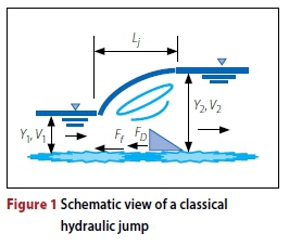

Where: F1and F2 are the hydrostatic pressure forces on the sides of the control volume between sections 1 and 2, respectively, Ff is the friction force, and FD is the drag force due to the obstructions in the flow path or deformation of the channel section.
By assuming a rectangular cross-section with a width B and without obstruction in the flow path, Equation 2 can be written as follows:
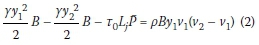
Where: y1 and y2are the alternate depths, Vi and V2 are the velocities, Q is the flow discharge, P is the average wetted perimeter perpendicular to flow direction, Lj is the jump length parallel to the channel bed, and Tq is the average shear stress between sections 1 and 2. By replacing γ by its equivalent (pg) and an average shear stress by its equivalent (apv2), Equation 3 can be written:
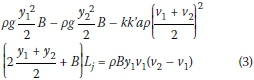
In Equation 3, correction factor (k) is taken into account in terms of the curvature of water surface between sections 1 and 2, and for calculation of the control volume at this distance. The correction factor k is also considered for taking into account the effect of air mixing and the reduced water volume at this distance. In addition, the coefficient "a" depends on the bed roughness. In the third term of Equation 3, y1and y2can be replaced by MB and NB, respectively. After sorting and simplifying, and by using Ljin terms of the other parameters, Equation 3 can be written as follows:
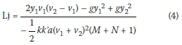
Where: g is gravity acceleration, and dimen-sionless parameter a mainly depends on bed roughness ks. Although in Equation 4 the values of parameters a, k, k', M and N are unknown, the result of this equation shows the dependent factors on the jump length. Both dimensionless parameters of k and k' mainly depend on viscosity and flow velocity (or Reynolds number). In addition, the dimensionless parameters of M and N depend on the flow depth and velocity in sections 1 and 2. Regarding the components of Equation 4, these can be written as follows:

In open channel flows, when the Reynolds number is greater than 2qqq, the effect of viscosity can be avoided (Hager and Bremen 1989). Therefore, Equation 5 can be written as follows:
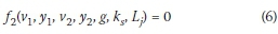
Equation 6 changes to an analytical equation using dimensional analysis through the Buckingham theorem. However, an unspecified coefficient is created in dimensional analysis that can be determined using experimental data and non-linear regression in 3D Table Curve software.
Laboratory flumes
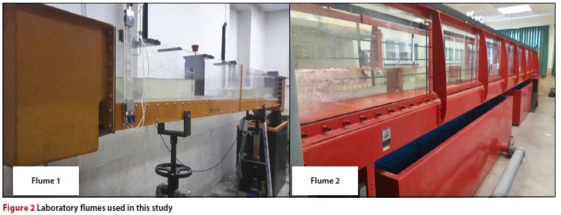
The data used in this research was obtained from experiments performed on two hydraulic laboratory flumes in the Water Sciences and Engineering Department of Arak University. These two laboratory flumes are 2q cm and 5q cm wide, respectively, and are shown in Figure 2.
The experimental conditions are shown in Table 1 (Flume 1 and Flume 2). In addition, in order to increase the range of Froude numbers, USBR data was used (Peterka 1984). For this purpose, 89 data sets were extracted as A, B, C, D and E flumes (Table 1).
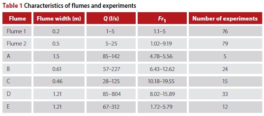
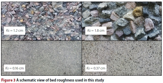
In this study, an ultrasonic flow meter with a precision of ±0.5% was used to measure the flow discharge. In order to form a hydraulic jump, the flow in various discharges and different depths was passed through a radial gate. Then the hydraulic jump was formed by adjusting the weir installed downstream of the flume to create a suitable sequent depth. Finally, the depths before and after the hydraulic jump were measured by a point gauge. Five bed surfaces were tested in the experiments: smooth bed, ks= 0.16, 0.37, 1.2 and 1.8 cm. Figure 3 shows the bed roughness used in these experiments.
For estimating the average error of the model, Equation 7 is used as follows:
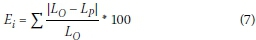
Where: Ei is the percentage of errors, and Lo and Lp are respectively the observed and computed values of L/y1-
RESULTS AND DISCUSSION
Dimensional analysis
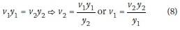
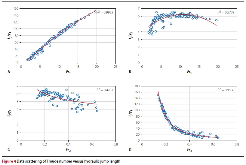
Equation 6 is considered for dimensional analysis. According to the continuity equation (Equation 8), there is a definite relationship between V1 and v2. Therefore, one of the velocities can be eliminated from Equation 6. If v2remains, the final equation is obtained in terms of Fr2. Also, if V1 remains, the final equation is obtained in terms of Fr1-
To eliminate v1or v2in the final equation, four types of graphs are drawn (Figure 4). As shown in Figure 4, for Graph A the regression coefficient is more than 99% and the data scattering is appropriate. Also, the regression coefficients in Graph B (like USBR graph), Graph C and Graph D are 57%, 47% and 95% respectively.
According to Figure 4, the best fitness is observed for Graph A, where L/y1is placed versus Frr So, L/y-y1versus Fr1can be used to determine the new model, and v2will be eliminated from Equation 6. Therefore, by the elimination of v2, Equation 6 can be written as follows:
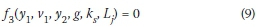
According to Equation 9 and the Buckingham theorem, there are four dimensionless parameters, defined as:
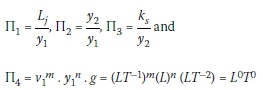
By solving the system of equations, one can write the following relationship:
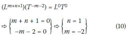
By determining the unknown parameters, the fourth dimensionless parameter will be equal to:
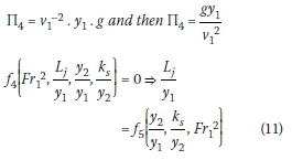
Since the ratio of y2/y1 is a function of Frithis parameter can be ignored in the dimensional analysis and Equation 11 can be written as:
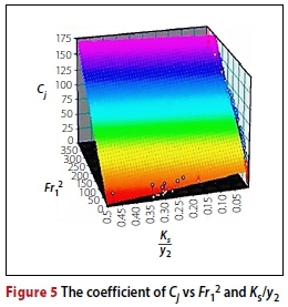
The coefficient Cj was determined using 3D Table Curve software and experimental data. The three-dimensional version of this software was used to determine regression equations; therefore, by considering the Fr12in the x-axis, Ks/y2in the y-axis and the measured values of Cj in the z-axis values, the best fitted curve equation is determined. Figure 5 shows the diagram for data fitting in the Table Curve software.
The selected equation for fitted surface is as follows:
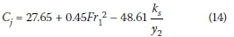
As can be seen, the accuracy of the determined coefficient provided by the software is more than 89% and the standard error is less than 12%.
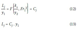
By replacing Equation 14 by the coefficient Cj in Equation 13, the hydraulic jump length can be achieved. Therefore, the final equation for determining the hydraulic jump length is as follows:
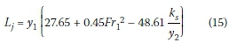
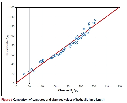
Equation 15 shows that the hydraulic jump length is a function of the roughness and hydraulic conditions before and after the jump. A total of 80 data sets were used for verification of the model. To do this, the observed hydraulic jump length was considered in the horizontal axis, and the jump length computed by Equation 15 was transferred to the vertical axis. As can be seen in Figure 6, the results are close to the identity line (y = x). Also, according to Equation 7, the percentage error obtained was equal to 8%.
CONCLUSION
Roughness is one of the most effective factors in hydraulic jump length. With increasing roughness in the stilling basin, the flow resistance and energy dissipation increase. Therefore, the jump length will change. The main purpose of this research was to develop a model for hydraulic jump length considering the roughness effect. First of all, the momentum equation was used to determine the effective parameters on hydraulic jump length. Then, by measuring the dimensional analysis and Buckingham theorem, the hydraulic jump length model was determined with a coefficient. This coefficient is a function of bed roughness, secondary depth, and Froude number. To determine this coefficient, Table Curve software and experimental data were used. The experimental data included two data series obtained in this study and a series of data from USBR experiments.
USBR data was used to increase the range of the Froude number. The best equation was achieved in terms of simplicity of equation, with high regression and low standard error using Table Curve 3-D software. After that, in order to estimate the percentage error of the model, the computed values of jump length were compared with the observed values. Comparison of the computed values of jump length by the new model with the observed values, shows that the model percentage error is very low. Therefore, this model can be used to design a stilling basin, considering the bed roughness.
REFERENCES
Alikhani, A, Behroozi-Rad, R & Fathi Moghadam, M 2010. Hydraulic jump in stilling basin with vertical end sill. Journal of Physical Sciences, 5(1): 25-29. [ Links ]
Chanson, H 2009. Current knowledge in hydraulic jumps and related phenomena. A survey of experimental results. European Journal of Mechanics, B/Fluids, 28: 191-210. [ Links ]
Ead, S A & Rajaratnam, N 2002. Hydraulic jumps on corrugated beds. Journal ofHydraulic Engineering, 128(7): 656-663. [ Links ]
Hager, W H & Bremen, R 1989. Classical hydraulic jump: Sequent depth. Journal of Hydraulic Research, 27(5): 565-585. [ Links ]
Imran, H M & Akib, S 2013. A review of hydraulic jump properties in different channel bed conditions. Life Science Journal, 10(2): 126-130. [ Links ]
Izadjoo, F & Shafai Bejestan, M 2007. Corrugated bed hydraulic jump stilling basin. Journal of Applied Sciences, 7(8): 1164-1169. [ Links ]
Jain, S C 2001. Open-channel Flow. New York: Wiley. [ Links ]
Kumar, M & Lodhi, A S 2016. Hydraulic jump over sloping rough floors. ISHJournal of Hydraulic Engineering, 22(2): 127-134. [ Links ]
Nasr Esfahani, M J & Shafaei Bajestan, M 2012. Effect of roughness height on the length of B-jump at an abrupt drop. International Research Journal of Applied and Basic Sciences, 3(S): 2757-2762. [ Links ]
Pagliara, S, Lotti, I & Palermo, M 2008. Hydraulic jump on rough bed of stream rehabilitation structures. Journal of Hydro-environment Research, 2(1): 29-38. [ Links ]
Peterka, A J 1984. Hydraulic design of stilling basins and energy dissipators. Monograph No. 25 Denver, CO: United States Bureau of Reclamation (USBR). [ Links ]
Riazi, R & Jafari, S 2014. The characteristics of submerged hydraulic jump in sloped stilling basins with rough bed. Bulletin of Environment, Pharmacology and Life Sciences, 3(6): 238-243. [ Links ]
 Correspondence:
MRS FATEMEH YOUSEFI
Water Science and Engineering Department
Arak University
Shariati Square
Arak
Iran 38156-879
E: shima_20_10_67@yahoo.com
DR JAVAD MOZAFFARI
Water Science and Engineering Department
Arak University
Shariati Square
Arak
Iran 38156-879
E: javad_370@yahoo.com
DR SEYED ASADOLLAH MOHSENI MOVAHED
Water Science and Engineering Department
Arak University
Shariati Square
Arak
Iran 38156-879
E: movahed244@yahoo.com

MRS FATEMEH YOUSEFI is an MSc student of irrigation and drainage at Arak University. Her thesis on hydraulic jump on rough beds forms the basis of the research presented in this paper.

DR JAVAD MOZAFFARI is Assistant Professor of water structures at Arak University since 2010. The research for his PhD thesis, which was carried out at EPFL University, Lausanne, and completed at Tehran University in 2009, was based on river flow patterns. Presently, his research focus is on river hydraulics and river pollution.

DR SEYED ASADOLLAH MOHSENI MOVAHED obtained his PhD in water science and engineering from Tarbiat Modares University in Tehran. His thesis was about optimising the hydraulic performance of water distribution channels. Other areas of his research include hydraulic models, the study of the jump phenomenon on rough surfaces and surface irrigation hydraulics.

