


Services on Demand
Article
 English (pdf)
 Article in xml format
 Article references
Indicators

Related links
-
 Cited by Google
 -
 Similars in Google
Share

 Permalink
Journal of the South African Institution of Civil Engineering
On-line version ISSN 2309-8775
Print version ISSN 1021-2019
J. S. Afr. Inst. Civ. Eng. vol.61 n.1 Midrand Mar. 2019
http://dx.doi.org/10.17159/2309-8775/2019/v61n1a5
TECHNICAL PAPER
The application of restructuring of knowledge in civil engineering
T Verbeek; T J D Bothma
ABSTRACT
In this paper, it is shown how knowledge theories and knowledge acquisition techniques are integrated by contextualisation to lead to the drawing of concept maps that can be used in civil engineering design, and to analyse and record specific experience. The concept maps form part of concept-based ontologies that are analysed to identify problems and constraints. Solutions to these problems and constraints create new knowledge and can be reported and linked to the world-wide-web. This linkage is made possible by utilising the Top-Level-Ontologies or Upper-Level-Ontologies to link to existing or new ontologies on the world-wide-web. The logic base acts as a procedure to lead and integrate all the above-mentioned aspects into three modules. These modules of the logic base are described and simple examples are given of how the logic base functions. The logic base is a technique to bring knowledge closer to the practising engineer, and facilitates thinking processes that will greatly assist in systematising knowledge, the analysis thereof and making it accessible on the word-wide-web.
Keywords: logic base, ontology, concept diagrams, concept maps, knowledge representation, case studies
INTRODUCTION
The word-wide-web and numerous publications offer virtually unlimited scope for obtaining information on engineering matters. Engineers, having to work in a world of increasing complexity, find it almost impossible to access, analyse and study vast amounts of complex information. This situation is exacerbated by a shortage of experienced engineers (Elliott 2017; Lawless 2005; Department of Higher Education and Training 2014). A dichotomy, therefore, exists between the knowledge sources and the demands for knowledge by practising civil engineers. In order to address this dichotomy, extensive research was carried out to find ways of addressing this problem (Verbeek 2018). Resulting from this research, knowledge restructuring is done. The applications of restructuring knowledge are discussed in this paper, whilst the theoretical aspects are discussed in Verbeek and Bothma (2018). The restructuring is done by adopting knowledge theories and repackaging knowledge into ontologies. Ontologies represent categories of concepts, their properties, the values of the properties, events and their causes and effects, processes and time (Gasevic et al 2009). Concept maps are used to represent and analyse knowledge. The restructuring of knowledge is done by using what is called a "logic base" to represent a model to guide and integrate various knowledge restructuring processes. The goals of restructuring knowledge are to make knowledge explicit, to analyse and enhance knowledge, to structure knowledge into ontologies and to facilitate linkage and interoperability of knowledge structures with other ontologies on the world-wide-web. In this paper, applications of the logic base are discussed by first considering a very brief overview of the theory of the restructuring process and then to look at a few examples.
The application of the logic base is based on a civil engineering environment, but may also apply to other engineering fields. The point of departure of the restructuring discussed in this paper is to consider any matter or case that is placed in focus by the engineer to deal with. The architecture and operation of the logic base are described in the sections to follow.
THE ARCHITECTURE OF THE LOGIC BASE
The knowledge base integrates, in a single model, the processes relating to knowledge theories, knowledge acquisition, concept maps, relationship analysis and reporting. The complete architecture of the logic base is shown in Figure 1 and is referred to in subsequent sections.
Figure 1 shows that the logic base has three modules (or functional units), namely, modules A, B and C, being the input, analysis and output modules respectively.
Module A (the input module) is divided into four sub-modules, namely, Module A1 that covers the theories of knowledge, Module A2 that deals with knowledge acquisition, Module A3 that discusses contextualisation, and Module A4 that covers concept maps. Each sub-module is discussed in the sections to follow.
MODULE A
Module A1: Knowledge theories
This first module of the logic base contains fundamental theories of knowledge on which the logic base is built. These theories show the thinking required to enable the restructuring of knowledge. In Table 1, a summary is given of these theories.
In summary, knowledge is founded on the theories of cognition. It is also necessary to understand what knowledge is, how knowledge can be classified and how knowledge is made explicit. Sense-making provides the necessary tools for handling complex situations and identifying knowledge and relationships. These theories assist in widening the user's approach to enhance knowledge and to convert tacit knowledge (that functions in the unconscious domain in a person's mind) to explicit knowledge (that is systematically organised or arranged, i.e. coded to be easily communicated and shared) so that knowledge can be reused. Knowledge acquisition is dealt with in the following sub-module.
Module A2: Knowledge acquisition
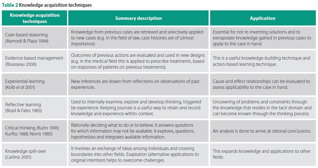
The term knowledge acquisition, as used in this paper, represents "internal" processes in the human mind. It does not necessarily mean to acquire knowledge from external sources. The user reflects on other cases, looks at the evidence and own experiences. In this way, a user can relate more effectively to the case in hand and find solutions to problems and challenges. A selection of knowledge acquisition techniques is shown in Table 2.
The knowledge acquisition techniques in Table 2 can be summarised as follows:
■ Comparisons are made of the matter or case in hand with previous cases or actions (prior knowledge). The similarities invoke previous reasoning processes, and inferences are drawn. These processes add to a person's knowledge.
■ Rationalisation takes place where a person examines, explores and integrates information to come to a belief. The above techniques guide the user to identify, dissect, review and sort knowledge (referred to as "knowledge units") to enable contextualisation of knowledge at hand. It contributes to the search of solutions to problems and constraints.
A systems approach is fundamental to the handling of cases to be studied, and also for the restructuring of knowledge (Blanchard & Blyler 2016; Haines 1998). The theories of knowledge and of knowledge acquisition are part of a system approach and need to be placed in that context. These are dealt with in the following section.
Module A3: Contextualisation
Knowledge acquisition deals with the way people think and how they understand the cases/matters under consideration. However, the foregoing needs to be rationalised and put into practice by doing the following:
■ Examine a case and identify as many uncertainties as possible.
■ Identify the significant external influences on the system under consideration.
■ Identify the various phases (past, current and future, as well as development phases, such as conceptual, feasibility, detailed design, implementation, operations and retirement phases).
■ Identify the main issues to explore.
The above process provides context to the case in hand and is termed contextualisation.
The processing of knowledge is depicted by the knowledge processing framework in Figure 2.
Once the contextualisation is done, the next step in the restructuring of knowledge is the drawing of concept maps. This is shown in the following section.
Module A4: Concept maps
Concept maps are graphical representations of cognitive processes in the human mind (Borst 1997). The concepts are drawn in boxes and connected with lines or arrows, indicating some kind of relationship between them. There is a hierarchy in the concepts, denoted by various ontological levels which will be shown in further sections.
Once a concept map has been drawn, the relationships between the concepts are analysed by the application of problemsolving techniques (Gruber 1993; Novak and Canas 2008; Verbeek 2018).
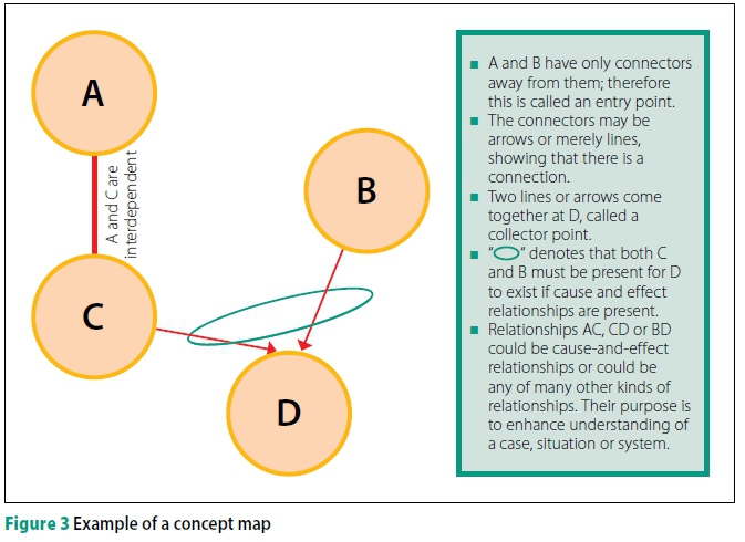
A concept map is illustrated in Figure 3.
The concepts are denoted by A, B, C and D in Figure 3. These concepts could be the following:
■ Concept A: The formwork for the bridge deck must be checked and signed off.
■ Concept C: The rebar in the bridge deck must be checked and ready.
■ Concept B: The trucks that transport the ready-mixed concrete must be ready (including all the logistics).
■ Concept D: The process of concreting the bridge deck.
The relationships indicate that both the rebar and the trucks that transport the ready-mixed concrete (and the associated logistics) must be in place to do and complete a concrete pour.
The relationships between the various concepts can be analysed to get to a full understanding of the system's operation. This is discussed in subsequent sections.
Module A4: Ontologies
The linking of knowledge (i.e. the outputs from the logic base) to the world-wide-web, necessitates arranging the knowledge into ontological structures. Ontologies are similar to taxonomies where entities are classified according to strict hierarchical protocols (Cebrian-Tarrason & Vidal 2008; Noy & McGuinness 2001). Ontologies have a wider content and additional characteristics to those of taxonomies (Verbeek 2018).
The basic ontological structure
In research conducted (Verbeek 2018), it was found that the typical topics found in the reporting of a variety of case studies regarding engineering issues are the most appropriate basis for defining ontologies. The following topics are typically found in case studies involving engineering issues and are derived from the format found in a large number of case studies (Delatte 2009; Jones 1998; Jones 2001; LePartner & Johnson 1982).
■ Introduction and scope
■ Design
■ Construction/manufacturing
■ Operations and maintenance
■ Setting and context/narrative/role players and relationships/real examples
■ Sequence of events and causal path
■ Investigation, problems, constraints and issues
■ Interpret actions, solutions and actions taken
■ Technical, legal and ethical lessons learned
■ Educational aspects, extrapolation and replication
■ References
■ Influencing domain (which includes variables such as time, pace and resource capacity).
Various levels of ontologies are defined as follows:
Top-Level Ontology (TLO)
This is the foundational ontology and is also linkable to other ontologies on a world-wide-web. (This linkage might have to be via the introduction of several links to suit the external ontology.) The TLO is made up of concepts derived from the typical topics found in case studies. The topics of case studies represent a logical grouping of concepts and cover most reported case studies in industry. Furthermore, when considering the approach to engineering matters, these can be restructured by categorisation in one or many TLO concepts.
The concept map for the Top-Level-Ontology (TLO) is shown in Figure 4.
High-Level Ontologies (HLO)
For every concept in the TLO, a breakdown of concepts can be done and these are grouped into different HLOs. This breakdown of concepts in the HLOs provides a series of concepts put together to support various aspects in a civil engineering environment. An example of an HLO is shown in Figure 5.
Upper-Level Ontologies (ULO)
The ULO is an ontology made up of selected concepts from the HLOs and is used for customisation to meet user requirements. A ULO has exactly the same hierarchical status as the constituent HLOs. It should be noted that the concepts in this HLO may be defined to suit the user requirements and could be rather flexible. It is only with the Top-Level Ontology (TLO) that one would prefer to keep the concepts the same to enable easier linkage to a web environment.
Case-Specific Ontology (CSO)
The CSO is defined by a user and has its own selection of concepts. A unique concept map can be drawn to represent a specific case study or any specific civil engineering matter under consideration. An example could be when considering earthworks construction. When such a specific case is analysed, it is the easiest to first draw a CSO to represent the case (doing earthworks). By then referring to the HLOs or the appropriate ULO, the gaps between the CSO and the HLO (or ULO) can be identified. The HLOs can act as checklists to ensure complete treatment. It is important to link the CSO to the appropriate HLOs from where they link to the TLO, and therefore also to the world-wide-web. An example of a simple CSO relating to earthworks is shown in Figure 6.
Technical Ontology (TO)
Engineering cases often have a discipline-analytical content and concept statements contain discipline-specific content.
Relationships between technical parameters or concepts are studied and these "technical" relationships are mostly computational of nature. However, in civil engineering, relationships are not necessarily computational. A technical ontology is designed to cater for the quantitative and qualitative requirements. The ontology has two parts, namely a TO that links to the CSO and to a Functional Analysis (FA) component. A TO contains qualitative concepts that link to a specific FA. There could therefore be several TOs, each linking to a particular FA. The TOs then link to a CSO. All the parameters that may be involved in achieving a specific goal or function are taken into account and analysed in the FA (Mann 2009; Scheinkopf 1999; Suh 2001).
Functional Analysis (FA)
An FA entails listing of all the parameters that may contribute to particular functions. First of all, the Main Useful Function (MUF) or ultimate goal of the system must be defined. In order to achieve the MUF, sub-requirements (or specifications) termed the Upper-Level Functional Requirements (ULFR), must be satisfied. To satisfy a ULFR, there could be a large number of parameters that contribute to the end result of the ULFR. The Lower-Level Functional Requirements (LLFRs) are all the contributing parameters that cumulate to determine the value of the ULFR. The LLFRs can be qualitatively or quantitatively interrelated. In quantitative relationships, the LLFRs are variables in equations of which the ULFR is the dependent variable. The FA accommodates the parameters (which are also concepts) to enable analysis. This is best illustrated by way of an example in Table 3 where a functional analysis matrix and an example are shown.
The ULFRs are shown in the columns, and the rows of the matrix show the LLFRs. In the example there are two ULFRs, namely discharge volume and the limitation on the width of the canal. The main contributory parameters are the LLFRs, Manning's roughness coefficient "κ-value" (LLFR1). The second is the ratio between the area and the wetted perimeter, constituting LLFR2. The third is the slope of the canal, LLFR3. The matrix shows which LLFRs participate to yield the desired ULFR. There are mathematical/empirical relationships that would determine the value of the attributes. In order to satisfy the MUF, both the ULFRs must be met.
The potential impact of the area development plan is not listed in the table, but it will have to appear in the TO where there could be a specific concept, named "Future developments". In the HLOs, time, space and capacity have to be superimposed in all the analyses and will be captured in the influencing domain in the TLO. This "future development" concept has a direct relationship with the ULFRs and its LLFRs. (The slope, roughness and infiltration can all be influenced by aspects of the future developments.) In this way, a systematic analysis can be done to arrive at the problems, constraints and outputs from the analysis. The FA serves as an excellent source of knowledge and record of experience.
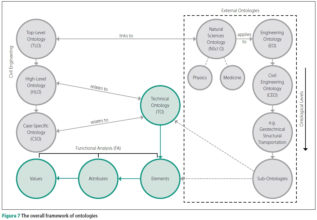
The overall structure of ontologies is shown in Figure 7. The figure shows where each level of ontology fits into the total framework. On the right-hand side of Figure 7, the linkage to external ontologies is shown. It also illustrates how one can start an ontology in a hierarchical way with the natural sciences, followed by engineering, civil engineering and then discipline-specific ontologies such as structures, geotechnical, roads, transportation, water resources, hydrology and other civil engineering disciplines.
The purpose of the ontologies is to create a functional structure (restructuring of knowledge from original word-descriptions to concept maps and ontologies) for analysis and reporting. The next module is the analysis module, Module B, which is discussed in the following section.
MODULE B - ANALYSIS
In this analysis module, knowledge creation takes place through the application of problem-solving techniques. A selection of appropriate problem-solving techniques are summarised in Table 4.
Summarising from Table 4, various problem-solving techniques can be classified as follows (Verbeek 2018):

The second module, Module B, represents the analysis part where relationships are studied, and contradictions and constraints are identified. A useful way to study relationships is to compile a Concept Matrix (CM) to identify all the possible relationships. The effects of all the concepts on one another and the effects of factors in the influencing domain on each relationship can be studied. All the concepts are listed in a spreadsheet. Pairing the concepts in each row and column with one another, ensures that all the possible relationships are noted and considered. When a problematic relationship is discovered, that relationship can be given a particular reference number to a description and analysis of the problem. All the outcomes of the previous modules are reported in Module C.
MODULE C - OUTPUT MODULE
In this module, the outcomes of the preceding sections are reported and discussed.
The reporting format in Module C is as indicated in Table 5.
Table 5 shows that the various ontology levels are used to lead to the case knowledge and vice versa.
Example: Structural beam
In order to illustrate the foregoing, consider an example of the strength design of a simply supported steel beam, spanning between two supports, bolted into position. (Serviceability considerations can also be included.) Table 6 applies.
Module A1
The comments on the RHS column represent important issues that should all be determined and decided at the beginning of the project.
The next module considers knowledge acquisition.
Module A2
In this module, the various knowledge acquisition techniques are considered. Table 7 applies.
The above knowledge acquisition techniques can be applied throughout the design process and are part of knowledge enhancement. The next module consolidates the knowledge in hand by contextualisation.
Module A3
This contextualisation is done from the preceding knowledge theories and the knowledge acquisition techniques as described in the previous section. Table 8 applies.
The above contextualisation shows the relationships between the knowledge theories and knowledge acquisition techniques and how contextualisation is done. The concept maps can now be drawn.
Module 4: Concept maps
From the contextualisation, the CSO (Case-Specific Ontology) map for the design of the steel beam can be drawn. A TO (Technical Ontology) can also be drawn to accommodate specific concepts related to the FA (Functional Analysis).
The main concepts are as follows (also see Figure 8):
■ MUF (Main Useful Function). Structural support (first concept).
■ Effective span. (This will depend on the chosen steel section, other connections to the beam, and the end conditions or fixation.)
■ Loading conditions. (This is specified by the owner. However, uncertainties are often encountered with loading conditions that often change over time.)
■ Supports and fixation - including lateral support. (These conditions need to be understood, including requirements for installation (constructability) and possible effects of fatigue due to cyclic loading.)
■ Beam type, dimensions and configuration. (The floor clearances need to be taken into account.)
The concept map in Figure 8 reflects the main concepts for the design of the steel beam. (This is for illustration purposes only. In practice, both ultimate and serviceability limit states would have to be considered). The next part is the analysis part, Module B.
The concept map illustrates that both the span and the loading conditions are crucial performance characteristics or "demands" constituting the MUF (Main Useful Function) of the beam. The question is: how can these demands or ULFRs (Upper-Level Functional Requirements) be met? The answer lies in the definition of the LLFRs (Lower-Level Functional Requirements) pertaining to each ULFR.
For the ULFR "Span", the clear span between the supports is fixed in this example.
The ULFR for "Loading" is determined by the serviceability limits criteria represented by the stress conditions in the steel when loads are applied. The stress conditions in the beam will be determined by a number of parameters (LLFRs), as indicated in Table 9, the FAM.
The relationships between the ULFR and every LLFR can be calculated or determined from empirical relationships. The results of the calculations can be stored in calculation sheets as reference documents attached to the logic base. The relationships can also be studied by using a CM (Concept Matrix), as shown in Table 10.
Only six relationships, as denoted by the numbers in Table 10 (the X symbols denote complementary relationships that are already numbered) are possible and can be determined by equations or empirical relationships applicable to the discipline of structural engineering.
There are other factors that play important roles in the LLFRs, such as the following:
■ Micro-climate conditions
■ Corrosion intensity and types
■ Availability of steel sections
■ Uncertainties concerning the loading conditions (this is often a rather problematic issue in industrial plants).
The above factors can influence the design. These factors are more of a qualitative nature and form concepts in the TO or the CSO, if appropriate.
Module C: Output of the logic base
The outputs of the logic base are summarised in Table 11.
Output protocols
An output protocol is defined as a suggested rule for practitioners to follow. It emanates from the analysis of cases and is put forward as general rules to follow, not limited to only the case study under consideration. The protocols should form part of the industry knowledge base for every practitioner to take careful note of.
Example: Mechanically Stabilised Earth (MSE)
This descriptive study informs readers of the method of functioning of Mechanically Stabilised Earth (MSE) and describes the applications and advantage of this method (Smith 2013).
Module A: Synopsis/narrative
This method was invented in 1957 by Henri Vidal, a French architect and engineer, whilst playing with pine needles and beach sand (Smith 2013). The method involves stabilising an earth embankment by means of tieback strips inserted during the construction of an earth fill. Typically, flat metal strips are inserted perpendicularly to a vertical face of an earth fill. The metal strips are then tied to a facing material for the retention of earth on the vertical face of an embankment. This method of building stable-fill embankments has become popular and is used throughout the world. These fill embankments can be used successfully for the support of bridge decks. The sketch in Figure 9 illustrates a cross-section of the layout.
The layout shows how reinforcing strips are placed in a soil embankment during construction to reinforce the earth, thereby permitting a vertical face on the traffic side of the abutment. The Case-Specific Ontology (CSO) concept map is shown in Figure 10.
The CSO concept map in Figure 10 shows the main concepts of construction of an embankment by using Mechanically Stabilised Earth (MSE). The next step is to map the CSO with the generic HLO. This is described in the paragraphs below.
Module B: Analysis
Note: Only some examples of HLOs are presented in this paper. For more comprehensive details, refer to Verbeek (2018).
The first five paragraph headings below represent concepts belonging to HLOs.
Purpose
The purpose of this method is to create a stable embankment, on which infrastructure can be constructed.
■ Construction must be possible in poor founding conditions.
■ The structure (both the abutment and the bridge) must not be sensitive to settlements.
■ The construction duration must be as short as possible.
■ There must be a smooth transition between the earth approaches and the concrete deck.
Configuration
In this method, horizontal reinforcement is placed in an embankment fill. The reinforcement is placed in alternating layers of compacted soil and soil where reinforcement has been placed. The face(s) of the embankment are typically vertical, and cladding is positively connected to the horizontal reinforcement to provide an aesthetically pleasing façade.
Mechanism of operation
The horizontal reinforcement in the fill restrains lateral strain by friction between the soil and the reinforcing elements in the soil. The effect is the same as if a lateral restraining load is applied to the soil. As the vertical stress is increased, so do lateral stresses increase in direct proportion. The horizontal strain in the earth is restrained by the reinforcing elements.
Operational principles
In soil mechanics, the volumetric stressstrain relationship is of importance (this is part of the TO). If a vertical stress is applied to a soil specimen, horizontal stresses increase in direct proportion (and vice versa). However, due to the behaviour of particulate media, such as compacted soil, a small lateral force or restraint would have a larger proportional effect on the vertical load-bearing capacity. (This is illustrated and can be calculated with reference to the Mohr-Coulomb failure criteria (Das & Sobhan 2014)).
Influencing domains
Geotechnical considerations
■ Geochemical environment
■ Construction quality control and assurance
■ Seismic events
Relationships and possible failure mechanisms (combining it with problem-solving techniques)
Relationships are stated and evaluated according to the TRIZ method (substance-field relationships) (Mann 2009; Gadd 2011). Comments are given on each relationship that can be reported in the output module.
■ Relationship: Embankment and subsoil. Potential failure of foundation soil and potential settlement - both conditions can adversely affect the mechanically stabilised earth embankment.
■ Relationship: Soil and compaction equipment. It might not be possible to properly compact poor soil to the required specification.
■ Relationship: Metal or polymer strips and soil. Strips may slip due to insufficient friction between strips and poorly compacted soil.
■ Relationship: Metal or polymer strips and moisture in soil. The frictional resistance between the metal or polymer strips and the soil can reduce due to a reduction of effective stress as a result of excess pore pressure (a phreatic surface may form in the fill). Moisture could also, through the transportation of ions, cause corrosion that could destroy the metal strips.
■ Relationship: The extensivity of the metal or polymer strips and the lateral strain in abutment fill. Extension of strips such that lateral forces cannot be mobilised.
■ Relationship: Metal or polymer strips and facing material connections. Possible failure of metal connections at the cladded face due to poor design/ manufacturing or due to corrosion on soil/air interface.
■ Relationship: Bridge foundation and soil embankment. Soil in MSE may settle and cause excessive settlement of bridge.
■ Relationship: Rainfall and embankment. Rain can dam up on the embankment and saturate the soil, weakening the soil structure as a result of excessive pore pressure (phreatic surface may form). Insufficient drainage of fill, as well as surroundings, can result in failure of the embankment.
The above set of relationships are deduced from the case study and are not directly reported in the script of the study.
Technical Ontology (TO)
The functioning of the metal strips relative to the soil can be expanded in a Technical Ontology (TO). For example, the shear resistance of the strips can be considered. There is a functional relationship between the soil properties and the vertical-effective stress and the shear that can develop between the soil at particular points along the strips. The relationships can be determined by laboratory testing. There are also other important relationships that may need further elaboration. These are conceptually shown in Table 12. Each FR (Functional Relationship) represents a concept statement that can be further expanded in a TO.
The FAM (Functional Analysis Matrix) can also be compiled to extend the analysis as shown in Table 12, in a slightly different format than previously. (The relationships are sequentially numbered.)
Each individual cell should have a reference number, as indicated in Table 12. Each relationship can be referenced, listed, described and analysed. For example, relationship 1 denotes the relationship between soil type and settlement. In this case, the clay content, type of clay, thickness of the clay, stress history and changes in stress conditions in the clay are important considerations. The perceived important relationships are marked with bold numbers. These may need special attention by way of, for example, laboratory analysis of the interface of the reinforcing material with the compacted soil. A database with typical friction values may be of great assistance in this regard and can be linked to this item in the logic base (for example through the H.O.T. technique).
This case study is, in fact, a descriptive study and does not present specific experience or convey knowledge other than introducing the technicalities of employing mechanically reinforced earth for use in bridge abutments.
Module C: Reporting
Reporting in the logic base is done as in Table 13.
CONCLUSIONS
In this paper, it is shown how knowledge theories and knowledge acquisition techniques are integrated by contextualisation to lead to the drawing of concept maps that can be used in civil engineering design and to analyse and record specific experience. The concept maps form part of concept-based ontologies that are analysed to identify problems and constraints. Solutions to these problems and constraints create new knowledge and can be reported and linked to the world-wide-web. This linkage is made possible by utilising Top-Level-Ontologies or Upper-Level Ontologies to link to existing or new ontologies on the world-wide-web. The logic base acts as a procedure to lead and integrate all the above-mentioned aspects into three modules. These modules of the logic base were described and simple examples were given of how the logic base functions. The end result in Module C (output module) contains all the outcomes of the processes and can provide valuable knowledge. In essence, the original words and descriptions of a case or matter under consideration are restructured into ontologies, and analysis is done. This enhances knowledge and makes it, in a succinct way, more readily available for reuse.
The logic base is a technique to bring knowledge closer to the practising engineer and facilitates thinking processes that will greatly assist in systematising knowledge, the analysis thereof and making it accessible on the word-wide-web.
REFERENCES
Aamodt, A & Plaza, E 1994. Case-based reasoning: Foundational issues, methodological variations and system approaches. AI Communications, 7(1): 39-59. [ Links ]
Bartolomei, J E & Miller, T 2001. Functional Systems Analysis Technique (F.A.S.T.) as a group knowledge elicitation method for model building. Proceedings, 19th International Conference of the System Dynamics Society, Atlanta, GE. Available at: http://www.systemdynamics.org/conferences/2001/papers/Bartolomei_2.pdf[accessed on 14 August 2017]. [ Links ]
Blanchard, B S & Blyler, J E 2016. Systems Engineering Management, 5th ed. Hoboken, NJ: Wiley. [ Links ]
Borst, W N 1997. Construction of engineering ontologies for knowledge sharing and reuse. PhD Thesis, Enschede, the Netherlands: University of Twente. [ Links ]
Boyd, E M & Fales, A W 1983. Reflective learning: Key to learning from experience. Humanistic Psychology, 23(2): 99-117. [ Links ]
Browning, L & Boudès, T 2005. The use of narrative to understand and respond to complexity: A comparative analysis of the Cynefin and Weickian models. Emergence: Complexity and Organization, 7(3-4): 32-39. Available at: http://www.old.cognitive-edge.com/wp-content/uploads/2005/01/51-Browning-Boudes-on-Weick-and-Snowden.pdf[accessed on 14 August 2017]. [ Links ]
Carlino, G A 2001. Knowledge spillovers: Cities' role in the new economy. Business Review Quarterly, 4: 17-24. [ Links ]
Cebrian-Tarrason, D & Vidal, R 2008. How an ontology can infer knowledge to be used in product conceptual design. In: Cascini, G (Ed.). Proceedings, IFIP 20th World Computer Congress, Computer-Aided Innovation (CAI), 7-10 September, Milan, Italy. Boston, MA: International Federation for Information Processing, pp 57-68. [ Links ]
Das, B M & Sobhan, K 2014. Principles of Geotechnical Engineering, 8th ed. Stamford, CT: Cengage Learning. [ Links ]
Delatte, N J 2009. Beyond Failure: Forensic Case Studies for Civil Engineers. Reston, FL: ASCE Press. [ Links ]
Department of Higher Education and Training 2014. National scarce skills list: Top 100 occupations in demand: Comments invited. Government Gazette 37678, 23 May (Regulation Gazette No. 37678). Available at: http://www.gov.za/documents/national-scarce-skills-list-top-100-occupations-demand-comments-invited[accessed on 15 August 2017]. [ Links ]
Elliott, C 2017. Five sought-after engineering skill sets for 2017 and beyond. E&T Engineering and Technology. Available at: https://eandt.theiet.org/content/articles/2017/01/five-sought-after-engineering-skill-sets-for-2017-and-beyond/ [accessed on 3 January 2018]. [ Links ]
Gadd, K 2011. TRIZ for Engineers - Enabling Inventive Problem Solving. Hoboken, NJ: Wiley. [ Links ]
GaseviC, D, Djuric, D & Devedzic, V 2009. Model Driven Engineering and Ontology Development, 2nd ed. Dordrecht, Germany: Springer. [ Links ]
Gick, M L & Holyoak, K J 1980. Analogical problem solving. Cognitive Psychology, 12(3): 306-355. [ Links ]
Govindaraju, M & Mital, A 2008. Design and manufacture of usable consumer products. Part I. Review of the literature. Integrated Manufacturing Systems, 12(6): 430-448. [ Links ]
Grönqvist, M, Male, S & Kelly, J 2006. The Function Priority Matrix - Meeting the function of function analysis. Value Solutions©. Available at: http://www.citeseerx.ist.psu.edu/viewdoc/download?doi=10.1.1.514.1667&rep=rep1&type=pdf[accessed on 30 January 2011]. [ Links ]
Gruber, T R 1993. A translation approach to portable ontology specifications. Knowledge Acquisition, 5(2): 199-220. [ Links ]
Haines, S G 1998. The Manager's Pocket Guide to Systems Thinking and Learning. Amherst, MA: HRD Press. [ Links ]
Harsh, O K 2009. Three-dimensional knowledge management and explicit knowledge reuse. Journal of Knowledge Management Practice, 10(2): 1-10. [ Links ]
Hugo, F 1991. Draft South African road constructability guide. South African Roads Board Research and Development Advisory Committee, Project Report PR 89/062/2. University of Stellenbosch. [ Links ]
Jones, D R H 1998. Failure Analysis Case Studies: A Sourcebook of Case Studies Selected from the Pages of Engineering Failure Analysis 1994-1996. Amsterdam: Elsevier. [ Links ]
Jones, D R H 2001. Failure Analysis Case Studies II: A Sourcebook of Case Studies Selected from the Pages of Engineering Failure Analysis 1997-1999. Amsterdam: Pergamon Press. [ Links ]
Kardos, G 1993. FAST for Systematic Design, revised version. Ottawa, Canada: Carleton University. (First presented at the International Conference on Engineering Design, August 1988, Budapest, Hungary. [ Links ])
Kellogg, T R 2002. Cognitive Psychology, 2nd ed. London: SAGE. [ Links ]
Kolb, D A, Boyatzis, R E & Mainemelis, C 2001. Experiential learning theory: Previous research and new directions. Perspectives On Thinking, Learning, and Cognitive Styles, 1(8): 227-247. [ Links ]
Kuhn, D 1999. A developmental model of critical thinking. Educational Researcher, 28(2): 16-46. [ Links ]
Kurfiss, J G 1988. Critical thinking: Theory, research, practice, and possibilities. ASHE-ERIC Higher Education Report No. 2, Washington, DC: George Washington University. [ Links ]
Kurtz, C F & Snowden, D J 2003. The new dynamics of strategy: Sense-making in a complex and complicated world. IBM Systems Journal, 42(3): 462-483. [ Links ]
Lawless, A 2005. Numbers & needs - Addressing imbalances in the civil engineering profession. Midrand: SAICE. [ Links ]
LePartner, B B & Johnson, S M 1982. Structural and Foundation Failures: A Casebook for Architects, Engineers and Lawyers. New York: McGraw-Hill. [ Links ]
Luthra, P 1991. FMECA: an integrated approach. Proceedings, IEEE Annual Reliability and Maintainability Symposium, 29-31 January, Orlando, FL, pp 235-241. [ Links ]
Mann, D L 2009. Matrix 2010: Re-updating the Contradiction Matrix. Clevedon, OH: IFR Press. [ Links ]
Nonaka, I 1994. A dynamic theory of organizational knowledge creation. Organization Science, 5(1): 14-37. [ Links ]
Nonaka, I & Takeuchi, H 1995. The Knowledge-Creating Company: How Japanese Companies Create the Dynamics of Innovation. New York: Oxford University Press. [ Links ]
Norris, S P 1985. Synthesis of research on critical thinking. Educational Leadership, 42(8): 40-45. [ Links ]
Novak, J D & Canas, A J 2008. The theory underlying concept maps and how to construct and use them. Technical Report IHMC CmapTools 2006-01 Rev 01-2008, Pensacola, FL: Florida Institute for Human and Machine Cognition. Available at: http://www.eprint.ihmc.us/5/2/TheoryUnderlyingConceptMaps.pdf[accessed on 16 July 2015]. [ Links ]
Noy, N F & McGuinness, D L 2001. Ontology development 101: A guide to creating your first ontology. Stanford Knowledge Systems Laboratory Technical Report KSL-01-05 and Stanford Medical Informatics Technical Report SMI-2001-0880, Stanford, CA: Knowledge Systems Laboratory, Stanford University. Available at: http://liris.cnrs.fr/amille/enseignements/Ecole_Centrale/What%20is%20an%20ontology%20and%20why%20we%20need%20it.htm[accessed on 15 August 2015]. [ Links ]
Polanyi, M 1958. Personal Knowledge: Towards a Post-critical Philosophy. London: Routledge. [ Links ]
Pomerol, J-Ch & Brézillon, P 2001. About some relationships between knowledge and context. Modeling and using Context (CONTEXT-01). Lecture Notes in Computer Science Series, Springer, pp 461-464. [ Links ]
Ritchey, T 1991. Analysis and synthesis: On scientific method - Based on a study by Bernhard Riemann. Systems Research and Behavioral Science, 8(4): 21-41. [ Links ]
Ritchey, T 2002. General morphological analysis. A general method for non-quantified modeling. (Adapted from the paper by Ritchey, T. Fritz Zwicky, Morphology and policy analysis.) Paper presented at the 16th EURO Conference on Operational Analysis, Brussels, 1998. [ Links ]
Rooney, J J & Van den Heuvel, L N V 2004. Root cause analysis for beginners. Quality Progress, 37(7): 45-56. [ Links ]
Rossiter, J R & Lilien, G L 1994. New "brainstorming" principles. Australian Journal of Management, 19(1): 1-13. [ Links ]
Rousseau, D M 2006. Is there such a thing as "evidence-based management"? Academy of Management Review, 31(2): 256-269. [ Links ]
Sarkar, P & Chakrabarti, B 2008. The effect of representation of triggers on design outcomes. Artificial Intelligence for Engineering Design, Analysis and Manufacturing, 22(2): 101-116. [ Links ]
Scheinkopf, L J 1999. Thinking for a change: Putting the TOC thinking processes to use. Boca Raton, FL: St Lucie Press. [ Links ]
Seligmann, R E, Sidorkin, A & Jacobs, M 2007. Reaching students through synectics: A creative solution. EDF500, Educational Foundations and Curriculum Studies. Greeley, CO: University of Northern Colorado. Available at: http://www.ellieseligmann.com/essays/synectics_seligmann.pdf [accessed on 29 Jan 2011]. [ Links ]
Sfard, A 1998. On two metaphors for learning and the dangers of choosing just one. Educational Researcher, 27(2): 4-13. [ Links ]
Silverstein, D, Samuel, P & DeCarlo, N 2012. The Innovator's Toolkit: 50 Techniques for Predictable and Sustainable Organic Growth, 2nd ed. Hoboken, NJ: Wiley. [ Links ]
Smith, A 2013. MSE bridge abutments - a structural solution. Civil Engineering, 21(2): 45-47. [ Links ]
Snowden, D J 2013. Cynefin v 45" complete. Available at: http://www.cognitive-edge.com/blog/cynefin-v45-complete[accessed on 4 September 2015]. [ Links ]
Sternberg, R J (Ed.) 1999. The Nature of Cognition. Cambridge, MA: MIT Press. [ Links ]
Suh, N P 2001. Axiomatic Design Advances and Applications. New York: Oxford University Press. [ Links ]
Verbeek, T 2018. The design of a model for the acquisition, reuse and creation of knowledge in a civil engineering environment. D Phil Thesis. Available at: https://repository.up.ac.za/handle/2263/64301. [ Links ]
Verbeek, T & Bothma T J D 2018. The structuring of knowledge for technology transfer. Submitted for publication to Journal of Technology Transfer. [ Links ]
Wallace, D P 2007. Knowledge Management: Historical and Cross-disciplinary Themes. Westport, CT: Libraries Unlimited. [ Links ]
Youker, R 1998. Defining the hierarchy of project objectives. Linking organizational strategy, programs and projects. Proceedings, 14th World Congress on Project Management, Ljubljana, Slovenia. Available at: http://www.maxwideman.com/guests/hierarchy/example.htm[accessed on 30 January 2011]. [ Links ]
Zack, M H 1999. Managing codified knowledge. Sloan Management Review, 40(4): 45-58. [ Links ]
Zwicky, F 1949. Morphological astronomy. The Observatory, 68(845): 121-143. [ Links ]
 Correspondence:
T Verbeek
1431 Dickenson Avenue Waverley. Pretoria 0186, South Africa
T: +27 83 455 2288 E: tom.vrbk@gmail.com
T J D Bothma
Department of Information Science University of Pretoria
Private Bag X20, Hatfield 0028. South Africa
T: +27 12 420 2293 E: theo.bothma@up.ac.za

DR THOMAS VERBEEK Pr Eng graduated from the University of the Witwatersrand. He obtained a BSc (Hons) in Civil Engineering at the University of Pretoria, an MSc at Stellenbosch University, a BTech in Facilities Management from the Pretoria Technikon (now known as the Tshwane University of Technology), and a Doctorate in Information Science at the University of Pretoria. He worked for BKS Consulting (know part of the AECOM group), and joined Anglo American Kumba Iron, where he held the position of Principal Civil and Structural Engineer. He retired in 2014, but continues to do part-time consulting.

PROF THEO BOTHMA is professor emeritus / contract professor in the Department of Information Science at the University of Pretoria. He is the former Head of Department and Chairperson of the School of Information Technology (until his retirement at the end of June 2016). His research focuses on information organisation and retrieval, knowledge management and web development. He has published widely and presented many papers at local and international conferences. He is joint-editor of Libri, editorial board member of a number of journals, and member of various professional associations.

