


Services on Demand
Article
 English (pdf)
 Article in xml format
 Article references
Indicators

Related links
-
 Cited by Google
 -
 Similars in Google
Share

 Permalink
Journal of the South African Institution of Civil Engineering
On-line version ISSN 2309-8775
Print version ISSN 1021-2019
J. S. Afr. Inst. Civ. Eng. vol.60 n.3 Midrand Sep. 2018
http://dx.doi.org/10.17159/2309-8775/2018/v60n3a5
TECHNICAL PAPER
A numerical investigation on hydro-mechanical behaviour of a high centreline tailings dam
M Naeini; A Akhtarpour*
ABSTRACT
The high rate of failure in tailings dams reflects the inadequacy of conventional stability and seepage analyses for evaluating their performance, especially during construction. In this article, the hydro-mechanical behaviour of a high centreline tailings dam during staged construction is evaluated by coupled stress-pore pressure analyses. The effects of factors such as foundation permeability, raising rate, anisotropic permeability of slimes and changes in the slope of dykes on the structural response are investigated. In these analyses, a combination of realistic conditions, including saturated-unsaturated seepage of materials, consolidation and loading due to staged construction are simulated using SIGMA/W software. The results of this study indicate that foundation permeability and anisotropic permeability of slimes have a significant influence on development of pore pressure in impoundment, while changing the downstream slope of dykes causes substantial displacements.
Keywords: tailings dam, centreline method, coupled hydro-mechanical analysis, staged construction
INTRODUCTION
Proper disposal of mining waste is one of the biggest concerns of major mines in the world. In many mines (especially in copper and gold mines), more than 99% of the processed materials are turned into residual wastes including tailings (Villavicencio et al 2013), which generally contain a considerable amount of water and environmental pollutants. Therefore safe and sustainable tailings disposal is crucial for protecting water resources and the environment against contamination hazards. One common method of tailings management is the construction of tailings dams (with coarse-grained tailings) in the form of raised embankments with upstream, downstream or centreline designs. The objective of such structures is to ensure sufficient and safe storage of tailings during and after mining operations (Hamade & Mitri 2013). However, failure of two to five tailings dams per year on average (Davies 2002; Bowker & Chambers 2015) shows that conventional seepage and stability analyses may not encompass all the behavioural aspects of these structures. Consequently hydro-mechanical analyses aimed at determining the actual behaviour of tailings dams during staged construction and making sure of their stability and safe operation are of vital (Saad & Mitri 2010a).
Besides the dynamic studies, which are beyond the scope of this paper, the latest numerical studies carried out on tailings dams can be divided into three groups. The first group includes seepage analyses performed with the objective of locating the phreatic surface, managing the water resources or providing inputs for stability analyses. See, for example, the studies of Rykaart et al (2001) and Yuan and Lei (2015). The second group comprises conventional stability analyses that utilise numerical or limit equilibrium methods to determine the safety factor under static and/or pseudo-static conditions. See, for example, the studies by Ozcan et al (2013), Wei et al (2016) and Zhang et al (2016). Owing to the complex behaviour of tailings dams during staged construction, the third group of numerical studies focuses on hydro-mechanical analyses. For example, Psarropoulos and Tsompanakis (2008) studied the behaviour and stability of three upstream, downstream and centreline tailings dams during staged construction, and found that from the stability and displacement perspective, the downstream method has the best and the upstream method has the worst performance, while the centreline method provides intermediate results. Saad and Mitri (2010a) performed transient coupled non-linear analyses on an upstream tailings dam built of oil sand, coal wash and gold tailings in staged construction. This study reported that the highest pore water pressure (PWP) in the impoundment and horizontal displacement in the dam body were observed in the model whose materials had the lowest permeability. It was also reported that total and differential settlement in the embankment dykes must be checked to prevent erosion and overtopping (Saad & Mitri 2010b). Hamade and Mitri (2013) developed a new approach for evaluating the performance of the tailings dam by incorporating its hydro-mechanical behaviour as well as uncertainties in material characteristics. Ormann et al (2013) utilised a fully coupled analysis to place rock dykes at the downstream side of the Aitik tailings dam so that with each raise in elevation the safety factor remained higher than 1.5. In a three-dimensional hydro-mechanical analysis of an upstream tailings dam, Hu et al (2015) reported that, given the tailings permeability variations during the staged construction process, the long-term behaviour of the dam is best determined through coupled analysis.
To the authors' knowledge, most numerical studies of tailing dams have been conducted with the upstream method and/or a height of less than 40-60 m. However, in most countries, such as Chile, the upstream method is forbidden outright (Villavicencio et al 2013), and in large mines where a high volume of tailings needs to be disposed the use of high tailings dams is inevitable. In this article, the coupled hydro-mechanical (stress-pore pressure) behaviour of a high centreline tailings dam is evaluated by coupled stresspore pressure analysis, and the effects of important factors such as foundation permeability, raising rate, anisotropic permeability of slimes and dykes slopes on structural response are examined. In these analyses the realistic conditions of tailings dams including saturated-unsaturated seepage of materials, consolidation and loading due to staged construction are simulated with the SIGMA/W finite element software (Krahn 2012). The results of these analyses provide useful information on the performance of this type of tailings dam under different conditions.
THE STUDIED MINE AND TAILINGS DAM
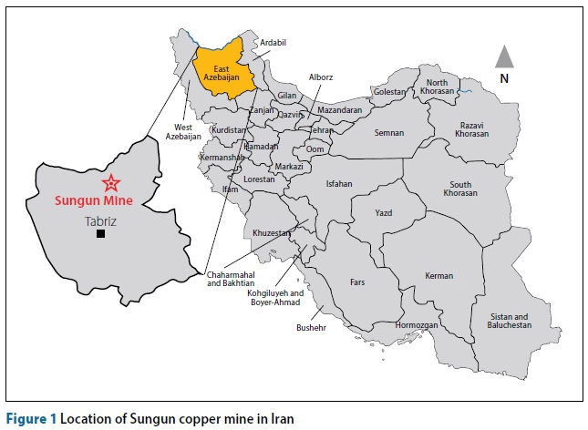
The Sungun porphyry copper mine is located 125 km north-east of Tabriz in East Azerbaijan Province of northwestern Iran at 43° 46' E and 38° 42' N (Figure 1). Having a proved reserve of about 410 million tons of copper ore with an average grade of 0.67% (Ghasemi et al 2012), this mine is the largest open copper pit in Iran, and it is expected to produce at least 380 million tons of tailings in about 30 years. As a result, extensive studies have been done on the safe and sustainable disposal of tailings in compliance with environmental laws in the basin of Zarnekabchay Stream located 6 km southeast of the mine. One of the main options for the construction of the Sungun tailings dam was the use of cycloned-sand tailings for elevation raise with the centreline method, which is addressed in this study.
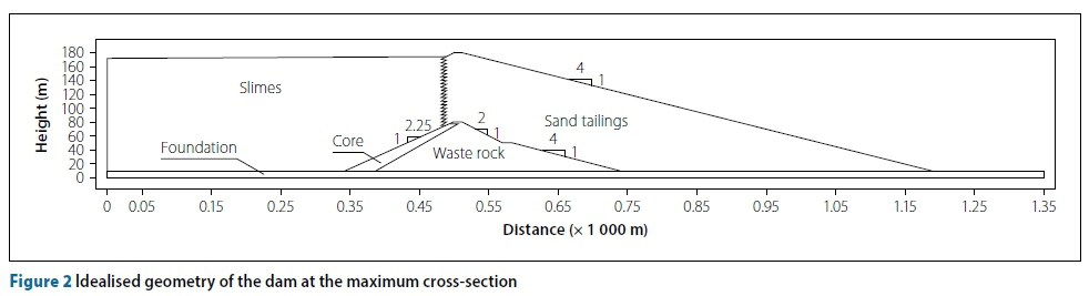
Figure 2 shows the idealised geometry of the dam at the maximum cross-section along with its main components. The main components of this dam are as follows:
1. Foundation: To simplify the behavioural analysis and make it applicable to other high centreline tailings dams, the foundation is assumed to have a smooth bottom and a thickness of 10 m (based on field investigations).
2. Starter dam: This structure is made of waste rock and an inclined clay core rising to a final height of 70 m. In reality there is a filter layer, which protects the core against piping failure; however this layer was not modelled because of its low thickness (1 m).
3. Sand dykes: This region is modelled with underflow tailings and a downstream slope of 4H:1V, an upstream slope of 2H:1V, a crest width of 10 m, and a height of up to 170 m.
4. Slimes: Considering the design of hydro-cyclones and separation of most of the coarse-grained materials from tailings slurry, impoundment materials are assumed to consist entirely of finegrained tailings (slimes). This section is modelled with a length of 490 m in a slope of 0.5%, and its freeboard is assumed to be equal to 5 m at the end of construction. It should be noted that the cycloned-sand/slimes interface does not include any low permeability core/ barrier system.
CONSTITUTIVE LAW AND MATERIALS PROPERTIES
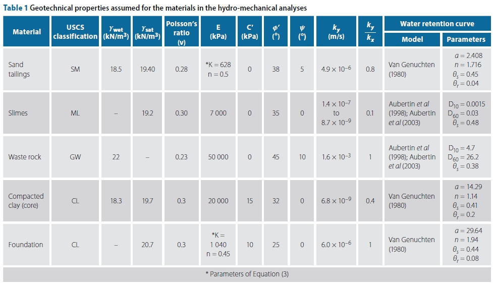
The geotechnical properties assumed for the materials in the hydro-mechanical analyses are given in Table 1. All the materials are assumed to behave according to the elastic perfectly plastic constitutive model. SIGMA/W uses the Mohr-Coulomb yield criterion as the yield function (Krahn 2012):
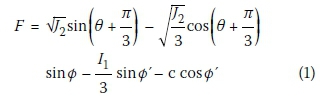
where J2is the second deviatoric stress invariant, 6 is the lode angle, and I1is the first stress invariant. The plastic potential function (G) employed in the software is similar to the yield function, except that in Equation (1) the dilation angle, y, is used instead of the effective friction angle, Ø' (Krahn 2012). The suction influence on the strength can be obtained from Equation (2) (Krahn 2012):
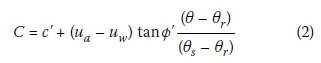
where c' is the effective cohesion, Өs and Өr are the saturated and residual volumetric water contents, Ө is the volumetric water content, and (ua - uw) is the matric suction.
The non-linear elastic modulus of sand tailings and the foundation are calculated with Equation (3) (Byrne et al 1987):
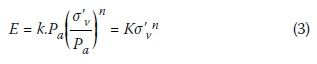
where σ'v is the vertical effective stress, Pa is the atmospheric pressure, and K and n are the coefficient and power. Based on the results of Rowe cell consolidation tests, the average elastic modulus of slimes is calculated to be 7 000 kPa, which is within the range of assumptions or measurements reported by Liang and Elias (2010), Jaouhar et al (2011), L. Bolduc (2012) and Ferdosi et al (2015b). Based on the assumptions of L-Bolduc and Aubertin (2014) and Ferdosi et al (2015a), the elastic modulus of waste rock is assumed to be 50 000 kPa.
To determine the failure parameters, the effective friction angle of sand tailings is obtained from anisotropically consolidated undrained (CK0U) triaxial shear tests conducted over a range of densities and cell pressures. In addition, given the small difference between (' values of sand tailings and the slimes produced in hardrock mines (Bussière 2007), the effective friction angle of slimes is assumed to be 35°, which is within the range of results reported by Volpe (1979) and Vick (1990) for copper slimes. In view of the discussions by Ferdosi (2014) and based on the assumption of Ferdosi et al (2015a), p' of waste rock is assumed to be 45°. Moreover, p>' and c' of the core and the foundation materials are determined based on the results of consolidated drained (CD) triaxial shear tests.
Based on the results of constant head permeability tests, the average vertical permeability of sand tailings with a void ratio of 0.82 is determined to be kv= 4.9 X 10⁻⁶ m/s. The permeability of slimes is obtained by two methods: (a) measuring directly at the end of every stress increment in a Rowe cell consolidation test, and (b) using the coefficient of consolidation (cv), which is within the approximate range of 10-7-10-8 m/s in the stress of 1-640 kPa. The results of consolidation tests show that the effective vertical stress function (void ratio) - saturated permeability of tailings can be well expressed by an exponential function in the form of Equation (4):
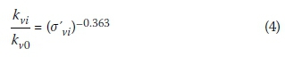
where kvi is the permeability coefficient at each stress increment, kv0 is the initial permeability coefficient and σ'v is in kPa. Additionally, given the layered nature of tailings (Sarsby 2013), the anisotropy ratio (kv / kh) is assumed to be 0.8 for sand tailings (based on the discussions of Klohn (1979); Saad & Mitri (2010a, 2010b)) and 0.1 for slimes (based on the discussions and results of Vick (1990); Abadjiev (1976); Vermeulen (2001); Saad & Mitri (2010a, 2010b)).
Based on the test results of L-Bolduc and Aubertin (2014), permeability of waste rock is assumed to be 1.6 x 10⁻³ m/s, which is in the range of results of other researchers (L-Bolduc & Aubertin 2014).
To obtain the unsaturated parameters, the water retention curve of sand tailings is determined by laboratory tests, and is then curve-fitted using the Equation (5) (Van Genuchten 1980):
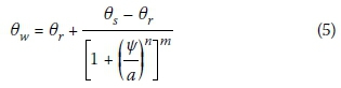
where Өw is the volumetric water content at different suctions, Ψ is the negative pore water pressure, and a (in kPa), n, and m are the curve fitting parameters. The parameter m is assumed to be equal to 1 - 1/n (Krahn 2012). For the core material, parameters a and n are determined using the equations suggested by Tinjum et al (1997) for compacted clays, and the retention curve of the foundation material is assumed to match the default curve provided in SIGMA/W for clays containing sand and gravel. In addition, the retention curve of slimes and waste rock is estimated using the modified Kovacs model. This model was first introduced by Aubertin et al (1998) for tailings from hard-rock mines, and was later developed for other soils (Aubertin et al 2003). The unsaturated permeability function of all the materials is determined based on their retention curves and on the equation provided by Van Genuchten (1980).
NUMERICAL ANALYSIS
Coupled analysis
SIGMA/W is a computer program for solving two-dimensional soil consolidation problems by using fully coupled analysis (Krahn 2012). In this analysis, each node of element grid (mesh) is assigned three equations, two of which concern the displacements (horizontal and vertical) while the third expresses the flow. Variations of displacement and pore water pressure can be determined by solving these three equations simultaneously.
Constitutive equation of the soil structure
Equation (6) shows the strain-stress development of an unsaturated soil in two-dimensional space (Fredlund & Rahardjo 1993):
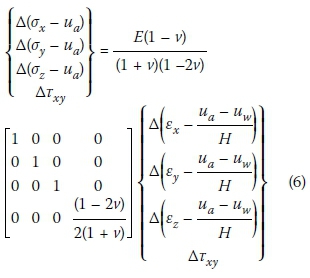
where ε is the normal strain, y is the shear strain, a is the normal stress, γ is the shear stress, ua is the pore air pressure, uw is the pore water pressure, £ is the elastic modulus of the soil structure, v is the Poisson's ratio, and H is the modulus of unsaturated soil for soil structure in regard to matric suction (ua - uw), which can be obtained by using the procedure described by Chen et al (2014).
Flow equation for water phase
Two-dimensional water flow in saturated-unsaturated soil is solved with Darcy's law (Fredlund & Rahardjo 1993):
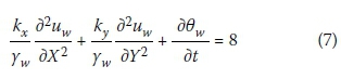
where kx and ky are the permeability on the horizontal and vertical directions, uw is the seepage velocity, 6w is the volumetric water content, yw is the unit weight of water, and t is time. The volumetric water content of elastic materials is determined by Equation (8) (Darkshanamurthy et al 1984):
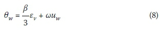
where
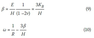
where KBis the bulk modulus and R is a modulus relating the change in volumetric water content to the change in matric suction, and equals the inverse of the slope of the soil-water characteristic curve (Krahn 2012).
Staged construction and boundary conditions of the base model
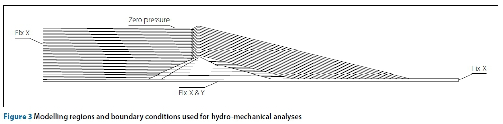
Figure 3 shows the regions and boundary conditions of the base model in the last stage of construction. In general, staged construction of the dam is modelled in three phases.
1. In situ analysis: To determine the initial stresses in the foundation, the volume of each element is multiplied by its corresponding unit weight, and the resultant force is exerted vertically on the nodal points. SIGMA/W determines the horizontal stresses using the coefficient of earth pressure at rest, k0=v'/(1 - v') (Krahn 2012). In the next phases, coupled analysis is conducted to determine the pore water pressure developed in the foundation due to staged construction of the starter dam, impoundment and dykes.
2. Starter dam: In view of the modelling approach, investigations and results provided by Naylor et al (1988), Zomorodian et al (2006) and Elia et al (2011), the fully coupled analysis of staged construction of the starter dam is performed by assuming seven 10 m thick layers. Furthermore, the total construction time of this structure is assumed to be two years.
3. Dykes and impoundment: Once the starter dam has been modelled, slimes are disposed of into impoundment and sand dykes constructed downstream. The fully coupled analysis of dykes and impoundment is performed by assuming 33 and 32 layers 5 m thick respectively. The total duration of this operation is assumed to be 30 years, with an annual elevation rise of 5.67 m.
Concerning the boundary conditions, in the in situ analysis the initial water surface is defined to be at the level of the ground surface in order to produce hydrostatic water pressure in the foundation. In addition to displacement boundaries, for which the method of assignment in all the analyses is illustrated in Figure 3, the coupled analysis also requires a hydraulic boundary condition. For this purpose, when a new layer is added to the core and slimes, the boundary condition of zero pressure (p = 0) is assigned to the upper boundary of this layer. With this approach, variations of water level are modelled with the rise in the elevation of materials, and the surface of the new layer can be drained. With the addition of the weight of each new layer, the resulting increases in the pore water pressure in the previous layers and the loading-induced consolidation are calculated simultaneously using the coupled analysis.
Meshing
In view of the inclined geometry of the core, mesh is developed in the form of a rectangular grid of quads, which is well suited for four-sided regions according to the software manual (Krahn 2012). Other regions have an unstructured quad and triangle mesh, which has been recommended for various geometries (Krahn 2012). Additionally, triangular and rectangular elements are assigned with 3 and 9 Gauss points respectively to enhance the accuracy.
Based on the results of mesh convergence analyses, dykes, impoundment and foundation are modelled with 5-m elements, and layers of starter dam are modelled with 10-m elements. This mesh consists of 6 246 nodes and 6 064 elements in total.
Other models
The previous section explained the geometry, material properties and method of analysis for the base model. Using this base model as the basis of work, the hydro-mechanical behaviour of the dam under the conditions described in Table 2 is studied. As this table shows, in Models 1 and 2 the effect of foundation permeability, in Models 3 and 4 the effect of raising rate, in Models 5 to 8 the effect of anisotropic permeability of slimes, in Models 9 and 10 the effect of changes in downstream slope, and in Model 11 the effect of the presence of permeable bedrock on the structural response are investigated. Models 5 and 8 are very unlikely to occur, and they are only analysed because of their conceptual utility. Moreover, apart from the differences listed in this table, all the models use the same material properties, modelling technique and analysis conditions previously explained for the base model.
RESULTS AND DISCUSSION
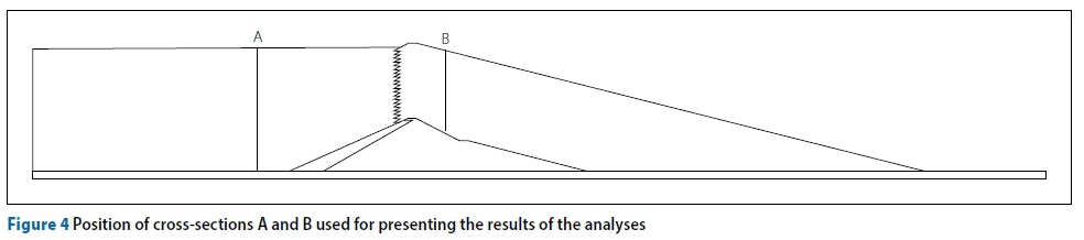
Based on the discussions of Saad and Mitri (2010a, b), the hydro-mechanical behaviour of the tailings dam during staged construction, in terms of pore water pressure developed in the impoundment and horizontal displacement of the dam body, was evaluated. All outputs were obtained for the base model as well as for the other models in Table 2, and the results of these models are compared. Two cross-sections, A and B (see Figure 4), were selected for detailed study of the pore water pressure in the impoundment and the horizontal displacement in the dam body respectively. The position of these two cross-sections allows them to provide useful information on the performance of the impoundment and the dam body.
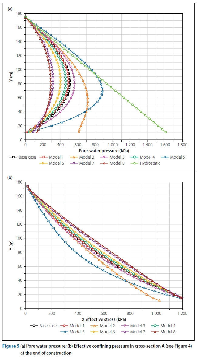
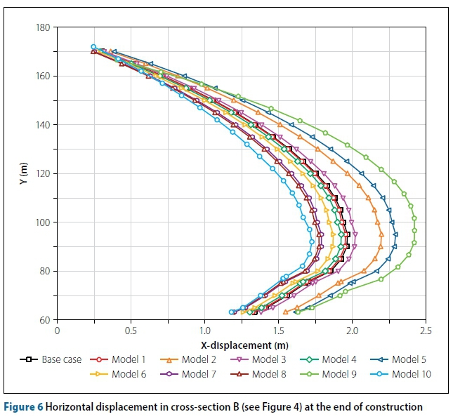
Figure 5 shows the pore water pressure and the effective confining pressure in cross-section A at the end of construction in Models 1-8 and the base model, and Figure 6 shows the horizontal displacement in cross-section B at the end of construction in all the models (excluding Model 11).
The base model
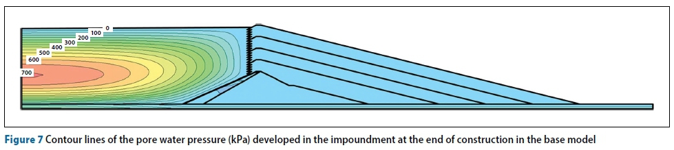
Figure 7 shows the contour lines of the pore water pressure developed in the impoundment at the end of construction in the base model. The peak PWP has developed in the middle of the impoundment at the approximate range of (0.3-0.5) H. This is due to the permeability value of the foundation and the possibility of drainage at the impoundment surface, which cause the PWP to dissipate more quickly in the upper and lower layers than in the middle layers. This can also be seen in cross-section A in Figure 5(a). The trend of PWP change in this cross-section is similar to that reported by Gassner and Fourie (1998) for the case where the bottom of the tailings was allowed to drain. At heights above 80 m, the pore water pressure in cross-section A exceeds the confining pressure, and the materials have an undrained-like behaviour (see Figure 5). In addition, at all heights, the PWP in cross-section A is less than the hydrostatic pressure (Figure 5a).
Figure 8 shows the contour lines of the horizontal displacement of the dam at the end of construction. The maximum displacement in the dykes (1.8-2.0 m) is observed in the upper section and downstream of the starter dam in the range of (0.35-0.6) H. This range is similar to the results of the analysis conducted by Törnqvist and Lindquist (2016) for a high tailings dam with similar geometry.
Effect of foundation permeability
The results of field tests conducted by drilling boreholes in the foundation indicate that the coefficient of permeability is in the range of 10-7-10-3 m/s. Given that the obtained field data has no specific distribution, the effect of permeability of the foundation on the hydro-mechanical behaviour was investigated by assuming a fixed value for this parameter.
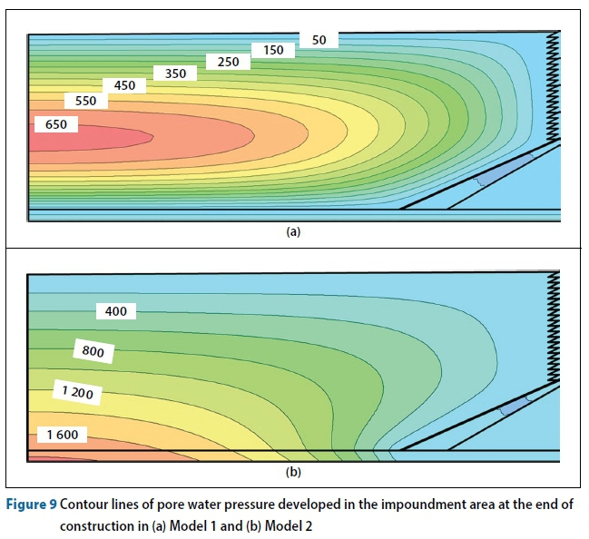
Based on the contour lines of the pore water pressure in the impoundment of Models 1 and 2 (Figure 9), several results can be inferred. First, there is little difference between the results of the base model and Model 1, both of which have a foundation with "low" permeability, and the maximum pore water pressure in Model 1 is about 50 kPa lower than that in the base model. This is while the permeability of the foundation has increased a hundredfold. In Model 2, where the foundation permeability is in the category of "very low", the peak pore water pressure in the impoundment area has reached more than 1 600 kPa. In addition, in this model the bulb of maximum pore water pressure area has shifted closer to the foundation, because of the much lower potential for drainage of excess pore water through the foundation. This is similar to the results obtained by Saad and Mitri (2010a, 2010b) and Ormann et al (2013) for upstream tailings dams with low permeable foundations, where the bulb of maximum pore water pressure has been reported to be in the range of approximately 20 to 30% of the impoundment floor.
According to Figure 5, there is very little difference between the base model and Model 1 in terms of pore water pressure and effective confining pressure in cross-section A. This result indicates that, as long as the foundation has a "low" permeability, the pore water pressure of the impoundment is not very sensitive to changes in the permeability coefficient of the foundation. However, in Model 2, in addition to pore water pressure being greater than the base model and closer to the hydrostatic pressure, there is a much wider difference between the effective confining pressure and the pore water pressure. In other words, in cross-section A, a large area of the impoundment (from a height of approximately 45 m from the floor) has an undrained-like behaviour. Nevertheless, in the two previous models, this condition is observed at heights above 80 m. The trend of pore water pressure change in this model and at this cross-section is similar to the results reported by Gassner and Fourie (1998) for the scenario where there was no drainage in the model floor.
Comparing the horizontal displacement in cross-section B of Models 1 and 2 with that of the base models, Figure 6 shows little difference between the results of Model 1 and the base model, as both have a maximum horizontal displacement of about 1.96 m; however, horizontal displacement of Model 2 in cross-section B reaches about 2.2 m. Therefore, as the permeability of the foundation decreases to a "very low" category, the PWP developed in the impoundment and the resulting seepage force applied to the body increase, which in turn result in increased horizontal displacement in the dam body. The above results show that more detailed studies are needed on the permeability parameters of the foundation of tailings dams.
Effect of raising rate
Duration of construction is an important factor in the stability of upstream tailings dams and this issue for this method of construction has been discussed in investigations such as those by Sarsby (2013) and Saad (2013), although Vick (1990) has not specified any limit for the raising rate of centreline tailings dams, and has only recommended a certain height limit for each individual elevation raise.
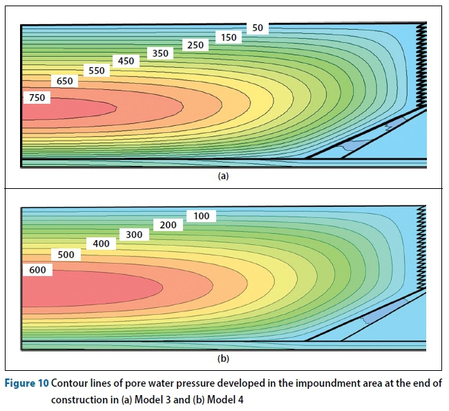
Figure 10 shows the contour lines of the pore water pressure in Models 3 and 4. It can be observed that the maximum pore water pressure (up to 800 kPa) has been developed in Model 3, but that in Model 4 the pore water pressure developed in the impoundment has decreased with the decrease in the raising rate down to a peak value of 650 kPa. Hence, in general the pore water pressure increases with an increase in the raising rate because faster construction means materials have less time for drainage. Obviously, at the end of construction, the dam built at a faster rate needs a longer time for the pore water pressure to dissipate.
In cross-section A (Figure 5), the pore water pressure of Model 3 is closer to the hydrostatic pressure than it is in Model 4 and the base model, but the PWP value and the effective confining pressure of all three models are almost the same, and at a height of above 80 m materials of all three models exhibit an undrained-like behaviour. In cross-sections closer than A to the dam body, all three models show less difference between PWP and a'x; therefore, although the maximum pore water pressure of the impoundment increases with the raising rate, the overall performance of the impoundment near the dam body does not depend much on this parameter. This causes the horizontal displacement in cross-section B of Models 3 and 4 to be almost identical to that which is observed in the base model (see Figure 6). On the whole, an increase (decrease) in the raising rate increases (decreases) the maximum x-displacement in this cross-section by roughly 10%. This amount of change is not sufficiently large to cause significant changes in the dam performance.
Effect of anisotropic permeability of slimes
It has been reported that seepage pattern is influenced more by the anisotropic permeability of tailings than by the definite value of this coefficient (Sarsby 2013). For this reason, some studies, such as those of Klohn (1979), Vick (1990) and Sarsby (2013), have investigated the effect of this parameter on the position of the phreatic surface under steady seepage conditions. However, the technical literature provides only sparse information regarding the effects of anisot-ropy in the permeability of slimes on the development of pore water pressure and overall performance of tailings dams during staged construction. Thus Models 5 to 8 are used to evaluate the performance of the dam. The resulting contour lines obtained for the pore water pressure in the impoundment are shown in Figure 11:
a. Maximum PWP of the impoundment has decreased from 1 400 kPa in Model 5 to 550 kPa in Model 8. This means that as kv/kh increases, the pore water pressure developed in the impoundment decreases because dissipation of excess pore water pressure along the vertical direction and flow of water towards the impoundment surface or the foundation become easier.
b. As kv/kh increases, the bulb of maximum pore water pressure shifts towards the foundation, perhaps because the flow of water towards the impoundment surface and the dissipation of excess pore water pressure along this path require less energy than does the flow towards the foundation. Thus water pressure dissipation in the upper sections of the impoundment takes less time than it does in the lower sections, and the bulb of maximum pore water pressure shifts closer to the foundation.
c. As kv/kh increases, so does the pore water pressure developed in the foundation. In Model 8, the PWP developed in the foundation even exceeds the maximum PWP developed in the impoundment. In this model, as the developed PWP decreases, the effective vertical stress in the impoundment increases and the weight of materials exhibits a greater effect on the foundation.
d. Comparison between the results of the base model and Model 6 with maximum PWP values of 750 and 550 kPa respectively shows that the slightest change in the anisotropy ratio triggers significant changes in the maximum PWP and its distribution in the impoundment, hence the overall performance of the impoundment is strongly affected by this parameter. Figure 5 shows a clear increase in the pore water pressure and decrease in the effective confining pressure with the decrease in kv / kh*Generally, as this coefficient decreases, the gap between the effective confining pressure and the pore water pressure grows, and a larger portion of the impoundment in cross-section A exhibits an undrained-like behaviour. In this situation, the profile of pore water pressure shifts closer to the hydrostatic pressure, and in some parts of Model 5 it even exceeds the hydrostatic pressure. The other notable point is the negligible effect of changing the anisotropy ratio from 0.5 to 1 (in Models 7 and 8) on the results in cross-section A.
Examination of Figure 6 for Models 5-8 shows that in general, as the kv / kh of tailings in the impoundment increases, horizontal displacement of the body decreases. The other notable results are as follows:
a. In Model 5 the greatest horizontal displacement in cross-section B is 2.4 m, but in other models it is within the range of 1.6 to 1.8.
b. Models 7 and 8 have similar displacements. These two models also have the same value of PWP developed in cross-section A at the end of the construction. Therefore in the range of kv / kh = 0.5 to kv / kh= 1.0, the effect of anisotropy in the permeability of slimes on the x-displace-ments of the studied dam can be ignored.
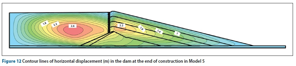
c. Comparison of Model 6 with the base model shows that, although the slightest change in permeability leads to significant changes in the pore water pressure, its effect on the horizontal displacement in the dam body is somewhat negligible. d. According to Figure 12, in Model 5 displacements in the impoundment are greater than those in the body and reach 2.8 m. In this model, given that the movement of excess pore water pressure is mostly horizontal, slimes are subjected to great horizontal seepage force, which leads to large horizontal displacements in the impoundment.
Effect of changing the downstream slope of the dykes
Based on the studies of Rico et al (2008) and Bowker and Chambers (2015), the downstream slope of the dykes is one of the most important factors controlling the stability of tailings dams, and slope instability has led to dam failure on many occasions.
Here Models 9 and 10 are used to evaluate the effect of changes in the downstream slope of the dykes on the horizontal displacement of the dam body. Figure 13 shows the contour lines of the horizontal displacement of the body at the end of construction in these two models. In Model 9, the maximum horizontal displacement in the body is 2.6 m, but in Model 10 this value has decreased by about 80 cm. Therefore, in general, decreasing the slope of the dam body triggers a substantial decrease in the horizontal displacements.
In Figure 6, a significant effect of a change in the downstream slope of the dam on the horizontal displacement can be observed. In cross-section B, the minimum and maximum displacements are observed in Models 9 and 10 respectively, and the results of other analysed models are all within the range bounded by the profiles of these two models. Comparison between the results of Models 9 and 10 with those of the base model shows that an increase in the slope changes the displacement more noticeably than does a decrease.
Effect of permeable bedrock
Some borehole samples obtained from the bedrock show extensive weathering down to depths of 10-25 m. Therefore in Model 11, the base of the foundation is assumed to have a drained boundary condition and the resulting effect on the pore water pressure of the impoundment is studied (Figure 14a). The maximum PWP in the impoundment of Model 11 is 50 kPa less than that in the base model, so there is actually little difference between the pore water pressures developed in these two models. In this model, with the construction of primary layers of the impoundment, the PWP is drained towards the bedrock. However, since the rate of elevation raise of the impoundment is faster than the time needed for complete drainage, the movement of water towards the bedrock occurs at a slower rate, and the PWP becomes almost similar to that of the base model. Consequently, the seepage force exerted on the dam body is almost the same as that in the base model, and both models have almost similar horizontal displacements in cross-section B (see Figure 14b). Thus it can be seen that the great height of the impoundment in comparison to the foundation, assuming a drained boundary condition at the lower boundary of the model, has little effect on the distribution and value of pore water pressure and horizontal displacement.
CONCLUSIONS
The results of this study can be summarised as follows:
1. Given the permeability value of the foundation in the base model, maximum pore water pressure was observed in the middle of the impoundment in the approximate range of (0.2-0.5) H. Meanwhile, peak horizontal displacement in the dykes was observed in the range of (0.35-0.6) H.
2. A decrease in permeability of the foundation has a significant effect on the distribution of PWP in the impoundment, an effect that is reflected in the increased value of the bulb of maximum pore water pressure and a shift in its position toward the bottom layers of the impoundment. This leads to an increase in the seepage force exerted on the dam body and triggers more horizontal displacements.
3. Although an increased raising rate increases the pore water pressure developed in the impoundment, its effect on horizontal displacement in the body of the analysed tailings dam is negligible.
4. Anisotropy in the permeability of slimes has a significant effect on the pore water pressure developed in the dam impoundment, as it was observed that an increase in the coefficient kv / kh decreased the maximum PWP in the impoundment. It is important to note that even a slight change in the anisotropy ratio leads to considerable changes in the distribution of the PWP and its maximum value. Therefore it is vitally important to pay due attention to this parameter, especially in dams in which pore water pressure has a significant effect on the structural stability (e.g. upstream tailings dams). However, from the perspective of displacement in the analysed tailings dam, when kv / kh is in the range of 0.5-1, this coefficient shows an insignificant effect on the horizontal displacement of the dam body and can therefore be disregarded.
5. Changing the downstream slope of the dam wall causes significant changes in its horizontal displacements. In fact, among the analysed parameters, this parameter has the greatest effect on the horizontal displacement. This result shows the importance of paying due attention to the outer slope in addition to other factors related to dam stability in staged construction.
6. Given the great height of the dam, the permeable bedrock has little effect on the horizontal displacement and pore water pressure of the dam.
7. It can be generally stated that, as the pore water pressure in the impoundment increases, so do the seepage forces and the hydraulic gradient exerted horizontally on the dam wall. This leads to greater horizontal displacements in the dam. This relation is validated by comparing Models 2, 3 and 5 with the base model. 8. From a qualitative perspective, the overall performance of the analysed tailings dam under different conditions is in good agreement with the results obtained by other researchers. This is particularly true for the pore water pressure developed in the dam impoundment. Therefore factors affecting the structural response of this dam are applicable to other -tailings dams.
Acknowledgement
The authors would like to thank Toos Ab Consulting Engineers Company for providing valuable information and data.
References
Abadjiev, C B 1976. Seepage through mill tailings dams. Transactions of the 12th International Congress on Large Dams, 29 March - 2 April, Mexico City, Mexico, 1: 381-393. [ Links ]
Aubertin, M, Mbonimpa, M, Bussière, B & Chapuis, R 2003. A model to predict the water retention curve from basic geotechnical properties. Canadian Geotechnical Journal, 40: 1104-1122. [ Links ]
Aubertin, M, Ricard, J-F & Chapuis, R P 1998. A predictive model for the water retention curve: Application to tailings from hard-rock mines. Canadian Geotechnical Journal, 35: 55-69. [ Links ]
Bowker, L N & Chambers, D M 2015. The risk, public liability, and economics of tailings storage facility failures. Available at: http://www.earthworksaction.com. [ Links ]
Bussière, B 2007. Colloquium 2004: Hydrogeotechnical properties of hard rock tailings from metal mines and emerging geoenvironmental disposal approaches. Canadian Geotechnical Journal, 44: 1019-1052. [ Links ]
Byrne, P M, Cheung, H & Yan, L 1987. Soil parameters for deformation analysis of sand masses. Canadian Geotechnical Journal, 24: 366-376. [ Links ]
Chen, Q, Zou, Y H, Tang, M & He, C R 2014. Modelling the construction of a high embankment dam. KSCE Journal of Civil Engineering, 18: 93-102. [ Links ]
Darkshanamurthy, V, Fredlund, D & Rahardjo, H 1984. Coupled three-dimensional consolidation theory of unsaturated porous media. Preprints, 5th International Conference on Expansive Soils, Adelaide, Australia. [ Links ]
Davies, M P 2002. Tailings impoundment failures: Are geotechnical engineers listening? Geotechnical News, September: 31-36. [ Links ]
Elia, G, Amorosi, A, Chan, A H C & Kavvadas, M J 2011. Fully coupled dynamic analysis of an earth dam. Géotechnique, 61: 549-563. [ Links ]
Ferdosi, B 2014. A numerical investigation of the seismic response of tailings impoundments reinforced with waste rock inclusions. PhD Thesis. Montreal, Canada: Ecole Polytechnique de Montreal. [ Links ]
Ferdosi, B, James, M & Aubertin, M 2015a. Investigation of the effect of waste rock inclusions configuration on the seismic performance of a tailings impoundment. Geotechnical and Geological Engineering, 33: 1519-1537. [ Links ]
Ferdosi, B, James, M & Aubertin, M 2015b. Numerical simulations of seismic and post-seismic behavior of tailings. Canadian Geotechnical Journal, 53: 85-92. [ Links ]
Fredlund, D G & Rahardjo, H 1993. Soil Mechanics for Unsaturated Soils. New York: Wiley. [ Links ]
Gassner, F & Fourie, A 1998. Optimizing the allowable rate of deposition on tailings dams. Proceedings, 5th International Conference on Tailings and Mine Waste '98, 26-28 January, Fort Collins, CO. [ Links ]
Ghasemi, E, Sari, M & Ataei, M 2012. Development of an empirical model for predicting the effects of controllable blasting parameters on flyrock distance in surface mines. International Journal of Rock Mechanics and Mining Sciences, 52: 163-170. [ Links ]
Hamade, T & Mitri, H 2013. Reliability-based approach to the geotechnical design of tailings dams. International Journal of Mining, Reclamation and Environment, 27: 377-392. [ Links ]
Hu, S, Chen, Y, Liu, W, Zhou, S & Hu, R 2015. Effect of seepage control on stability of a tailings dam during its staged construction with a stepwise-coupled hydro-mechanical model. International Journal of Mining, Reclamation and Environment, 29: 125-140. [ Links ]
Jaouhar, E, Aubertin, M & James, M 2011. Effect of mine waste rock inclusions on the consolidation of tailings. Proceedings, Pan-Am CGS Geotechnical Conference, 2-6 October, Toronto, Canada. [ Links ]
Klohn, E J 1979. Seepage control for tailings dams. In: Argall, G O & Brawner, C O (Eds). Proceedings, 1st International Mine Drainage Symposium, May, Denver, CO. San Francisco, CA: Miller Freeman Publications. [ Links ]
Krahn, J 2012. Stress and Deformation Modeling with SIGMA/W. An Engineering Methodology. Calgary, Canada: GEO-SLOPE International Ltd. [ Links ]
L-Bolduc, F 2012. Une étude sur l'utilisation des roches steriles comme inclusions drainantes dans les résidus miniers. MSc Dissertation. Montreal, Canada: École Polytechnique de Montreal. [ Links ]
L-Bolduc, F & Aubertin, M 2014. Numerical investigation of the influence of waste rock inclusions on tailings consolidation. Canadian Geotechnical Journal, 51: 1021-1032. [ Links ]
Liang, J Z & Elias, D 2010. Seismic evaluation of tailings storage facility. Proceedings, Australian Earthquake Engineering Society 2010 Conference, Perth, Australia. [ Links ]
Naylor, D J, Knight, D J & Ding, D 1988. Coupled consolidation analysis of the construction and subsequent performance of Monasavu Dam. Computers and Geotechnics, 6 (Special Issue on Embankment Dams): 95-129. [ Links ]
Ormann, L, Zardari, M A, Mattsson, H, Bjelkevik, A & Knutsson, S 2013. Numerical analysis of strengthening by rockfill embankments on an upstream tailings dam. Canadian Geotechnical Journal, 50: 391-399. [ Links ]
Ozcan, N T, Ulusay, R & Isik, N S 2013. A study on geotechnical characterization and stability of downstream slope of a tailings dam to improve its storage capacity (Turkey). Environmental Earth Sciences, 69: 1871-1890. [ Links ]
Psarropoulos, P N & Tsompanakis, Y 2008. Stability of tailings dams under static and seismic loading. Canadian Geotechnical Journal, 45: 663-675. [ Links ]
Rico, M, Benito, G, Salgueiro, A R, Díez-Herrero, A & Pereira, H G 2008. Reported tailings dam failures: A review of the European incidents in the worldwide context. Journal of Hazardous Materials, 152: 846-852. [ Links ]
Rykaart, M, Fredlund, M & Stianson, J 2001. Solving tailings impoundment water balance problems with 3-D seepage software. Geotechical News, 19: 50-54. [ Links ]
Saad, B. 2013. Mitigation measures for stability enhancement of tailing dams during construction. Proceedings, Geo-Congress 2013, Stability and Performance of Slopes and Embankments III, 657-669. [ Links ]
Saad, B & Mitri, H 2010a. Hydromechanical analysis of upstream tailings disposal facilities. Journal of Geotechnical and Geoenvironmental Engineering, 137: 27-42. [ Links ]
Saad, B & Mitri, H 2010b. Staged construction analysis of surface tailings disposal facilities. International Journal of Mining, Reclamation and Environment, 24: 44-63. [ Links ]
Sarsby, R W 2013. Environmental Geotechnics. London: Thomas Telford. [ Links ]
Tinjum, J M, Benson, C H & Blotz, L R 1997. Soil-water characteristic curves for compacted clays. Journal of Geotechnical and Geoenvironmental Engineering, 123: 1060-1069. [ Links ]
Törnqvist, S & Lindquist, A 2016. Stability analysis on a planned Mexican tailings dam. MSc Dissertation. Sweden: Uppsala University. [ Links ]
Van Genuchten, M T 1980. A closed-form equation for predicting the hydraulic conductivity of unsaturated soils. Soil Science Society of America Journal, 44: 892-898. [ Links ]
Vermeulen, N J 2001. The composition and state of gold tailings. PhD Thesis. University of Pretoria. [ Links ]
Vick, S G 1990. Planning, design, and analysis of tailings dams. Richmond, Canada: BiTech Publishers. [ Links ]
Villavicencio, G, Espinace, R, Palma, J, Fourie, A & Valenzuela, P 2013. Failures of sand tailings dams in a highly seismic country. Canadian Geotechnical Journal, 51: 449-464. [ Links ]
Volpe, R 1979. Physical and engineering properties of copper tailings. In: Committee on Embankment Dams and Slopes of the Geotechnical Engineering Division (Eds). Current Geotechnical Practice in Mine Waste Disposal. New York: American Society of Civil Engineers, 242-260. [ Links ]
Wei, Z, Yin, G, Wan, L & Li, G 2016. A case study on a geotechnical investigation of drainage methods for heightening a tailings dam. Environmental Earth Sciences, 75: 1-10. [ Links ]
Yuan, L & Lei, J 2015. The analysis of the seepage characteristics of tailing dams based on FLAC 3D numerical simulation. The Open Civil Engineering Journal, 9: 400-407. [ Links ]
Zhang, C, Liu, H, Yang, C & Wu, S 2016. Mechanical characteristics of non-saturated tailings and dam stability. International Journal of Mining, Reclamation and Environment, 32(1): 1-14. [ Links ]
Zomorodian, S M A, Sahebzadeh, K. & Haghighi, A T 2006. Effect of number of layers on incremental construction analysis of earth and rockfill dam. In: Berga, J M et al (Eds). Dams and Reservoirs, Societies and Environment in the 21st Century. Proceedings of the International Symposium on Dams in the Societies of the 21st Century. Boca Raton, FL: CRC Press. [ Links ]
 Correspondence:
M Naeini
Ferdowsi University of Mashhad, Azadi Sq, Mashhad, Khorasan Razavi, Iran.
T: +98 51 3662 7977
E: mhd.naeini@gmail.com
A Akhtarpour
Department of Civil Engineering, Faculty of Engineering Ferdowsi, University of Mashhad
Iran
T: +98 51 3880 5170
E: akhtarpour@um.acir

MAHDI NAEINI holds a BSc in Civil Engineering and an MSc in Geotechnical Engineering from Ferdowsi University of Mash had in Iran. As a part of his dissertation, he investigated the numerical behaviour of tailings dams. His research interests include laboratory and numerical investigations on the geotechnlcal properties of soils and tailings.

PROF DRAU AKHTARPOUR holds a BSc In Civil Engineering and an MSc and PhD in Geotechnical Engineering from Amirkabir University of Technology in Iran. He is an assistant Professor at Ferdowsi University of Mashhad in Iran. His research interests include geotechnical earthquake engineering and numerical investigations into geotechnical problems with regard to infrastructure such as dams, foundations and excavations.
* Corresponding author

