


Servicios Personalizados
Articulo
 Inglés (pdf)
 Articulo en XML
 Referencias del artículo
Indicadores

Links relacionados
-
 Citado por Google
 -
 Similares en Google
Compartir

 Permalink
Journal of the South African Institution of Civil Engineering
versión On-line ISSN 2309-8775
versión impresa ISSN 1021-2019
J. S. Afr. Inst. Civ. Eng. vol.59 no.2 Midrand jun. 2017
http://dx.doi.org/10.17159/2309-8775/2017/v59n2a2
TECHNICAL PAPER
Fatigue behaviour in full-scale laboratory tests of a composite deck slab with PBL reinforcement
P Lu; X Zhan; R Zhao
ABSTRACT
Studies on the fatigue behaviour of composite deck slabs are relatively few. To assess the fatigue performance of a composite deck slab at specific design loads, and to provide a reference for its design in fatigue, two full-scale models A and B of a composite deck slab were developed, comprising steel plates and steel-fibre-reinforced concrete slabs. These models will be a useful reference for experiments and design, and for developing codes. In this study we carried out fatigue experiments and focused on the fatigue performance of a composite deck slab in a column area, and the positive and negative bending moments. For the entire fatigue loading cycle, the overall performance of Models A and B was good, the overall stiffness of the composite deck slab was rarely attenuated, the stress levels in the steel members in relation to the fracture strength were not significant, and the steel member was in the stage of flexible work. Through comprehensive tests of Models A and B it was found that the original design exhibits good fatigue performance and meets the design requirements. The research results provide a basis for the design of a composite bridge deck slab in fatigue.
Keywords: steel truss arch bridge, steel-concrete composite deck slab, fatigue performance
INTRODUCTION
Perforated-stiffened-plate composite bridge deck slabs are a novel type of composite bridge deck slab. At the bottom sides of the slab, steel plates and concrete are connected through a perforated, stiffened plate that is known as a perfobond (PBL) shear connector. A perforated-stiffened-plate composite bridge deck slab combines the advantages of steel and concrete in a general composite deck slab. For bridge construction, a steel plate is used as permanent formwork. This design saves time during the installation and removal of the scaffolding setup formwork, and reduces the costs in relation to the construction cost of the whole steel beam structure. The steel plate and concrete slab are connected by PBL shear connectors to improve the composite effect of the slab, enhance the slab's stiffness and mechanical performance, and reduce deformation and slippage. The composite bridge deck slab - in conjunction with PBL shear connectors - is widely used in the construction of new bridges, maintenance activities and the reconstruction of existing bridges. Moreover, the composite slab has technical and economic advantages, and improves material performance and fast construction compared to other promising materials. However, despite the increasing use of PBL-shear-connected steel and concrete composite slabs, the bridges in which they are used are not immune to the long-term effects of moving loads. In particular, compared with a stud shear connector, a PBL shear connector is more prone to fatigue damage and failure. Composite deck slab structures are still in their early stages, as they have not reached the ends of their life cycles yet; thus, they have not yet exhibited the effects of fatigue loading. Since the more serious effects of fatigue loading have yet to appear, the fatigue problem has not been sufficiently addressed, nor systematically researched. Fatigue damage and failure decrease the reinforcement provided by the steel in a new bridge deck, which reduces the superstructure stiffness while increasing slipping. These effects seriously affect the vehicle capacity of the bridge structure. Therefore, an assessment of the fatigue performance of a PBL-shear-connected steel and concrete composite slab at highway loads has important academic and design potential, and will serve as a basis for future strategies for preventing or reducing damage due to fatigue loading.
Few studies of perforated-stiffened-plate deck slabs have been published. Ryu et al (2007) conducted a full-scale model test of a two-span continuous bridge deck slab to study the crack development of a fatigue-loaded composite deck slab. The results indicated that the cracks in a region with a negative bending moment were controlled within an allowable crack width for a specific fatigue load. The steel shuttering described in their paper was a profiled sheet; compared with steel-concrete bridge deck slabs, the perforated stiffened plates had a different arrangement. To verify the composite effect of the steel shuttering and the perforated steel plate combined with concrete, a test of a full-scale model of a perforated-stiffened plate deck slab was conducted by Kim and Jeong (2006). Their results showed that the perforated and stiffened plate effectively enhanced the composite effect. Their study primarily analysed the effect of the perforated steel plate for the entire composite bridge deck slab. Leitão (2011) developed a numerical model for the dynamic analysis of composite highway bridges using a finite-element method with mesh-refining technology, and achieved satisfactory results when assessing fatigue behaviour. To evaluate cracking in the vertical and horizontal joints of a composite bridge deck, Chang and Shim (2001) performed fatigue behaviour tests of the composite connection points of a continuous composite bridge. Their study also discussed methods of longitudinal pre-stressing. Although they did not conduct a thorough analysis of the effects of fatigue at the connection points on the entire composite bridge deck slab, their results provide a reference for the study of the fatigue behaviour of perforated steel plates, including the junctions of the underside and side steel plates. Allahyari et al (2014) investigated the behaviour of bridge decks for a static load applied to the centre of the deck. To evaluate the dynamic properties of the decks, they experimentally investigated the dynamic properties of exodermic bridge decks with alternative PBL shear connectors. Millanes et al (2014) investigated the design of a composite steel-concrete deck for a long railway bridge. Gara et al (2013) investigated the effectiveness of various casting techniques used to control the tensile stresses in the slab during the construction of continuous steel and concrete composite bridge decks. Leitão et al (2013) carried out a fatigue analysis and predicted the lifetime of composite highway bridge decks under traffic loading conditions.
Wang and Jiang (2007) reviewed the fatigue problem of composite structures and the direction of future studies on composite structures. They argued that future studies should continue to focus on the mechanism of fatigue damage accumulation, damage identification, and fatigue reliability. Yang et al (2012) performed mechanical performance tests of a fatigue-loaded composite beam of a composite bridge deck. Their results indicated that the fatigue failure mode of the composite beam specimens with a positive bending moment was the crushing of the concrete in the compression zone resulting from fatigue damage to the lowest steel beam. The fatigue life was directly related to the range of fatigue stresses; however, the upper and lower limits of fatigue loading had little effect on the fatigue life. Liu et al (2012) proposed a new composite bridge deck system and performed a theoretical analysis including a full-scale model test of a bridge deck. Their results showed that after 2 million cycles of fatigue loading at a load frequency of 5 Hz, no new cracks appeared in the composite deck, nor had the initial cracks expanded. Additionally, the stiffness of the test beam had not decreased, indicating that this composite bridge deck system had satisfactory fatigue properties. Zong and Che (2000) performed a fatigue test on a simply-supported continuous pre-stressed composite beam. They also analysed pre-stressed composite beams constructed from different types of concrete at different magnitudes and orders of pre-stressing. They drew some valuable conclusions by summarising the fatigue test results of the pre-stressed composite beams, discussing the maintenance of the steel members and stud connectors, and proposing a principle for the corresponding fatigue strengths.
For the fatigue of steel-concrete composite bridge decks, the theoretical analyses and experimental results provided by the above-mentioned studies are in agreement regarding fatigue-loaded steel-concrete composite bridge decks. However, the individual behaviour of various combinations of steel-concrete composite bridge decks is quite different, i.e. different combinations of materials and forms lead to different forms of fatigue behaviour. Additionally, fatigue test results are discrete. Therefore, many tests are needed to explore the mechanical behaviour of perforated, stiffened composite slabs. There are relatively few studies of fatigue performance and the corresponding design for novel composite bridge deck slabs. Many theoretical and technical problems still have not been solved, such as the failure mechanism, mechanical behaviour, load-bearing capacity, and deformation of novel composite bridge deck slabs under fatigue-loading conditions. Therefore, considering the variety of steel-concrete bridge decks and fatigue problems, the present study aims to evaluate the fatigue performance of composite bridge decks under highway loading conditions using the Dongping Bridge in Guangdong as a case study.
In this study, we conducted a model test and simulation analysis to evaluate the fatigue performance of a perforated stiffened deck slab at a highway load. We also propose some important indicators of fatigue performance, provide a reference for composite materials and forms, and assess their superior mechanical behaviour to validate the effectiveness of the proposed deck system for bridge applications. Our study contributes to the understanding of fatigue-induced damage or failure of bridge deck structures. The results of this study have important theoretical value and practical value for the optimisation, design and theoretical analysis of composite deck slabs.
TEST MODEL
Engineering background for the fatigue tests
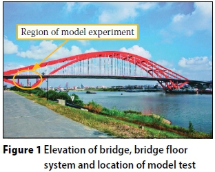
The main span of the Dongping Bridge (43.5 m + 95.5 m + 300 m + 95.5 m + 43.5 m) in Guangdong is a half-through steel truss arch bridge with a full length of 1 322.2 m. The steel boxes and concrete slabs are connected by PBL shear connectors. The grid beams consist of three main longitudinal girders, secondary longitudinal girders, main beams and secondary beams. Perforated-stiffened-plate composite bridge deck slabs were erected on the grid beams. Each slab has a minimum thickness of 12 cm and a maximum thickness of 20 cm. The overall layout of the Dongping Bridge and the testing zone of the composite bridge deck are shown in Figure 1.
The Dongping Bridge uses a composite deck-binding system with a space grillage design. Under the sustained action of moving loads, the longitudinal shear performance of the perforated and stiffened composite bridge deck slabs will be significantly degraded, and the degradation in the performance of the PBL shear connectors will reduce the composite effect of the composite bridge deck slabs. As a consequence, the load-bearing capacity and stiffness of the composite bridge deck may be reduced, which will affect the mechanical behaviour. Under such conditions, fatigue failure of the composite bridge decks will occur once the fatigue damage has escalated to a certain point. To assess the fatigue performance of the composite decks of the Dongping Bridge, we performed fatigue experiments and a numerical simulation in an area comprising positive and negative bending moments.
Actual bridge model selection
Domestic and international research indicates that the stress amplitude Δσ and the number of cycles N are the predominant factors affecting fatigue strength. Considering that the bridge deck span in the column area is larger, the most unfavourable girder beam in the bridge deck in the column area was selected for the analytical model of an actual bridge. Owing to the large span of the column area of the bridge, according to Saint-Venant's principle to relax the boundary condition, the longitudinal range of the column area and the transverse range between two main girders were selected as the objects of study for a simplified analysis problem. The focus was the fatigue performance of the composite deck slab in a column area comprising positive and negative bending moments. The elevation and plan of the model structure described above are shown in Figures 2(a) and 2(b).
Design of the experimental model
According to the study topics, two types of models - denoted as Models A and B - were constructed. Model A simulated the region of the bridge structure with a negative bending moment, which includes a secondary beam and concrete slabs. Model B simulated the region of the bridge structure with a positive bending moment, which includes the area between two beams. Models A and B were constructed to perform full-scale-model tests of the composite decks of the Dongping Bridge.
The two models were constructed using structural dimensions that were consistent with the actual bridge structure, except for the plate length L and plate width B. The geometry of Model B includes L and B as the objects of study. According to the experimental requirements and conditions, L = 5 000 mm and 6 000 mm for Models A and B respectively. The plate widths for Models A and B were selected according to a formula for the effective width of a concrete composite beam slab (JTT 1986; BS 1980). The calculated span of the actual bridge was 8 000 mm, the centre-to-centre distance of the adjacent secondary beams was 3 325 mm, and the top flange of the secondary beams was 706 mm.
The calculated width of the concrete slab was determined in accordance with the comparative results of the following four principles:
■ The first principle is based on the calculated width of the concrete slab, the sum of the width of the top flange and 12 times the thickness of the flange, and the minimum value of one of the three following items: a third of the span, the clear distance between two subbeam plate brackets, or 12 times the thickness of the top flange of the subbeam.
■ The second principle is based on the minimum value of one of the three following items: a third of the span, the centre distance of two subbeams, or the sum of the width of the top flange and 12 times the thickness of the top flange of the subbeam.
■ The third principle is in accordance with the CP117 specification based on the minimum value of the following three values: a third of the span, the centre distance of two subbeams, or the sum of the top width of the plate bracket and 12 times the flange thickness.
■ The fourth principle is in accordance with the BS 5400 specifications, with which the size of the model design is calculated.
According to comparative results of the four principles, the size of Model B was determined to be 2 146 mm. The size of Model A is 2 400 mm x 5 000 mm, and the size of Model B is 2 400 mm x 6 000 mm. The cross-sections of Models A and B and the loading positions are shown in Figures 2(c) and 2(d).
DESIGN OF THE FATIGUE MODEL TEST
Determination and theoretical analysis of fatigue loads
The stress conditions of the actual concrete plate were the focus of the present study. First, we ensured that the stress conditions of the top concrete plate were consistent with those of an actual situation when we determined the loading scheme of the test model by theoretical calculations. The stress loading was determined by theoretical calculation, hence the stress conditions of the concrete were verified for consistency with the actual situation. To align the stress conditions of the model with the actual structure, the upper limit load P and its loading location were determined. Vehicle loads of 20 t, 30 t and 55 t were used to calculate the fatigue vehicle loading with an influence line. Considering the effect of the deadweight of the bridge deck pavement, the magnitude of the stress at the lower limit fatigue load should be consistent with the bridge deck pavement of the actual bridge structure.
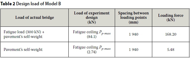
The theoretical results of the model test were obtained using an ANSYS finite-element model comprising spatial deck elements and solid elements. The model was based on 180 455 nodes and 207 65 elements. According to Table 1, the applied fatigue vehicle load was determined and the impact coefficient a = 0.295 was used. In the transverse direction of the bridge, the most unfavourable loading position was used, and the position of the vertical loading was based on the influence line of the control section of the four-span continuous beams. The finite-element model of Model B consisted of 31 250 nodes and 32 585 elements. The loading scheme of Model B was not determined until the stress conditions of the concrete slab were consistent with the actual bridge conditions. According to the comparative analysis results for each fatigue vehicle load in Table 1, the vehicle load of 30 t was selected as the control vehicle load for the actual bridge calculation. The analysis was carried out by allocating loads in a single lane. In the analytical model, the impact coefficient was determined to be 0.295, and the single wheel weight F on the actual bridge rear axle was determined to be 77.7 kN. According to the results of the analysis above, for the same stress distribution for Model B and an actual bridge under test loading, through an extensive space model analysis, the upper limit for the fatigue-test design load Pp-maxfor Model B was determined to be 84.10 kN, and the distance between the loading points was 1 940 mm. In addition, from the results of the analysis above, the stress in the actual bridge structure for a dead load is greater than that for Model B under its own weight. During the model test, the stress in the model at the lower limit of the fatigue load was set to be equal to that of the actual bridge at a constant load. Using the same analysis method with the upper limit of the fatigue-test design load, the lower limit of Pp_mi„ for Model B was determined to be 2.74 kN, and the distance between the loading points was 1 940 mm.
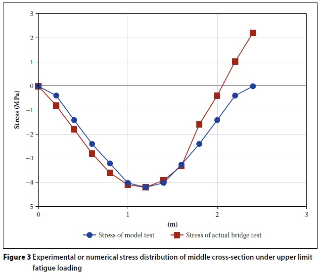
The stress distributions of the corresponding areas of the actual bridge and Model B at the upper limit of the fatigue vehicle load are shown in Figure 3. The longitudinal bending stress of Model B agreed well with that of the actual bridge. According to Figure 3, the compressive stress of the actual bridge model was larger than that of Model B within the longitudinal range of 0 mm to 350 mm. The longitudinal compressive stress of the actual bridge was smaller than that of Model B within the longitudinal range of 2 000 mm to 2 400 mm. Further, the longitudinal bending stresses of Model B and the actual bridge were consistent, except for the positions of loading and support. Additionally, they met the requirements of the model selection.
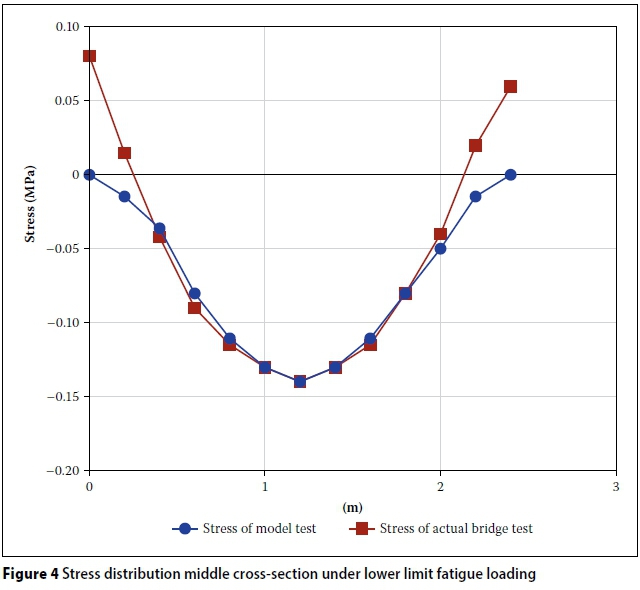
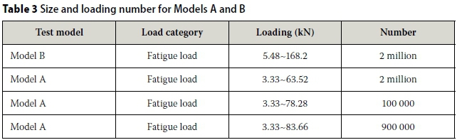
The stress distributions of the actual bridge and Model B at the fatigue limit loads are shown in Figure 4. According to Figure 4, the stress distributions laws and peaks of the longitudinal bending stress of Model B and the actual bridge are consistent, except for the locations of support and loading. Additionally, they met the requirements of the model selection. From a theoretical analysis, the test design loads of Model B are listed in Table 2, which indicates that the amplitude of the fatigue load of Model B is 5.48-168.2 kN, and the number of loading cycles is 2 million. The size of Model B and its loading positions are shown in Figure 2(d). The design idea of Model A is similar to that of Model B. The sizes of Models A and B and the number of loading cycles are listed in Table 3.
Determination of real bridge fatigue loads
China has not yet selected a standardised fatigue load spectrum for highway bridges, or established norms for selecting a vehicle for including fatigue loads. When determining the load spectrum of the decks of the Dongping Bridge, six fatigue loads based on the BS 5400 fatigue vehicle load (BS 1980); the United States AASHTO fatigue vehicle load (AASHTO 2005); the 20 t, 30 t, and 55 t fatigue vehicle loads specified by China (JTT 1986); and the BS 5400 axle loads
were compared. Moreover, the actual bridge model was simplified as a four-span continuous beam. The amplitude of the equivalent bending moment of the middle cross-section for the second span is listed in Table 1. According to a comparison of the results for different fatigue loads in Table 1, the 30 t fatigue vehicle load specified by China was selected as the standard fatigue vehicle load for the bridge model.
Production and programme design of the test model
The test model components consisted of steel plates and steel-fibre-reinforced concrete slabs. Model A had a length and width of 5 000 mm and 2 400 mm respectively. The thickness of the steel plate and the steel-fibre-reinforced concrete slab were 8 mm and 120 mm respectively. PBL strips were used in the shear connectors of the composite bridge deck slabs. These connectors have been widely used in composite structures to connect steel and concrete slabs. In this test model, the PBL connectors were embedded 400 mm along the transverse direction of the concrete slab, and 15 PBL connectors were used for the entire model. To strengthen the joint between the steel and concrete slabs, the hole in each of the PBL strips contained steel rebar with a diameter of 12 mm, and the weld joints of the steel-plate structure were strictly in accordance with the relevant standards. Furthermore, one half of the span of the weld joint of the PBL connectors and the steel plate was intermittently welded, whereas the other half was continuously welded. A large tonnage jack and an MTS servo system were used for the model test. A data accumulator was used to collect and store data on a computer for analysis.
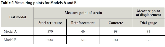
Owing to the complexity of the stress distribution, a majority of the plates were in a biaxial state of stress. Therefore, for the strain gauges of the measuring points, strain rosettes were used. A number of the strain gauges were fixed before the concrete was poured, while the other strain gauges were fixed after the model had been completed. For the entire model, a total of 514 strain gauges were used, of which 370 were attached to the steel structure surface, 46 were attached to the steel rebar surface, and 98 were attached to the concrete surface.
Displacements were measured by dial gauges, with a total of 35 dial gauges arranged around the test model. A constant-amplitude sinewave load was used for the fatigue test. The load frequency of the fatigue tester was 7.0 Hz, the number of loading cycles was 2 million, and the amplitude of the fatigue load was 5.48-168.20 kN. To monitor the stress and deformation of the measuring points during the fatigue test, data was obtained after the following numbers of fatigue loading cycles: 10 000, 50 000, 250 000, 500 000, 1 million, 1.5 million and 2 million. The test programme of Model B was similar to that of Model A. The measuring points and numbers for Models A and B are listed in Table 4.
FATIGUE TEST RESULTS
Fatigue test results for Model A
The basis for the test number was the proximity to the maximum deflection of 0.645 mm for a load of 83.66 kN during the static loading stage. A deflection analysis shows that the maximum deflection occurred at measuring point #15 under all working conditions. Measuring point #15 is located immediately below a loading point. The maximum deflection of the composite deck was 0.515 mm for a load of 63.52 kN after 2 million cycles. It should be noted that after 2 million cycles of fatigue loading, Model A had yet to show evidence of fatigue cracking. Additionally, the stiffness was not significantly reduced. To further investigate the fatigue performance of Model A, a load of 78.28 kN was applied to the model up to 100 000 fatigue cycles. After 100 000 cycles, the maximum deflection of the composite bridge deck plate was 0.63 mm, which is close to the maximum deflection after 2 million cycles. Therefore, we increased the fatigue limit load to 83.66 kN, and again applied it up to 900 000 cycles. After 900 000 cycles, the maximum deflection was 0.65 mm, which is close to the maximum deflection (0.645 mm) at the static loading stage (83.66 kN). The results showed that the maximum deflection of the composite deck was 0.63 mm for a load of 78.28 kN after 100 000 cycles. The maximum deflection of the composite deck was 0.65 mm under a load of 83.66 kN after 900 000 cycles loading. Hence, the stiffness of the composite deck did not decrease significantly.
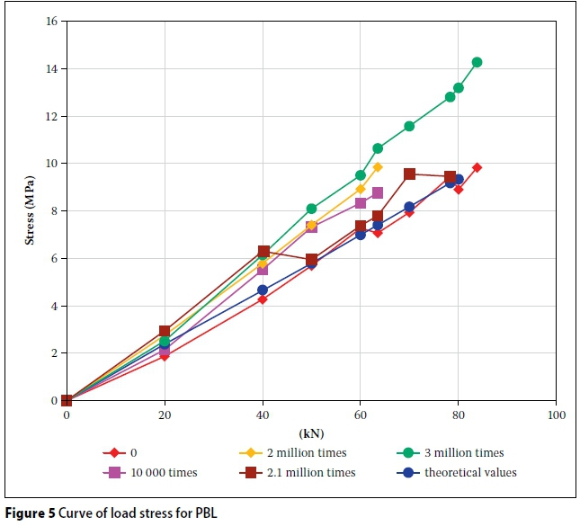
A stress analysis showed that for a load of 83.66 kN after 900 000 cycles, the steel plate surface, PBL connector and top concrete surface had maximum principal tensile stresses of 8.15 MPa, 14.28 MPa and 3.18 MPa, with maximum principal compressive stresses of 11.01 MPa, 6.78 MPa and 0.81 MPa, respectively. Each plate remained in an elastic stress state, and none of the stress levels of the plates were high, except for the concrete slabs. Figure 5 shows the change in the maximum longitudinal stress in the shear connectors with PBL strips based on a test using different numbers of fatigue loading cycles. After 2 million cycles, the measured stress increased somewhat; however, the results were mostly unchanged when compared with those after 10 000 cycles.
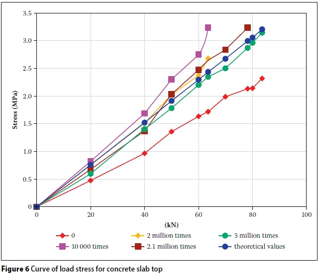
Figure 6 shows the change in the maximum longitudinal stress of the top concrete surface for different numbers of fatigue loading cycles. Figure 6 shows that, after 10 000 cycles, the stress was greater than that before fatigue loading; additionally, after 2 million cycles, the measured stress was basically the same as that after 10 000 cycles. Since the effect of the upper steel rebar was not considered in the theoretical calculation, the ANSYS theoretical results were greater than those of the static load test.
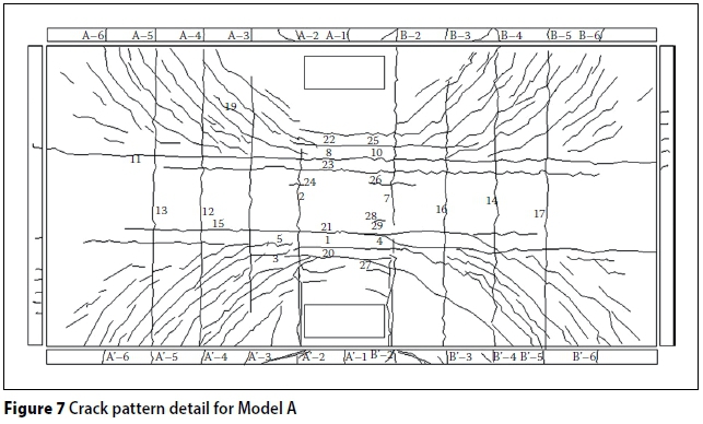
Testing indicated that after 10 000 cycles with an upper limit of 63.52 kN, four longitudinal micro-cracks appeared in the maximum transverse tensile stress zone of the top concrete surface. Meanwhile, a transverse crack appeared along the direction of the PBL connector for 100 mm from the mid-span of the model beam; the maximum width of the longitudinal cracks was 0.04 mm. As the number of fatigue load cycles increased, new cracks continuously emerged, and the existing cracks continuously expanded. The widths of the longitudinal and transverse cracks away from the mid-span section also increased, whereas the transverse cracks near the mid-span section did not increase in size. After 2 million cycles, the maximum width of the longitudinal cracks was 0.05 mm, and the maximum width of the transverse cracks was 0.10 mm. After 3 million cycles of fatigue loading, the maximum width of the longitudinal cracks was 0.055 mm, and the maximum width of the transverse cracks was 0.09 mm. Details of the crack pattern of Model A are shown in Figure 7.
Fatigue test results of Model B
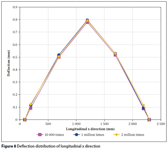
The amplitude of the fatigue load for Model B was 5.48-168.2 kN, and the number of fatigue loading cycles was 2 million. The deflection of the cross-section for 10 000, 1 million and 2 million cycles is shown in Figure 8. The results indicate that the overall stiffness did not change. The stress in the PBL shear connector for different fatigue loads increased as the number of fatigue loading cycles increased, and the stress was lower. The changes in the stress of two response points of the PBL shear connector are shown in Figure 9. All slabs were in elastic stress stage under fatigue loading, despite the increase in the number of fatigue loading cycles. In the fatigue loading stage, the deflection at the maximum deflection point for the model structure did not change, and the stresses in the steel plate and concrete plate were also lower. The strain data of the fatigue test show that the cracks in tension are in a stable state and do not have any more widespread diffusion.
Models A and B: Comparative analysis of the similarities and differences
The test programmes for Models A and B were different owing to differences between the structural characteristics of the two model experiment regions. In Model A, the steel I-beam mainly carried a negative bending moment, while in Model B, the region between steel I-beams primarily carried a positive bending moment. Two million cycles of fatigue loading were imposed onto the Model A region with a load of 20 t. After fatigue loading, 10 000 cycles of fatigue loading at 30 t, 900 000 cycles of fatigue loading at 30 t, and fatigue loading at 55 t were carried out. In addition, for Model B, 2 million cycles of fatigue loading at 30 t were loaded directly in the positive bending moment region. The results of the fatigue loading test for Models A and B show that after 2 million cycles, the maximum deflection of Model A was 0.515 mm, and the maximum deflection of Model B was 0.8 mm. The deflection of Model B was greater than that of Model A after 2 million cycles. The stress level for all types of loads for Model B was not greater than when considering the stress at each element in the model structure. For Model A, none of the stress levels at the elements were significant, with the exception of the concrete slabs. However, the stress levels were slightly greater than those for Model B. Concerning the cracks, before carrying out 500 000 cycles of fatigue loading, the number of cracks for Models A and B increased linearly. After 2 million cycles, the number of cracks for Model A increased slightly, but gently. The cracks in the bottom of the concrete slabs of Model B indicated that new cracks continuously emerged. From the above analysis, the test results for Model A were different than those for Model B with regard to the deflection, stress and cracks, because of the different types of model study and the fatigue loading, which led to differences in the mechanical behaviour of the positive and negative bending moment regions.
CONCLUSIONS
The mechanical behaviour of the Dongping Bridge deck structure was studied using experiments and finite-element analyses. The following conclusions were reached after evaluation of the experimental and finite-element analyses of the positive and negative bending moment regions of the composite bridge decks.
■ The test results for Model A revealed a maximum deflection of 0.65 mm, a maximum principal tensile stress in the bottom surface of the T-steel beam of 8.15 MPa, a maximum principal tensile stress in the PBL connector of 14.28 MPa, and a maximum tensile stress in the longitudinal rebar of 13.53 MPa. Additionally, the stress level was not high in the steel structure, with the entire structure remaining in the elastic stress state. At less than 500 000 cycles, the number of cracks increased linearly. However, after 500 000 cycles, there was only a small increase in the number of cracks. The overall stiffness of the composite deck exhibited no apparent attenuation after 2 million cycles of fatigue loading, and the maximum width of the longitudinal cracks in the top concrete surface was 0.05 mm.
■ The test results for Model B revealed a maximum deflection of 0.80 mm, which was 19% greater than before loading. However, the growth rate was only 2.6% from 10 000 to 2 million cycles. This indicated that the plate had good overall performance, and its stiffness was not attenuated after some initial loss of stiffness. The stress levels across all slabs were not high, and in the same sections the horizontal and longitudinal strain curves of the components appeared to be consistent for different numbers of cycles. During cyclic fatigue loading, the strain in the steel increased with the number of loading cycles, and cracks in the concrete slab formed or expanded.
■ The fatigue tests for Models A and B indicated that the steel-concrete composite bridge deck of the Dongping Bridge performed well overall, and the fatigue performance met the Chinese Code for the Design of Steel (GB 2003). Under normal conditions, the composite bridge deck of the Dongping Bridge will not experience fatigue damage.
■ The results of the fatigue tests of Models A and B indicate that the state of the loading levels are different for Models A and B. Model A was located in a negative bending moment area. For a load of 83.66 kN and after 3 million cycles, the maximum deflection of Model A was 0.65 mm, which is close to the deflection of 0.645 mm before cyclic loading. Model B was located in a positive bending moment area. For a load of 168.2 kN and after 2 million cycles, the maximum deflection was 0.80 mm, resulting in an increase of 19% compared to the deflection of 0.67 mm before cyclic loading.
ACKNOWLEDGEMENTS
The authors gratefully acknowledge financial support provided by the Science Foundation of China (Grant No 2016M60035), the Science Foundation of the Ministry of Housing and Urban-Rural Development of the People's Republic of China (Grant No 2012-K2-6), the Science and Technology Agency of Zhejiang Province (Grant No 2015C33222), the Science Foundation of Shanghai (Grant No 13R21421100) and Wenzhou City Science And Technology Projects (Grant No G20140017).
REFERENCES
AASHTO (American Association of State Highway and Transportation Officials) 2005. LRFD Bridge Design Specifications, 3rd ed. Washington, DC: AASHTO. [ Links ]
Allahyari, H, Dehestani, M, Beygi, Morteza, H A, Neya, B N & Rahmani, E 2014. Mechanical behavior of steel-concrete composite decks with perfobond shear connectors. Steel and Composite Structures, 17(3): 339-358. [ Links ]
BS (British Standard) 1980. BS 5400 Part 10: Code of Practice for Fatigue. London: British Standards Institution. [ Links ]
Chang, S P & Shim, C-S 2001. Continuous composite bridges with precast decks. Steel Structures, 1: 123-132. [ Links ]
Gara, F, Leoni, G & Dezi, L 2013. Slab cracking control in continuous steel-concrete bridge decks. Journal of Bridge Engineering, 18(12): 1319-1327. [ Links ]
GB (Chinese Standard) 2003. GB 50017-2003. Code for Design of Steel Structures. Beijing, China: China National Institute of Standardization. [ Links ]
JTT (Chinese Industry Standard) 1986. JTT 025-86 Specifications for Design of Steel Structure and Timber Structure Highway Bridges and Culverts. Beijing, China: China Communications Press [in Chinese]. [ Links ]
Kim, H-Y & Jeong, Y-J 2006. Experimental investigation on behaviour of steel-concrete composite bridge decks with perfobond ribs. Journal of Constructional Steel Research, 62(5): 463-471. [ Links ]
Leitão, F N, da Silva, J G S, da S. Vellasco, P C G, de Andrade, S A L & de Lima, L R O 2011. Composite (steel-concrete) highway bridge fatigue assessment. Journal of Constructional Steel Research, 67(1): 14-24. [ Links ]
Leitão, F N, da Silva, J G S & de Andrade, S A L 2013. Fatigue analysis and life prediction of composite highway bridge decks under traffic loading. Latin American Journal of Solids and Structures, 10(3): 505-522. [ Links ]
Liu, M, Shao, X, Zhang, Z & Hu J 2012. Experiment on flexural fatigue performance of composite deck system composed of orthotropic steel deck and ultra-thin RPC layer. Journal of Highway and Transportation Research and Development, 29(10): 46-53. [ Links ]
Millanes, F, Bordo Bujalance, E, Mansilla Dominguez, J L & Martin Suarez, J 2014. Archidona Viaduct: Composite steel-concrete deck for a long railway bridge. Structural Engineering International, 24(1): 122-126. [ Links ]
Ryu, H-K, Kim, Y-J & Chang, S-P 2007. Crack control of a continuous composite two-girder bridge with prefabricated slabs under static and fatigue loads. Engineering Structures, 29: 851-864. [ Links ]
Wang, P & Jiang, S 2007. Overview of fatigue damage for composite structure (bridge deck). Journal of Harbin Institute of Technology, 39(2): 694-698. [ Links ]
Yang, Y, Zhou, X & Xue, J 2012. Experimental study on fatigue behavior of composite girders with steel plate-concrete composite bridge decks. China Civil Engineering Journal, 45(6): 123-131. [ Links ]
Zong, Z & Che, H 2000. Fatigue behavior of pre- stressed composite steel-concrete beams. Journal of the China Railway Society, 22(3): 92-95. [ Links ]
 Correspondence:
P Lu
Faculty of Civil Engineering and Architecture
Zhejiang University of Technology
Hangzhou310014
PR China
T: +86 0571 88320153
E: pengzhenlu@zjut.edu.cn
X Zhan
Faculty of Civil Engineering and Architecture
Zhejiang University of Technology
Hangzhou310014
PR China
T: +86 0571 88320153
E: zhanxl@zjut.edu.cn
R Zhao
School of Civil Engineering
Southwest Jiaotong University
Chengdou 610011 PR China
T: +86 028 87601333
E: rendazhao@163.com

PROF PENG-ZHEN LU is an Associate Professor in the Faculty of Civil Engineering and Architecture, Zhejiang University of Technology, Hangzhou, China. He obtained his PhD from Southwest Jiaotong University. He has a broad interest in structural analysis and design, encompassing numerical modelling and experimental work. His major current interest is the modelling of the linear and nonlinear behaviour of composite bridges. A parallel development is composite structural application, including composite beams and pre-stressed composite beams, especially the calculation theory and analytical method for composite box beams. He also has an interest in specially shaped bridges, bridge evaluation and bridge strengthening, particularly as there are many old bridges in China.

PROF XIAOLI ZHAN is an Associate Professor in the Faculty of Civil Engineering and Architecture, Zhejiang University of Technology, Hangzhou, China. She obtained her PhD from the Harbin Institute of Technology. She has a broad interest in road and bridge structural analysis and design, encompassing numerical modelling and experimental work.

PROF RENDA ZHAO is at the School of Civil Engineering, Southwest Jiaotong University, China. He is also a vice-president of the China Institute of Civil Engineering. He obtained his BSc degree from Chongqin University, and his MSc from Southwest Jiaotong University. He has a broad interest in structural behaviour and experimental work.

