


Serviços Personalizados
Artigo
 Inglês (pdf)
 Artigo em XML
 Referências do artigo
Indicadores

Links relacionados
-
 Citado por Google
 -
 Similares em Google
Compartilhar

 Permalink
Journal of the South African Institution of Civil Engineering
versão On-line ISSN 2309-8775
versão impressa ISSN 1021-2019
J. S. Afr. Inst. Civ. Eng. vol.59 no.2 Midrand Jun. 2017
http://dx.doi.org/10.17159/2309-8775/2017/v59n2a1
TECHNICAL PAPER
Characterisation of rigid polyurethane foam-reinforced ballast through cyclic loading box tests
R F du Plooy; P J Gräbe
ABSTRACT
As train speeds and heavy haul axle loads constantly increase due to market demands, so do the stresses and strains experienced by track structures. This is especially true for track transitions that generate high dynamic forces on both the track and vehicles because of poor vertical track geometry and/or differing track stiffness values on either side of the track transition. Reducing differential settlement between the two track structures at a track transition is one method of improving the life of the track, and increasing maintenance intervals. In this study, rigid polyurethane foam was used to reinforce ballast. Tests were conducted using a dynamic hydraulic load frame and a single sleeper in a large ballast box subjected to heavy haul axle loads. Unreinforced, reinforced and 50% reinforced ballast layers of 300 mm depth were tested to approximately 5 000 000 load cycles. The results showed that rigid polyurethane foam-reinforced ballast exhibited in the order of 60% less settlement for a fully reinforced layer, and 42% less settlement for a half reinforced layer. The use of rigid polyurethane foam (RPF) to reinforce ballast has a number of benefits that could result in better track geometry and longer maintenance cycles, in turn resulting in lower life cycle costs.
Keywords: ballast, concrete sleepers, ballast settlement, ballast breakdown, rigid polyurethane foam, cyclic loading
INTRODUCTION
The objective of this study was to study the settlement behaviour and other track parameters through long-term, large-scale, cyclic loading box tests subjected to heavy haul axle loads (30 tons). It was hypothesised that the reinforcement of ballast using rigid polyurethane foam would lead to a reduction in ballast layer settlement, an increase in stiffness, reduced ballast breakage and an overall improvement in track performance.
Two main objectives of the study were, firstly, to characterise the properties of the ballast, polyurethane foam and the ballast-polyurethane-foam composite material and, secondly, to characterise the settlement behaviour of the ballast and polyurethane foam-reinforced ballast layer.
Only a ballast layer was modelled in the box test with no other foundation layers. Various test configurations were prepared, ranging from completely unreinforced ballast to fully reinforced ballast. Each sample was subjected to 5 000 000 load cycles at the specified load.
Settlement prediction models were compared to actual ballast settlement behaviour, and the validity of these settlement prediction models for use with polyurethane reinforced ballast samples was examined. Resilient sleeper deflection, ballast layer stiffness and ballast layer strain were all determined and compared. A number of sample material tests were also conducted to compare the material behaviour of rigid polyurethane foam and ballast reinforced with rigid polyurethane foam.
BACKGROUND
The most widely used track structure worldwide is the conventional or ballasted track structure. Typically, it consists of two main parts - the superstructure (i.e. rail, fastening system and sleepers) and the substructure (i.e. ballast, subballast and subgrade) as defined by Selig and Waters (1994).
Ballastless track structures are track structures that have been developed to mitigate the problems relating to the slow deterioration and subsequent settlement of the ballast material as a result of traffic loading. Ballastless track structures are typically divided into two main categories, namely ballastless track that provides continuous support to the rail, and ballastless track that provides discrete support to the rail. Ballastless track structures can result in maintenance costs that are 20% to 30% lower than ballasted track (Esveld 2001).
Track transitions occur where a ballasted track section changes to a ballastless track system or a ballasted track system on a structure. The abrupt change in track support that occurs at these locations has often been associated with accelerated rates of track geometry and component degradation, which in turn can lead to poor ride quality and increased maintenance demand (Read & Li 2006). When maintenance at these track sections is neglected, accelerated deterioration in track geometry can be expected. Agreement in the literature exists as to the possible mechanisms that affect the differential movement at track transitions. The problems at track transitions can be attributed to three primary factors (Sasaoka & Davis 2005):
■ Differential settlement
■ Differences in settlement characteristics
■ Discrepancies in track damping properties between adjacent sections.
Nicks (2009) categorised remedial measures aimed at reducing track transition impact forces as follows:
■ Limit approach track structure settlement.
■ Decrease modulus on bridge deck/ballast-less track structure.
■ Increase the modulus for the approach track.
■ Reduce ballast wear and movement.
■ Increase damping on bridge deck/ballast-less track structure.
When ballast has been in service for a significant period of time, it becomes damaged and contaminated, resulting in a change in the grading of the ballast which in turn leads to a reduction in performance. The process through which this occurs is known as fouling. Selig and Waters (1994) list the five causes of ballast fouling as:
■ Ballast breakdown
■ Infiltration from ballast surface
■ Sleeper wear
■ Infiltration from underlying granular layers
■ Subgrade infiltration.
Ballast fouling prevents the ballast from fulfilling its functions, and the extent of this loss in function is dependent on the amount and size of the fouling material. As the mass of sand and fine-gravel-sized fouling particles (0.075 mm to 19 mm) increases, the resilience to vertical deformation, as well as the void space, decreases. Fouled ballast is gap-graded. This results in a reduction in drainage and could make surface lining (i.e. tamping) operations difficult. As the void space is filled, the density of the ballast material increases. Should this material then be tamped, a higher rate of ballast settlement can be expected after tamping. An increase in the mass of clay and silt-sized particles (particle sizes smaller than 0.075 mm) also results in reduced drainage, leading to ballast erosion and subgrade attrition. When mixed with water, fine particles may form a slurry that is abrasive to the ballast material. Fouled ballast with high water content leads to higher rates of plastic strain in the fouled ballast.
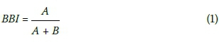
Ballast breakdown can be quantified by using a parameter known as the Ballast Breakage Index (BBI), and the ballast breakage can be quantified by comparing the plots of particle size distributions. As the number of breakages increase, the particle size distribution shifts to the left of the graph (see Figure 1), and the area between this new line and the original particle size distribution is considered as the breakage zone. Indraratna et al (2005) state that the breakage potential is considered to be the area between the original particle size distribution and an arbitrary reference line connecting the point between the intersection of (¿95 of the largest sieve size and the minimum particle size of 2.36 mm. Figure 1 shows the definition of the BBI parameters which are used in Equation 1.
The permanent deformation behaviour of ballast under cyclic loading is usually in the form of settlement. The settlement behaviour can be both elastic (such as initial settlement due to compaction) and plastic (due to breakage of ballast particles). The number of load cycles also has an effect on the permanent deformation, with the permanent deformation being a function of the logarithm of the number of cycles (Shenton 1974).
The variation in settlement behaviour between uncompacted and compacted ballast samples was compared, with the uncompacted ballast settling significantly more than the compacted ballast, along with the uncompacted ballast having greater first cycle axial strain development (2.8%) compared to 0.58% for the first cycle of the compacted ballast. Each additional cycle of loading caused an increment of plastic strain, but at a diminishing rate, varying from 0.24% after the first cycle to 0.001% after approximately 50 cycles (Indraratna et al 1997).
A number of equations have been proposed to describe the settlement behaviour of ballast. Selig and Waters (1994) compared a number of settlement prediction equations and found that, of the semi-log, hyperbolic, parabolic and power relationships, the best overall trend was represented by the power relationship of the form shown in Equation 2 and the logarithmic relationship shown in Equation 3.
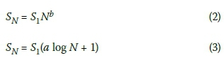
Where:
SN= settlement after cycles
S1= settlement after the first cycle
a and b are shape parameters.
Granular materials, such as railway ballast, experience problems over poor formations, due to the development of tensile strains at the formation interfaces. The continued rotation of the principle stresses causes ballast densification, and hence settlement. This increases over soft formations as a result of low track stiffness, which then induces ballast plastic strains. One method of improving the ballast layer, and reducing the amount of plastic strain and settlement is to reinforce the ballast layer (Woodward et al 2009).
A method of reinforcing or stabilising the ballast layer is the use of polyurethane foam. Keene et al (2012a) conducted a study into the characterisation of rigid polyurethane foam (RPF) reinforced ballast. RPF is an expanding polyurethane which is placed in the ballast layer (either through pouring or injection) and is then allowed to fill the ballast layer voids, preventing the infiltration of water and other contaminants. The RPF would further protect the structure from rearrangement and settlement. RPF is a cross-linked, closed-celled, thermoset material with a low density, and a number of the RPF material's properties are dependent on the density. RPF is typically supplied in two separate components - an A-component (polyether polyol) and a B-component (poly-isocyanate) are then mixed and applied.
Keene et al (2012b) summarised the mechanical property results of the work on polyurethane stabilised ballast (PSB) as follows:
■ PSB outperforms other track-substructure materials.
■ PSB typically had higher elastic deformational behaviour.
Furthermore, Keene et al (2012b) concluded the following with regard to the feasibility of using polyurethanes to stabilise track substructure:
■ Stabilisation does not have a negative impact on elastic response.
■ Injection methods that are currently employed are feasible for track stabilisation.
■ PSB can greatly increase the track mechanistic life cycle.
Keene et al (2013) conducted numerical modelling into the effect of polyurethane stabilisation on rail track response. The numerical model was used to determine the effects of various parameters, such as location, thickness and polyurethane properties, on the ballast layer and how resilient behaviour is influenced. A larger range of PSB moduli than observed in the laboratory was also incorporated into the numerical model.
The simulations by Keene et al (2013) showed that there are minimal changes in the strain of each substructure layer (i.e. ballast, subballast and subgrade) and no negative effect on the overall elastic response under loading due to the change in stiffness of the polyurethane reinforced areas. Specific material properties and structural components of the track system appear to have far greater influence on substructure elastic strain and track modulus than the integration of polyurethane reinforcement into the ballast layer.
Keene et al (2012b) report that, while rigid-compact polyurethane in rail infrastructure has been used, very few experimental and empirical methods have been developed for ascertaining the mechanical properties and life cycle characteristics of rail substructures that have been stabilised with polyurethane. The investigation into the injection of RPF into the rail substructure is an uncharted area. Standard laboratory tests for the fabrication and characterisation of polyurethane stabilised ballast (PSB) are aimed at contributing to research infrastructure. The overall objective is to reduce maintenance life cycle costs, increase rail freight load capacity and provide maintenance techniques that are not disruptive to railroad traffic.
EXPERIMENTAL WORK
The characteristics of the foam and ballast materials that were subjected to cyclic loading box tests and the details of the experimental work are described in the following sections of the paper.
Material properties
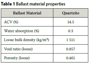
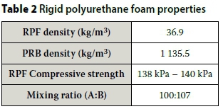
The rigid polyurethane foam that was used to reinforce the ballast was Elastopor* H 1311/1. The foam is supplied in two separate components, namely a Polyol-component (A) and an Iso-component (B). The polyol component is a mixture of polyetherpolyolls, stabiliser, catalyst, flame retardant and water. The iso-component is polymeric diphenylmethane diisocyanate (IsoPMDI 92140). The material properties of the rigid polyurethane foam (RPF) and the ballast material were determined prior to testing. An initial grading analysis and a loose bulk density determination were conducted on the ballast. RPF cylinders, and RPF reinforced ballast cylinders were cast and their load-deflection behaviour was tested in a universal testing machine. The ballast material properties are summarised in Table 1, with a summary in Table 2 of the various foam material properties.
Cyclic loading ballast box tests
A hydraulic MTS load frame with a maximum actuator capacity of 500 kN was used to apply the cyclic loading to the ballast samples. A large steel box was constructed, with internal dimensions of 2 400 mm long, 600 mm wide and 400 mm high. Each test consisted of a 300 mm ballast layer with a PY-sleeper for ballast loading. Linear variable differential transducers (LVDTs), with a full scale of 20 mm, were mounted onto the test frame at each sleeper end for local sleeper displacement measurement in addition to the internal actuator displacement measurement. The setup of a single sleeper on a 300 mm ballast layer in a steel box, simulating a section of track, is shown in Figure 2.
Each test was divided into primarily two phases, namely the initial phase and the consolidation phase. During the initial phase, large settlement values were recorded as a result of the settlement of the uncompacted ballast and the tests had to be paused to readjust the LVDTs to their measuring range. The loading during the initial phase consisted of a number of sub-phases where the load and loading frequency were incrementally increased during the initial 57 000 cycles. The final test setup is shown in Figure 3.
The second phase of the test consisted of the consolidation phase where a sinusoidal, cyclic 260 kN load (30 ton/axle loading) was applied to the sleeper for a total of 5 000 000 cycles. The magnitude of this cyclic load was obtained using the AREMA Manual of Railway Engineering standard specification. A maximum rail seat load of 60% of the axle load is recommended for a pre-stressed concrete sleeper at 760 mm sleeper spacing (Figure 30.4.1 in AREMA 2010). A dynamic factor of 1.46 was applied to the static load of 147 kN. A total of four tests were conducted, all at a test frequency of 10 Hz. The complete test record, summarising the various tests, is shown in Table 3.
During initial sample preparation it was discovered that, without restricting the movement of the ballast, the foam would expand and push the ballast particles apart. In Test 1, the 300 mm ballast layer was reinforced using RPF, and the expansion of the ballast and foam was not limited after pouring. During the preparation of Test 2, the expansion of the RPF in the ballast layer was limited by the placement of a sleeper on top of the ballast layer during the pouring process. Test 3 was a ballast test without any reinforcement applied. Test 4 was conducted using 50% reinforcement (i.e. bottom 150 mm reinforced and top 150 mm unreinforced).
Figure 4 shows the complete void filling of the RPF of the ballast layer to produce the reinforced ballast composite structure.
RESULTS AND DISCUSSION
Ballast settlement
The settlement results from the initial phase of testing are shown in Figure 5. A significant amount of settlement occurred in the initial phase of testing, due to the ballast layer being uncompacted at the start. From Figure 5 it can be observed that the unreinforced ballast (UR) experienced the greatest amount of settlement, as the particles were free to settle and undergo reorientation. The reinforced ballast (RB) test, where the foam was allowed to freely expand, showed similar initial settlement values, only exhibiting 3.5% less settlement than the unreinforced ballast during the initial phase of testing. Reinforcing half of the ballast layer (bottom 150 mm) resulted in a reduction in initial settlement of 54%. Limiting the expansion of the RPF reinforced ballast layer by placing a sleeper on the top of the layer during the pouring process resulted in the lowest initial settlement (33.8 mm) which represents 34% of the settlement observed in the unreinforced ballast test.
Following the initial phase, the main (consolidation) phase of the test was initiated. This phase consisted of the full test load being applied for 5 million load applications at a frequency of 10 Hz. During the initial phase of testing, the unreinforced ballast test produced the highest settlement. However, as shown in Figure 6, during the main phase of testing the unreinforced ballast layer settled the least (3.7 mm). The reinforced ballast layer with free expansion showed the largest amount of settlement during the main phase, settling a total of 12.9 mm. This is most probably as a result of the lack of inter-particle contact between the ballast stones. This lack of inter-particle contact can be explained by the fact that, during the RPF curing process, expansive forces were generated and these forces were significant enough to lift the ballast stones. Only once the foam-filled voids between the ballast stones were sufficiently compressed, was inter-particle contact restored.
Fully reinforcing the ballast layer resulted in a total settlement of 4.3 mm, while the ballast layer with 50% reinforcement settled 4.9 mm. The unreinforced, reinforced and 50% reinforced ballast layer tests all produced settlement values within 1.3 mm of one another.
The two settlement test phases were combined to obtain a total settlement value. The largest combined settlement was observed in the test with RPF reinforced ballast with free expansion, where a total combined settlement of 63.0 mm was observed. The unrein-forced ballast layer exhibited the second largest combined settlement of 55.6 mm, the vast majority of which occurred during the initial phase (92.9%). Figure 7 shows the combined settlement results, with the 50% reinforced ballast layer showing the second lowest total settlement (32.0 mm). The reinforced ballast layer with the RPF expansion limited showed the lowest combined settlement, with a total settlement of 22.3 mm.
The use of RPF as a means of reducing ballast settlement is a possibility, provided that the expansion of the foam into the voids of the ballast does not result in significant ballast particle uplift which could remove the inter-particle contact between the stones. By reinforcing 50% of a ballast layer, the total settlement experienced by the layer can be reduced by 58% compared to unreinforced ballast. Comparing the completely reinforced ballast layer (expansion limited) with the 50% reinforced layer, the former produced a 45% reduction in total settlement. A partially foam-reinforced layer would have the benefit of retaining the drainage, maintainability and other ballast characteristics that are lost when fully reinforcing the ballast layer.
Although some of the reinforced tests showed more settlement during the main phase of the test, the large reduction in initial consolidation settlement should also be noted as a primary contributor to the reduced total settlement. Allowing the free expansion of the polyurethane foam reinforcement should be limited, as increased settlement in all phases of testing was observed and was even outperformed by the unreinforced ballast. For use in the field, the foam should be poured or injected into an already existing track structure in order to prevent the occurrence of ballast uplift from the foam expansion. It should be mentioned that clean ballast would be an essential requirement to allow penetration of the foam into the ballast layer. When ballast uplift or foam expansion is limited, the ballast would perform significantly better. Reinforced ballast exhibits lower settlement values and, as a result, the ability of the track to maintain good geometry in the field can be expected. The result of this could be longer maintenance intervals and lower dynamic forces at track transitions as a result of the reduction in differential settlement. A final comparison of the total settlement and the relative contribution of each phase to the combined settlement are shown in Figure 8. Results are shown for unreinforced ballast (UR), reinforced ballast (RB), free expansion (FE) and expansion limited (EL) samples.
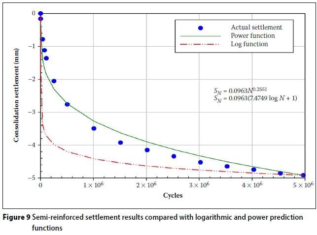
The actual settlement results for each test were also modelled with the relationships described in Equations 2 and 3. The actual settlement data was compared to power and logarithmic functions. The results from these comparisons for the semi-reinforced ballast test are shown in Figure 9 (consolidation phase) and Figure 10 (combined initial and consolidation phase).
The coefficient of correlation values (R2) for the power functions used to theoretically predict the total settlement of each test were significantly lower than the R2 values for the logarithmic prediction functions. For the total settlement R2values, the power functions were not adequate and the logarithmic prediction function gave better correlation. The lowest R2value for the total settlement logarithmic prediction functions was 0.77, and for the same test the R2 value for the power function was 0.22. A summary of these results is provided in Table 4.
From these results, and from those in the previous section, it would appear that when there is significant initial settlement in the early load cycles (such as in uncompacted ballast), the logarithmic prediction function would be the ideal relationship to use, as it provides the closest estimate in these cases. For test samples where initial settlement is not that significant, the power function tended to provide superior results. For this reason, the prediction function chosen should be selected based on the present testing conditions and behaviour of the test sample.
Ballast layer resilient modulus
The ballast layer resilient modulus (Er) was calculated by dividing the applied ballast stress by the ballast layer strain for that cycle. The stress directly below the sleeper was approximately 390 kPa, assuming a sleeper area of 2 200 mm x 300 mm and a load of 260 kN. The ballast layer resilient modulus results can be seen in Figure 11. The unreinforced ballast layer had the highest initial modulus, with a modulus of 184 MPa. The resilient modulus of the unreinforced ballast layer increased up until 500 000 cycles, after which a gradual decrease in stiffness can be observed, most likely as a result of ballast breakdown, causing the ballast layer to become fouled and leading to a loss in strength.
The partially reinforced ballast layer (50% reinforcement) showed an increase in modulus throughout the duration of the test. The other two fully reinforced ballast tests showed lower initial moduli than the partially reinforced and unreinforced ballast tests. The 50% reinforced ballast sample commenced with an initial modulus of 121 MPa and this increased to 186 MPa during the course of the test. At the end of the test, the 50% reinforced ballast sample had a modulus that was approximately equal to that of the unreinforced ballast sample (186 MPa vs 189 MPa respectively).
The completely reinforced ballast sample that had the polyurethane foam expansion limited, achieved a 41% increase in resilient modulus during the course of the test. Even the test where the polyurethane foam reinforcement was allowed to freely expand (which performed very poorly with regard to settlement) achieved a 72% increase in modulus over the course of the test.
In the case of the fully reinforced ballast, the resilient modulus of the layer gradually increased with the increase in load cycles. This increase in modulus could be as a result of the small foam-filled gaps between the ballast stones becoming fully compressed, allowing the ballast stones to regain contact with one another. The final modulus values of the fully reinforced ballast layers were found to be significantly lower than those of the unreinforced and 50% reinforced ballast layers. Interestingly, the unreinforced ballast layer modulus values of the first and final loading cycles showed only a 2.8% difference, whereas all the reinforced ballast samples showed significant modulus gains of at least 40% (fully reinforced expansion) to 72%, as in the case of the fully reinforced ballast layer with unlimited foam expansion.
Ballast breakdown
The ballast breakage index was calculated for the unreinforced and partially reinforced tests. In Figure 12 it can be seen that the grading of the partially reinforced ballast sample falls outside the theoretical maximum ballast breakage line. This could be as a result of the significantly thinner ballast layer, which had a depth of 150 mm. The fact that the ballast below this thin layer was reinforced with a rigid polyurethane foam could also have played a role in the ballast breakage behaviour.
The partially reinforced ballast layer had a BBI of 3.3%, and the unreinforced ballast layer had a BBI of 3.8%, indicating that there was no significant difference in ballast breakage between the partially reinforced and unreinforced ballast tests.
Testing frequency comparison
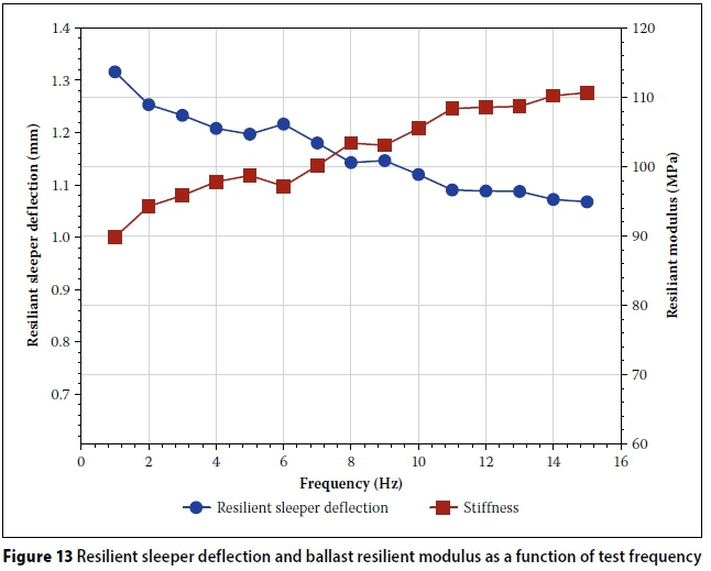
A test was conducted in which the 260 kN cyclic load was applied across a range of frequencies from 1 Hz to 15 Hz at 1 Hz increments. At each frequency, a constant testing time (60 seconds) was applied, resulting in a variation in the number of cycles from 60 to 900 for the 1 Hz to 15 Hz frequency range.
The effect of the change in frequency was examined by comparing the sleeper deflection and settlement per cycle. An increase in the resilient modulus of the ballast samples of 22% was observed over the frequency range (1 Hz to 15 Hz). The resilient deformation and resultant ballast resilient modulus trends as a function of testing frequency are shown in Figure 13.
CONCLUSIONS
The following main conclusions were reached during the course of this study:
■ The use of rigid polyurethane foam as ballast reinforcement is suitable for reducing settlement in track structures. The significant reduction in total settlement of ballast layers reinforced with rigid polyurethane foam could result in better long-term track geometry stability. As a result, a longer track life cycle can be expected when using rigid polyurethane foam as ballast reinforcement.
■ Rigid polyurethane foam-reinforced ballast settled 60% less than conventional unreinforced ballast, and reinforcing only 50% of a ballast layer led to a reduction in settlement of 42% compared to that of conventional unreinforced ballast.
■ In the case of rigid polyurethane foam-reinforced ballast, the ballast resilient modulus (Er) increased as the number of cycles increased (25% increase in modulus for the 50% reinforced ballast layer) and 20% increase for the layer that was fully reinforced with foam expansion limited. This increase in ballast resilient modulus with time could be used to aid engineers in the design of track transitions or as a solution to problem track transition sections.
■ The power and logarithmic function settlement prediction equations can be used for predicting the settlement of reinforced ballast samples. Theoretical logarithmic prediction functions were more suitable for predicting settlements in tests with large initial settlement.
In contrast to this, power functions provided a more suitable method for predicting settlement tests with small initial settlement values.
■ The effect of different test frequencies on the behaviour of the ballast with regard to sleeper deflection per loading cycle, and the resulting ballast resilient modulus in the range of 1 Hz to 15 Hz were investigated. An increase in the resilient modulus of the ballast samples of 22% was observed over the 1 Hz to 15 Hz frequency range.
In conclusion, the use of rigid polyurethane foam as a means of reinforcing railway ballast has numerous benefits. A reduction in total settlement was achieved. The composite rigid polyurethane foam and ballast material produced a layer that resulted in a structure that decreased the resilient sleeper deflection and increased the ballast resilient modulus values, with an increase in load applications. The behaviour of the foam and foam/ballast composite material was quantified, and the settlement and load deflection behaviour of unreinforced and reinforced ballast was characterised.
ACKNOWLEDGEMENTS
Transnet Freight Rail is gratefully acknowledged for financial support to the Chair in Railway Engineering at the University of Pretoria. The authors also wish to thank Mr Johan Scholtz and Mr Derek Mostert of the Department of Civil Engineering at the University of Pretoria for their assistance with the laboratory tests, specialised equipment and writing of this paper.
REFERENCES
AREMA (American Railway Engineering and Maintenance-of-Way Association) 2010. AREMA Manual of Railway Engineering. Lanham, MD: AREMA. [ Links ]
Esveld, C 2001. Modern Railway Track. 2nd ed. Zaltbommel, Netherlands: MRT Publications. [ Links ]
Indraratna, B, Ionescu, D, Christie, D & Chowdhury, R 1997. Compression and degradation of railway ballast under one-dimensional loading. Australian Geomechanics, 32(December): 48-61. [ Links ]
Indraratna, B, Lackenby, J & Christie, J 2005. Effect of confining pressure on the degradation of ballast under cyclic loading. Geotechnique, 55(4): 325-328. [ Links ]
Keene, A K, Edil, T B, Tinjum, J M & Brown, R W 2012a. Characterization of polyurethane-stabilized ballast. Paper presented at the 3rd International Conference on New Developments in Soil Mechanics and Geotechnical Engineering, Nicosia, North Cyprus. [ Links ]
Keene, A, Tinjum, J, Tuncer, E & Brown, R 2012b. Railway substructure stabilization with polyurethane injections. Paper presented at the Mid-Continent Transportation Research Forum 2012, 6-7 September 2012, Madison, WI. [ Links ]
Keene, A, Tuncer, E, Fratta, D & Tinjum, J 2013. Modeling the effect of polyurethane stabilization on rail track response. Proceedings, Geo-Congress 2013, 3-7 March 2013, San Diego, CA. [ Links ]
Nicks, J 2009. The bump at the end of the railway bridge. PhD thesis, College Station, TX: Texas A&M University. [ Links ]
Read, D & Li, D 2006. Design of track transitions. Transportation Research Cooperative Program: Research Results Digest, 79(October): 1-36. [ Links ]
Sasaoka, C & Davis, D 2005. Implementing track transition solutions for heavy axle load service. Proceedings, AREMA Annual Conference, 25-28 September 2005, Chicago, IL. [ Links ]
Selig, E T & Waters, J M 1994. Track Geotechnology and Substructure Management, 1st ed. London: Thomas Telford Publications. [ Links ]
Shenton, M J 1974. Deformation of railway ballast under repeated loading conditions. In: Kerr, A D (Ed.), Railroad Track Mechanics and Technology, 1st ed. Proceedings of a Symposium held at Princeton University, NJ, 21-23 April 1975. [ Links ]
Woodward, P, Kennedy, J & Medero, G 2009. Three-dimensional track reinforcement using polymer geocomposites. Proceedings, Annual Convention of the American Railway Engineering and Maintenance-of-Way Association (AREMA), Chicago, IL. [ Links ]
 Correspondence:
R F du Plooy
Transnet Freight Rail Chair in Railway Engineering
Department of Civil Engineering
University of Pretoria
Pretoria 0001
South Africa
T: +27 83 288 7669
E: rudidu@gmail.com
P J Gräbe
Transnet Freight Rail Chair in Railway Engineering
Department of Civil Engineering
University of Pretoria
Pretoria 0001
South Africa
T: +27 12 420 4723
E: hannes.grabe@up.ac.za

RUDOLPH DU PLOOY obtained a BEng degree in Civil Engineering from the University of Pretoria. He followed that up with a BEng (Hons) in Transportation Engineering in 2014 and an MEng (Transportation) in 2016, also from the University of Pretoria.

PROF HANNES GRÄBE (Pr Eng, FSAICE) is a civil engineer with experience in the fields of track technology, geotechnology, advanced laboratory testing, field investigations, maintenance models and numerical analysis of track structures. He is Associate Professor: Transnet Freight Rail Chair in Railway Engineering atthe University of Pretoria, where he lectures under- and post-graduate courses in railway engineering. He is also responsible for railway research, as well as continuing professional development (CPD) in the form of short courses presented to industry.

