


Services on Demand
Article
 English (pdf)
 Article in xml format
 Article references
Indicators

Related links
-
 Cited by Google
 -
 Similars in Google
Share

 Permalink
Journal of the South African Institution of Civil Engineering
On-line version ISSN 2309-8775
Print version ISSN 1021-2019
J. S. Afr. Inst. Civ. Eng. vol.58 n.3 Midrand Sep. 2016
http://dx.doi.org/10.17159/2309-8775/2016/v58n3a2
TECHNICAL PAPER
Modelling of a lateral load test on piles using simplified and numerical methods
D Raddatz; O Taiba
ABSTRACT
The main purpose of this study was to model the response of piles during a lateral load test conducted at RPC in Concón in 2006 by using simplified theoretical methods and the software Plaxis 2D, Cype, and GGU-Latpile. The piles were the longest built in Chile at the time of the test. This article contains the test description, a geotechnical characterisation and the theoretical fundamentals that support the different methods used for modelling the test. The results of the different models are also presented here. It is concluded that results obtained by simplified methods may be efficient in the early stages of a project and that accurate approximations can be achieved by using design software for continuous elements in the design of isolated elements.
Keywords: pile, lateral load test, test modelling, finite element method, load-displacement relationship
INTRODUCTION
Piles are a type of foundation capable of transmitting loads from the upper structure to the ground at depth. They are used when surface soil is unsuitable for shallow foundations (Das 1999). Pile foundations are frequently used in order to resist lateral loads (Weaver et al 1998). The lateral loads that can be produced by earthquakes, ground pressure, waves and/ or wind must be considered in the design of piles (Candogan 2009). The tests performed in previous studies have validated that foundation piles can withstand lateral loads through shear loads, bending moments, and lateral resistance of the ground (Bowles 1996). The failure mode in free-head piles, as the tested piles, depends on the pile length, rigidity of the section and the load-deformation relationship of the ground (Broms 1964). A soil-pile system can be modelled to find the deformations and internal stresses considering external forces acting on the piles, their geometrical and physical characteristics, and the soil properties. Two simplified soil-pile interaction methods are described in this article - the Semi-Infinite Beam method and the Kocsis method. The software calculation method of Plaxis 2D, Cype and GGU-Latpile are explained here. These simplified methods and software were used to model a lateral load test conducted at Refinería de Petróleo de Concón (Concón Oil Refinery) on the longest piles built in Chile at that time.
GEOTECHNICAL CHARACTERISATION
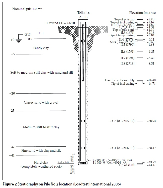
The soil mechanics report of the project (Petersen 2002) contains the stratigraphy and soil properties where a Coker plant is located in the Concón Refinery. In addition, the considerations for foundation design and the characteristics that the compacted structural fill must have are indicated. Also, a drilling stratigraphic record was performed for each of the test piles (Loadtest International 2006). From the geotechnical report (Petersen 2002), the average natural ground level is at elevation +4.00. In the first 35 m, there is a soft, organic and normally consolidated clay, with medium to high plasticity, a dark-grey to black colour, and an SPT value of 4 to 6. Secondly, a soil horizon of about 7 m of soft, organic, high plastic black clay is present, with an SPT value of 9 to 12. At a depth of 42 m below surface, a hard soil strata of plastic and sedimentary clay with high consistency and gravel is present, with an SPT value of 21 to 42. Finally, from a depth of 46 m basement rock is encountered. The geotechnical report also provides a constant value for the modulus of sub-grade reaction of Khstatic = 4 000 KN/ m3, which value corresponds with the soft layer of clay. The same document states that a compacted structural fill will be used on the first 4.2 m from the surface. The filler material to be used must be gravelly sand and/or sandy gravel. The water table position is 4.7 m below the surface. Figures 1 and 2 show the geotechnical characterisation obtained during the drilling of piles No 1 and No 2 respectively.
DESCRIPTION OF THE PERFORMED TEST
During February 2006 integrity and performance tests were conducted. These tests were carried out by the company Pilotes Terratest S A and Loadtest International Inc in two piles built for this purpose. The tests have been performed on piles of 1 200 mm diameter and 50 m long. A lateral load test was included.
The main objective of the lateral load test, for which these two piles were used, was to obtain the real displacement recorded over the top of the piles when being subjected to a horizontal load, and to find a lateral displacement-depth curve by using installed inclinometers, in order to verify the design (Pilotes Terrastest 2006a). The maximum test load was 1 040 KN, which was reached through load steps. The schematic representation of the test is shown in Figure 3.
Instrumentation measured deformation at the pile head and displacement with depth (Pilotes Terratest 2006b). This instrumentation can be described as follows:
■ Two dial gauges, which were located on each pile, registered the deformation at the pile head for each level of applied load. These dials were placed in an installed beam.
■ An inclinometer with strain gauges was located inside the piles. The sensors digitally collect the displacement for each load level based on the differences of inclination angles (Sanhueza & Oteo 2009). The inclinometer pipes were installed along with the piles. Lateral displacement readings were performed in the first 20.0 m on both piles.
Two piles, separated by a distance of 54 m, were used in the test - one as a reaction of the other. Loading on pile No 1 was performed by an ultralight hydraulic jack, and a 12-wire anchor was used as load transfer mechanism on pile No 2 (see Figure 4).
SOIL-PILE INTERACTION METHODS
The theory of soil-pile interaction methods is explained in this section - firstly the semi-infinite beam method, and secondly the Kocsis method. In both these methods the behaviour of the pile under lateral load and/or moment can be modelled (Orostiga 1991). Unlike other soil-pile interaction methods - which allow using different moduli of subgrade reaction values along the pile, such as the Gleser method (Gleser 1984) - the two chosen methods only require using one constant modulus of subgrade reaction along the complete pile length. It was decided to use simplified theoretical methods with a constant modulus, so that modelling of the test features a wider range in the complexity, which means simple theoretical models on the one hand and more complex analysis software on the other. This allows having tools for the different stages of a project, depending on the complexity of the required analysis. For instance, for complex methods high quality and quantity of data is required (Siddharthan & El-Gamal 1996). This data is difficult to obtain in preliminary design.
Semi-infinite beam method
The displacement (y), slope (θ) or internal stresses in the pile can be evaluated with this method (Ortigosa 1991), in which a semi-infinite beam is considered simulating the pile interacting with the soil. This analysis requires solution of the differential Equation 1 relating moment to displacement.
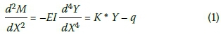
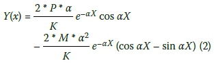
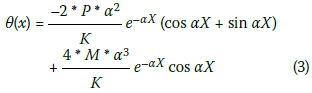
where E is modulus of elasticity, I is moment of inertia and K is product between Kh and D, where Kh corresponds to the horizontal modulus of subgrade and D to the beam width. The hypotheses used in this method are constant Kh and constant section with no axial forces being considered. Equations 2 and 3 are obtained for a pile with a point load P and a moment M in the pile head (X > 0):
Kocsis method
Equations along the pile for displacement, slope and internal stresses are derived from integration of the equation of the reaction pressure of the soil (Kocsis in Orostiga 1991). This pressure is obtained using the equation of displacement of an idealised pile: PR = Kh * δ, where PR is pressure, Kh is modulus of subgrade reaction, and δ is horizontal deformation. The length of the idealised pile is obtained with the equation of the work produced by the load H moving a displacement Δ; this equation is derived with respect to L in order to find the length that minimises the deformation energy. X is measured from the ground surface to depth, and the displacement curve corresponding to a pile with a free head and a displacement Δ in the pile head is used as follows:
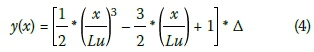
The length Lu corresponds to the depth where after deformations are negligible, and X is the depth. To calculate Lu, the resultant of the pressure exerted by the soil is found, which is separated in the reactions at the pile head (R7ë) and at the pile base. The externally acting load (H) and two reactions are present in the pile head - the first reaction is produced as a result of the pressure exerted by the ground (RTe) and the second reaction is due to the shear force (V) which is generated by imposing a deformation Δ:
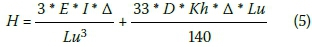
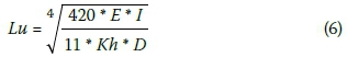
If a beam is gradually loaded to value H, so that the end deformation is Δ, the expression for the work can be obtained, which is derived with respect to the length. For solving Lu, the following expression is obtained:
Knowing the expression for Lu, the applied load can be rewritten as:

The equation that describes the pressure exerted by the soil on the pile is:
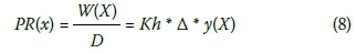
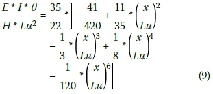
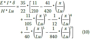
Solving Δ from the Equation 7 and inserting it in Equation 8, the expression for the pressure exerted by the soil is obtained. Using the theory of material strength, integrating and applying boundary conditions, the following expressions are obtained for both the slope θ (Equation 9) and displacement δ (Equation 10):
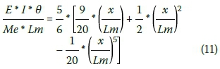
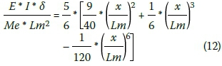
In the case of a free head and moment, the analysis is analogous to the previous case. The following expressions are obtained for the slope (Equation 11) and deformation (Equation 12):
Method for extended pile
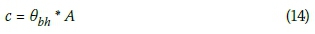
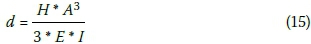
This section shows the analysis required to model the pile length located above ground level. This method is described in Orostiga (1991). At the point where the load is applied, deformation can be expressed as:
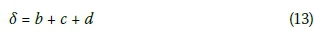
where b is deformation at ground level, c is deformation by the slope at ground level, and d is free deformation due to applied load H.
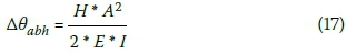
In addition, the following expression may be derived for the slope at the same point:
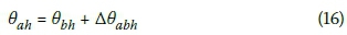
where θbhis slope at the ground level, and Δθabhis slope after application of load H.
Sensitivity to variation in Kh
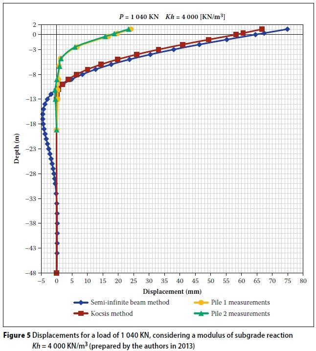
The expressions described in the previous sections were evaluated in order to model the lateral load test. As shown in Figure 5, using the Kh = 4 000 KN/m3 value (modulus of subgrade reaction) indicated in the geo-technical report (Petersen 2002) for the clay strata, the displacements obtained with the theoretical models are significantly higher than those measured in the field test for the maximum load.
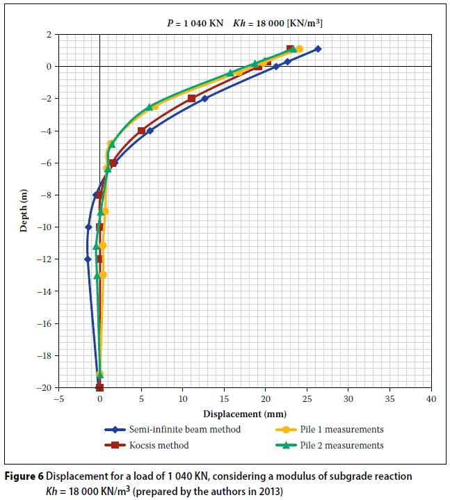
In order to calibrate the theoretical model with the measurements taken on site, a sensitivity analysis was performed. Since the geometry and the physical properties of the pile do not have the level of uncertainty that the soil properties have in this case, the sensitivity analysis was conducted varying the value of modulus of subgrade reaction Kh. By trialing various values, the value of Kh = 18 000 KN/m3 was finally adopted as characteristic for the entire length of the pile. This value is higher than that indicated for the clay soil layer in the geotechnical report (Petersen 2002). It is believed it reflects the greater rigidity of the granular fill and the fixity in the rock at depth. As shown in Figure 6, similar values of displacements for the maximum test load of 1 040 KN were obtained if this value of Kh is used.
SOFTWARE
Cype
To model the horizontally loaded pile, the software Muros Pantallas (Retaining Walls) from Cype was used. The analysis method and parameters needed for modelling using this software are discussed in this section. The calculation model used to obtain the stresses and displacements of the wall is based on the methods of ground-wall interaction, where the magnitude of the earth pressures on the wall depends on its displacement (Cype Ingenieros S A 2013a). For the calculation of the action and/or reaction produced by the soil on the wall, elastoplastic behaviour is considered. The linear range of behaviour is associated with the concept of the lateral modulus reaction of the soil, and the plastic range with the concept of active or passive earth pressure according to the displacement direction. The passive earth pressure is calculated by evaluating the Jaky formula (Cype Ingenieros S A 2013b). The active and passive pressures are calculated using the Coulomb theory.
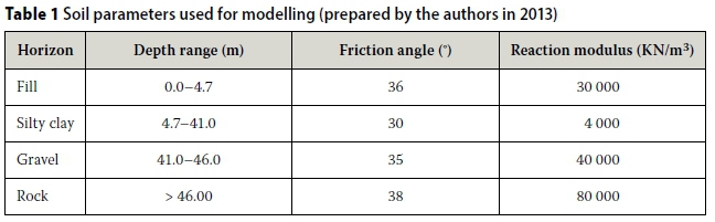
A wall with an inertia equivalent to that of the pile was considered for modelling the pile. The wall was sized with a horizontal load and a moment applied to the top. With this, a load equivalent to the one of the test is achieved, since the load on the test was applied at a certain distance from the surface. Four soil horizons were defined to characterise the soil. Table 1 shows some parameters used to model the test. Ten different stages with the different test loads were defined. To obtain an equivalent load to the test load, it was necessary to input the actual test load divided by the width of the modelled wall, because the loads are entered into the program per linear metre.
GGU-Latpile
The method used in the software GGU-Latpile is described in this section. The model used to obtain the stresses and displacements is based on an elastic analysis considering the soil stress, determined by the product of the reaction and the deformation along the pile length (Buß 2012). This elastic stress must not exceed the passive earth pressure that can develop at the front of the pile. The norm option DIN 4085 (DIN 1987)
was chosen for the active earth pressure. For the passive earth pressure, the Streck option was chosen, in which the coefficient of passive earth pressure is found by interpolating from a table (Weissenbach et al 2003). The pile used in the test was the one chosen to model the pile. The same soil properties used in the modelling performed in the Cype software were used for this model. Ten different stages with the test loads were defined by entering the real test load and a moment at the top of the pile, equal to the applied load multiplied by the application height, 0.3 m.
Plaxis 2D
The analysis performed using the finite element model Plaxis 2D is explained in this section. The operation of the program and the parameters needed for modelling are also indicated here. Plaxis 2D is a two-dimensional software of finite elements, designed to solve geotechnical problems. It has two options to model two-dimensional problems - plane strain and axisymmetric. Triangular elements of 6 or 15 nodes may be selected to model soil and other materials. Interface elements are used to simulate the interaction between the soil and the structure (Brinkgreve 2004).
Different options can be used for modelling materials. The linear elastic model is linear and isotropic, and it relates the stress and the unitary deformation through Hooke's law of isotropic linear elasticity. It is necessary to have two elastic stiffness parameters - the Young's modulus (E) and Poisson's ratio (ν) (Brinkgreve 2004). This model is mainly used for modelling rigid structural elements (Abbas et al 2008) as the piles in the ground of this case. To model the soil, the hardening soil model can be used, which is an advanced second-order model (Brinkgreve 2004). It corresponds to an elastoplastic variant of the hyperbolic model, formulated in the context of hardening plasticity. The parameters required for modelling the soil behaviour with this model are (Plaxis 2004): cohesion (c), friction angle (φ), dilatancy angle (ψ), triaxial loading stiffness (E50), oedometer load stiffness (Eoed), triaxial unload stiffness (Eur), the dependence of soil stiffness with the stress levels (m), Poisson's ratio for unload/reload (vur), rigidity coefficient (pref), coefficient of lateral stress at rest (K0nc) and the ratio between failure and ultimate stress (Rf).The following can be considered as approximate values (Plaxis 2004):
A plane strain model was used to model the pile, using elements with 15 nodes to achieve a greater precision in the analysis. Although geometrically a pile is better represented by an axisymmetric shape, since in this case the load is applied in a single radial direction, it was not possible to use this model. A wall with an inertia equivalent to the pile, 1 m wide, was considered. This width was chosen in order to work in units per metre. The wall was sized at 0.3 m on the surface. The load was applied at the top, simulating the application point in the performed test. Hence, the value of the horizontal force in the pattern corresponds to the same one of the test.
To characterise the ground on which the test was conducted, the four soil horizons previously described were modelled. Soil parameters were considered according to the properties described in the geotechni-cal report of soil mechanics, and the soil stiffness parameters were varied until deformation values similar to the ones measured in the test were attained (refer to Table 2). The stiffness values finally used have approximately the same magnitude as those used in other studies (Molina et al 2007).
RESULTS
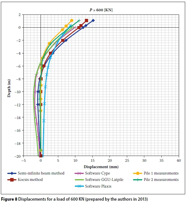
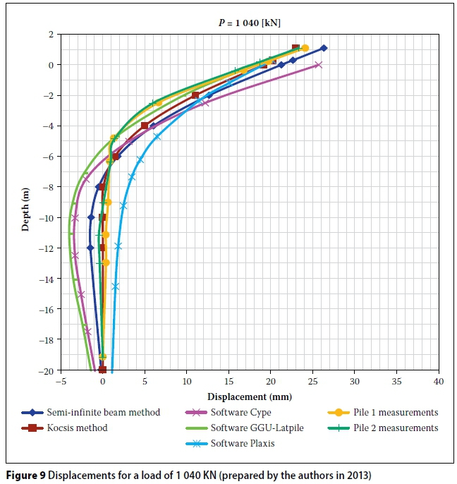
Three representative load steps were selected - 200 KN, 600 KN and 1 040 KN. Figures 7, 8 and 9 detail the results.
The results obtained using Cype and GGU-Latpile are similar to the measured values in the first load steps. For the higher loads, both models show a similar shape, especially from a depth of 5 m. The results obtained through the model made in Plaxis 2D for the displacement curve versus depth, are the closest to those measured, except for the highest loads, where the results from the Kocsis model are closest to the field measurements. Results obtained by the Plaxis 2D and Kocsis methods do not represent negative displacements along the curve. This relates quite accurately to the information recorded in the test, in which the negative measurements are small and insignificant. From the analysis using Plaxis 2D, the best deformation results are achieved at the head of the pile for all load steps.
CONCLUSIONS
Pile behaviour testing is an important aspect to consider in the design of piles. It is clear that test results can help to reduce costs, decreasing oversizing by reducing the uncertainty of pile behaviour. It also allows adjustments to the design in order to reach the expected behaviour of the system. From this study, it is concluded that the Kocsis method, with a coefficient of Kh = 18 -000 KN/m3, results in displacement similar to those measured in the tests for the highest loads. The value adopted is significantly higher than that indicated in the geotechnical report. This is mainly due to the fact that in reality there is a compact granular fill layer near the surface, which provides a high horizontal stiffness to the system.
In the analysis performed using the finite element software, Plaxis 2D, displacement versus depth results very similar to those tested were achieved, especially for the mid and low loads. The best results on the head were achieved with this software, for all load steps. The Plaxis 2D software allows the use of more parameters, as well as providing a more complex method to study the deformation of the soil surrounding the pile. This result was as expected.
During high load stages, the Kocsis model presents results that are closer to those measured, especially when no negative deformation resulted. The results obtained by the beam-on-elastic-foundation method were similar to those recorded in the tests. While both methods sufficiently simplify the problem, good results can be achieved after a review of the soil characteristics defined in the investigation.
Notwithstanding that the piles are isolated elements, fair approximations to the test results are obtained through the use of software with models for continuous elements, such as Cype and Plaxis 2D.
From the analysis conducted with the different models, a high sensitivity of the lateral displacements to the input values of horizontal stiffness of the soil is deduced, using Kh in the simplified methods and in the software Cype and GGU-Latpile, or through the stiffness parameters required for soil modelling in Plaxis 2D. This is the most important parameter to obtain correct characterisation of the behaviour of an element in contact with the ground when it is loaded laterally. It is essential to conduct a thorough review of the available geotechni-cal data to adequately represent the ground in which modelling is intended. It is recommended that more than one tool be used to compare the results when modelling these types of problems.
ACKNOWLEDGEMENT
We thank the company Pilotes Terratest S A for providing all the background information used in this paper.
REFERENCES
Abbas, J, Chik, Z & Taha, M 2008. Single pile simulation and analysis subjected to lateral load. Electronic Journal of Geotechnical Engineering, 13(E): 1-15. [ Links ]
Bowles, J E 1996. Foundation Design and Analysis. Singapore: McGraw-Hill. [ Links ]
Broms, B B 1964. Lateral resistance of piles in cohesive soils. Journal of the Soil Mechanics and Foundations Division, 90(SM2): 27-63. [ Links ]
Brinkgreve, R B J 2004. PLAXIS 2D Reference Manual. Delft, Netherlands: Delft University of Technology & Plaxis BV. [ Links ]
Buß, J 2012. GGU-Latpile: User manual. Steinfeld, Germany. [ Links ]
Candogan, A 2009. The Art and Practice of Foundation Engineering. Istanbul, Turkey: Ali Candogan. [ Links ]
Cype Ingenieros SA 2013a. Muros Pantallas: Manual del Usuario. Alicante, Spain. [ Links ]
Cype Ingenieros SA 2013b. Elementos de Contención: Cálculo de Empujes. Alicante, Spain. [ Links ]
Das, B M 1999. Fundamentals of Geotechnical Engineering, 4th ed. New York: Thomson Engineering. [ Links ]
DIN (Deutsches Institut für Normung) 1987. DIN 4085: Calculation of Earth-pressure. Berlin, Germany: DIN. [ Links ]
Gleser, S M 1984. Generalized behavior of laterally loaded vertical piles. In: ASTM. Laterally Loaded Deep Foundations: Analysis and Performance. Baltimore, MD: ASTM, pp 72-96. [ Links ]
Load Test International Inc. 2006. Letter re lateral transmittal. Port Elizabeth: Load Test International Inc. [ Links ]
Molina, D, Rivero, P & Lobo, W 2007. El nivel freático como modificador de las respuestas espectrales de aceleración, velocidad y desplazamiento (The phreatic level as spectral response modificator of acceleration, velocity and displacement). IMME, 45(1): 53-71. Available at: http://www.scielo.org.ve [ Links ]
Orostiga, J 1991. Análisis de pilotes cargados lateralmente (Analysis of lateral test loads). Professional degree thesis. Available from UTFSM Library, Valparaiso, Chile. [ Links ]
Petersen, M 2002. Informe de mecánica de suelos proyecto Planta Coker. Valparaiso, Chile: Miguel Petersen. [ Links ]
Pilotes Terratest 2006a. Informe final de ensayos efectuados sobrepilotes #1 y #2. Santiago, Chile. [ Links ]
Pilotes Terratest 2006b. Memoria descriptiva ensayos de aceptación a carga lateral pilote 1 200 mm. Santiago, Chile. [ Links ]
Pilotes Terratest 2006c. Resumen Fotos Ensayos RPC. Santiago, Chile. [ Links ]
Plaxis, BV 2004. Materials models manual. Delft, Netherlands: Delft University of Technology & Plaxis BV. [ Links ]
Sanhueza, C & Oteo, C 2009. Control de movimientos reales producidos en pantallas continuas en Madrid (Control of actual movements during continuous screens in Madrid). Revista De La Construcción, 8(2): 72-84. [ Links ]
Siddharthan, R V & El-Gamal, M 1996. Earthquake-induced ground settlements of bridge abutment fills. In: Prakash S (Ed.), Analysis and Design of Retaining Structures against Earthquakes. New York: ASCE, pp 100-123. [ Links ]
Weaver, T J, Rollins, K M & Peterson, K T 1998. Lateral statnamic load testing and analysis of a pile group. In: Dakoulas P, Mishac ,Y & Holtz, R D (Eds.). Geotechnical Earthquake Engineering and Soil Dynamics III, Vol. 2. Reston, VA: ASCE, pp 1319-1330. [ Links ]
Weissenbach, A, Hettler, A & Simpson, B 2003. Stability of excavations. In: Smoltczyk, U (Ed.). Geotechnical Engineering Handbook, Vol. 3: Elements and Structures. Berlin, Germany: Ernst & Sohn, pp 273-407. [ Links ]
 Correspondence:
D Raddatz
Rengo 1270 Nunoa Santiago
Chile 7770112
T: +56 2 22041010
E: dennis.raddatz@ferrara.cl
O Taiba
Rengo 1270
Nunoa Santiago
Chile 7770112
T: +56 2 22041010
E: oscartaiba@ferrara.cl

DENNIS RADDATZ obtained a Professional degree in Civil Engineering at Federico Santa Maria University in Chile, and a Master's in Geotechnical Engineering at the University of Massachusetts Amherst in the United States of America. His work experience has focused on geotechnical characterisation, and design of foundations and soil retaining structures. His research interests also include computational modelling, soil behaviour and soil-structure interaction. He currently works for the Chilean company Ferrara-Proyectos Especiales, and was previously in the employ of the company Pilotes Terratest.

OSCAR TAIBA, who has a Master's in Soil Mechanics, obtained his degree in Civil Engineering at Federico Santa Maria University in Chile. He has more than 15 years of experience in geotechnical engineering, focusing on soil improvement, numerical modelling, geotechnical characterisation, design ofretaining structures for deep excavations, and design of pile foundations and diaphragm walls. Currently he is a project manager for the company Ferrara-Proyectos Especiales, and also lectures at Federico Santa Maria University. He has supervised more than 20 Master's and Professional degree theses.

