Services on Demand
Article
Indicators
Related links
-
 Cited by Google
 -
 Similars in Google
Share
Journal of the South African Institution of Civil Engineering
On-line version ISSN 2309-8775
Print version ISSN 1021-2019
J. S. Afr. Inst. Civ. Eng. vol.58 n.2 Midrand Jun. 2016
http://dx.doi.org/10.17159/2309-8775/2016/v58n2a1
TECHNICAL PAPER
Development of a practical methodology for the analysis of gravity dams using the non-linear finite element method
J H Durieux; B W J van Rensburg
ABSTRACT
For many decades the 'classical' method has been used to design gravity dams. This method is based on the Bernoulli shallow beam theory. The finite element method (FEM) has become a powerful tool for the dam design engineer. The FEM can deal with material properties, temperatures and dynamic load conditions, which the classical method cannot analyse. The FEM facilitates the design and optimisation of new dams and the back analysis of existing dams.
However, the linear elastic FEM has a limitation in that computed stresses are sensitive to mesh density at 'singularity points'. Various methods have been proposed to deal with this problem. In this paper the Drucker-Prager non-linear finite element method (DP NL FEM) yield model is presented as a method to overcome the problem of the stress peaks at singularity points, and to produce more realistic stresses at the base of the dam wall.
The fundamentals of the DP NL FEM are presented. Benchmark studies of this method demonstrate the method's viability to deal with zones in a structure with stresses beyond the elastic limit where yielding of the material occurs.
A case study of a completed gravity dam is analysed, comparing several analysis techniques. The service and extreme load cases are investigated. Different material properties for the concrete and rock, including weathered material along the base of the wall, are considered. The application and merits of the DP NL FEM are presented. The calculation of the critical factor of safety against sliding is done with a more realistic determination of the conditions along the base of the wall.
Keywords: gravity dams, non-linear finite element method, classical method, singularity point, Drucker-Prager
INTRODUCTION
Throughout history many methods and theories have been developed to design gravity dams. For many decades the popular 'classical' or 'conventional' method (CM) was used. This method became virtually a design standard and is still used by many engineers. It is based on the formulation of Bernoulli's 'shallow beam theory'. Despite its popularity, the method has many limitations. Its popularity can be attributed to its straightforward approach, conservative results and the fact that manual calculations can be done.
The finite element method (FEM) has become a popular tool for analysing complex structures. Although the geometry of a gravity dam is very basic, the structural analysis of such a mass concrete structure is relatively complex, due to the non-linear material behaviour and the variety of static and dynamic loads acting on the structure. In this paper the FEM is investigated as a design tool for analysing gravity dams. Although the FEM is already widely used for this purpose, there are some deficiencies that have to be addressed in order to fully utilise this method. The major shortcoming of the linear elastic FEM is its sensitivity to mesh density and stress peaks at the points of so-called 'singularities'. These are positions where the structure has sharp edges, or re-entrant corners, usually leading to infinite stresses. An additional shortcoming of the linear elastic FE analysis is dealing with brittle material behaviour in tension and compression stress zones.
Although in this paper the FEM Drucker-Prager material yield model is illustrated with 2-D models, these principles and concepts can also be adapted to 3-D models.
CLASSICAL METHOD (CM)
The theory of the CM is well documented (USBR 1976; CADAM 2001). This method, used to evaluate the stability of a gravity dam, is based on two criteria: (1) the calculation of the tensile stress at the heel and toe of the wall by means of the Bernoulli thin beam formula, and (2) the factor of safety against sliding calculated from the Coulomb friction equation. A set of load combinations is evaluated according to the design standards. These are based on failure mechanisms relevant to the specific gravity dam. The CM method will not be dealt with in this paper, although the results of a CM analysis with the well-known program CADAM (2001) will be illustrated.
In South Africa and many other countries no official code of practice for dam design is available, and the design criteria, load conditions, acceptable stresses and factors of safety (FOS) are left to the discretion of the approved professional person (APP) and/ or design engineers. However, a large variety of SANCOLD (South African National Committee on Large Dams) and ICOLD (International Commission on Large Dams) publications and guidelines are available to the design engineer.
FINITE ELEMENT METHOD (FEM)
The FEM is a powerful design tool for analysing gravity dams, but when the analyses are performed in the linear elastic domain, the problems of stress peaks at the points of singularity have to be addressed. Figure 1 illustrates the singularity problems at the heel and toe of the wall of a gravity dam for a homogeneous wall and foundation. The heel is defined as the position where the upstream face of the wall intersects the foundation face. Similarly the toe is defined as the position where the downstream face of the wall intersects the foundation face.
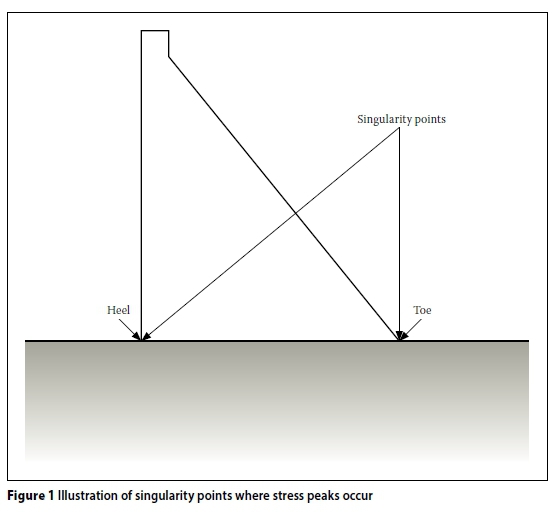
The points where singularities emerge are important positions in gravity dam design. In order to address the singularities problem for linear FE analysis, the following solutions were investigated by Durieux (2009):
■ Identify points where singularities occur and disregard the peak stresses within a small restricted area.
■ Use a relatively coarse FEM mesh to eliminate the singularity effects, but still capture the essential stresses in the wall section with reasonable accuracy.
■ Employ 'stress linearisation'.
■ Modify the geometry to incorporate a fillet or round-off radius, relaxing the stress concentration.
Non-linear analysis techniques provide more realistic stress distributions at singularities:
■ Fracture mechanics techniques which simulate crack development at the singularity point and redistribute the stress surges.
■ Contact elements follow a prescribed path and open when a specified tensile stress occurs, and thus relieve tensile stresses.
■ Non-linear material methods, such as the Mohr-Coulomb and Drucker-Prager yield models, which will be the focus of this paper.
Illustration of the singularity effect on a hypothetical triangular dam in 2-D
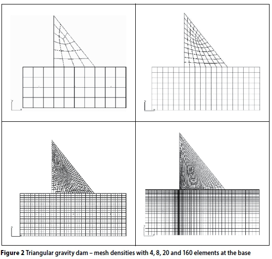
To illustrate the effect of the singularity problem on a gravity dam, a 2-D plane strain FE model of a hypothetical triangular dam was created with different mesh densities. Mesh densities of 4, 8, 12, 20, 40, 80 and 160 elements along the base of the wall were modelled. Figure 2 illustrates some of these mesh densities for a 100 m high triangular gravity dam with a downstream slope of 1:0.8. A monolithically FEM mesh was used, i.e. wall and foundation were only distinguished by their material properties, but no discontinuities were introduced, such as contact elements.
The load conditions applied are: (a) hydro-static pressure of 100 m water applied on the upstream face, (b) full uplift pressure under the wall (triangular distribution from 1 MPa at the heel to zero at the toe), and (c) self-weight of the concrete wall. The MSC Marc FE program was used (MSC Marc 2003).
The material properties of a typical concrete gravity dam were used, i.e. elastic modulus for concrete Ec= 20 GPa, Poisson's ratio ν = 0.22 and density ρ = 2 400 kg/m3. For the foundation, Er= 30 GPa and ν = 0.25 were used. No density was incorporated into the foundation block. The boundary conditions were applied on the foundation block and were fixed on the lower circumference in the x and y directions. The last mesh illustrated in Figure 2 is one-way biased to limit the number of elements, but still has the correct element size at the heel of the wall.
Figure 3 illustrates the contour plot of the vertical normal stress (Sy) for a mesh density of a one-way biased 160 elements at the base of the wall. The load case was for the above-mentioned load condition. The maximum vertical normal stress Syat the heel of the wall is 5.30 MPa.
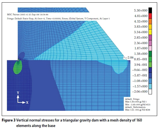
Figure 4 illustrates the distribution of normal tensile stress Syat the heel of the wall for the seven mesh densities. The load conditions (as outlined above) were the same for all the analyses.
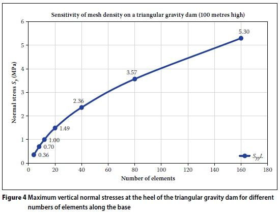
The normal stress Syat the heel of the wall in Figure 4 varies from 0.36 MPa to 5.30 MPa for the 4 to 160 element mesh densities, illustrating the large disparity in the stress. The question is, which stress is the correct one to represent the stress condition at the heel of the wall?
The main stability criterion used in the CM is based on calculating the stress at the heel of the wall and assessing it with an allowable tensile stress for a given load condition. However, when the same evaluation criterion is used with the linear FEM, conflicting conclusions on the safety of the structure can be reached, due to the large stress variation at the heel depending on the mesh density (illustrated in Figure 4). It is thus necessary to adopt another evaluation criterion for the FEM.
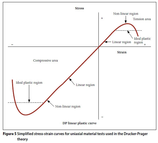
One of the methods mentioned above to address the singularity problem in an FEM is to use the non-linear material yield models. The Drucker-Prager (DP) yield model is well suited to deal with this problem, but then an alternative evaluation criterion would have to be adopted for gravity dams. The authors have found that a useful technique for evaluating the structural behaviour of a gravity wall, utilising the non-linear FEM, is by computing the equivalent plastic strain (EQPS) of the wall for the given load conditions. The EQPS provides a means of measuring the material yielding in the plastic zone (plastic strain) and presents the areas where plastic material yielding is assumed to occur. The EQPS can be illustrated on a graph presenting the normal stress versus strain. The position where the EQPS starts is where the curve deviates from the linear relationship (see Figure 5 in next section).
DETERMINATION OF THE PARAMETERS FOR THE DRUCKER-PRAGER MODEL FROM STANDARD LABORATORY TESTS
The theory of the DP model is well documented in text books, such as Zienkiewicz (1977) and Chen (1982).
A simplified uni-axial stress-strain curve for the DP ideal plastic model is presented in Figure 5, which illustrates the linear and non-linear relationship between stress and strain.
In Figure 5 the stress-strain curve illustrates that the theory of the linear plastic DP (also called the ideal plastic DP) is a conservative approach, because the linear horizontal line of the relationship deviates from the non-linear stress-strain curve when entering the non-linear region. This implies that the yielding stress of the material is kept constant at a lower stress level below the actual stress-strain relationship. This approach is valid only until the horizontal (dotted) line intersects the non-linear curve. The DP analysis should be kept within this strain region to ensure a conservative approach.
Figure 6, from Zienkiewicz (1977), illustrates the Mohr-Coulomb, Tresca, Drucker-Prager (DP) and Von Mises material yield criteria. It should be noted that the stresses are illustrated in the negative zones. The envelopes represent the failure domain. σ2, σ2 and σ3are the maximum, intermediate and minimum principal stresses respectively, φ is the internal friction angle and c the cohesion.
This paper will focus on the Drucker-Prager yield criterion.
Basic theory of the Drucker-Prager model
In Chen (1982) and MSC Marc (2003) the following equation of the Drucker-Prager yield criterion is given:

The equations for calculating the c and φ are given in terms of α and  :
:

where:
c = cohesion of material
Φ = internal friction angle of material
 = calculated yield stress
a = DP constant
J1(MSC Marc 2003) or I1(Chen 1982) is the first invariant of the stress tensor:
J1 = sii with sii = σ1+ σ2+ σ3
σii and σiiare stress tensors

σ1,σ2, σ3are maximum, intermediate and minimum principal stresses respectively.
Chen (1982) gives:

where:

Chen (1982) also gives the equations for determining the values of friction and cohesion in terms of the tensile and compressive yield strength of the material:

where:
ft= tensile strength of material
fc= compressive strength of material
By substituting these values of φ and c in Equation (2) the parameters for the DP model ( and α) can be obtained.
From the above equations it can be seen that, by simply using the tensile and compressive strengths of the concrete, all the necessary parameters for the DP model can be derived. These material properties can be obtained from standard material laboratory tests.
BENCHMARKS APPLYING THE DRUCKER-PRAGER MODEL
To evaluate the accuracy of the DP non-linear FEM (DP NL FEM) to address the singularity problem in concrete structures, a series of benchmarks were conducted.
The DP NL FEM analyses were computed with MSC Marc (2003) using the non-linear material facility. The loads were divided into time-steps and ramped from zero to maximum value during specific time-steps.
The load time-stepping is necessary to accomplish correct convergence in the FE program for material yielding throughout the structure. For each time-step an iterative process was used to ensure that complete convergence had been obtained. Convergence is defined as a solution of which the results for stress or deformation congregate to a single value through the prescribed time-steps and iterations, and the oscillation of the results stabilises within the given convergence tolerances.
The benchmarks from, amongst others, Bhattacharjee and Léger (1994) and Carpinteri et al (1992) were arranged and conducted, and described comprehensively in Durieux (2009), according to the level of complexity:
■ Simple tensile specimen
■ 2-D standard beam test
■ 2-D standard shear beam
■ Model gravity dam
■ Full-size concrete gravity dam.
One benchmark of a model gravity dam (as shown in Figure 7), 2.4 m high, of Carpinteri et al (1992) is summarised by way of illustration. This benchmark was chosen because information on the physical laboratory model and the results of a fracture mechanics study by Bhattacharjee and Léger (1994), same FE model as illustrated in Figure 7, were available.
Bhattacharjee and Léger (1994) analysed this model dam applying a non-linear fracture mechanics crack propagation criterion. A 'fixed crack model with variable shear resistance factor' (FCM-VSRF) was employed. In this model, the local reference axis system is first aligned with the principal strain directions at the instance of softening initiation, and kept non-rotational for the rest of an analysis. The shear resistance factor is derived using the strain components corresponding to the fixed local axis directions. The variable shear resistance factor takes account of deformations in both lateral and normal directions to the fracture plane.
The DP NL FEM was loaded with a triangular load representing the point loads on the model concrete dam. The boundary conditions were applied directly on the base of the wall. No uplift loading was modelled. The total load of the triangularly distributed load was ramped from zero to 1 500 kN. The parameters used in the DP benchmark model are from Bhattacharjee and Léger (1994) and are given in Table 1.

The values for the crack mouth opening displacement (CMOD), for the pre-assigned notch, were computed by the authors utilising the DP NL FEM and the results compared with the experimental data. From Figure 8 it can be seen that the CMOD values compared well with the experimental model. It can be noted that the theoretical fixed-crack model with variable shear resistance factor (FCM-VSRF) is less 'stiff' than the DP NL FEM.
With the maximum load of 1 500 kN, the DP NL FEM model exhibits two zones where plastic strain has occurred, as illustrated by the EQPS, and here material failure can be expected. From the results in Figure 8 it can be seen that the CMOD of the DP NL FEM correlated well with the experimental data of the concrete model by Carpinteri et al (1992).
Models of the DP NL FEM were also prepared by Durieux (2009) to evaluate the sensitivity of peak stresses at singularity points for a variation in mesh density. These results showed that the DP NL FEM is significantly less sensitive (than the linear FEM) to a variation in mesh density.
Finally, to calibrate the mass concrete material parameters for the DP NL FEM, Durieux (2009) studied the laboratory-tested material properties of 12 existing DWS dams. The average tensile strength of the mass concrete used in DWS dams is found to be 3.77 MPa, with a standard deviation of 0.8 MPa. The corresponding compressive strength is 33.3 MPa, with a standard deviation of 12.7 MPa. (This is consistent with the traditionally accepted ratio for mass concrete where the tensile to compression strength ratio is approximately 10%.)
CASE STUDY
The following case study of a dam recently constructed was chosen, because it was designed in accordance with the latest design criteria and reviewed by a panel of specialist dam engineers in South Africa. The dam shape was optimised by the CM in agreement with the recommended design memorandum (RDM) of the Professional Design Team (2005). The objectives of the case study were to illustrate:
■ the contrast in the stress distributions between a linear static analysis and a DP NL FE analysis for an extreme load condition
■ the region where material yielding is expected for an extreme load condition
■ the stress distribution along the base of the wall when a long-term, or residual, material property was used
■ the variation in the factor of safety (FOS) against sliding calculated for the CM and the DP NL FEM, as exhibited by a failure domain graph.
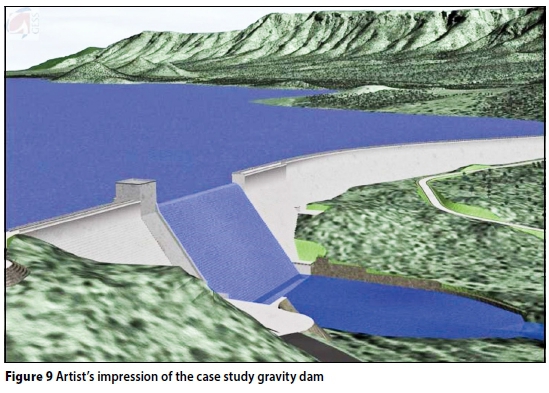
Figure 9 is an artist's impression of the dam. The dam has a centre OG spillway and roller-compacted concrete flanks.
For the purpose of this paper three types of analyses were done for comparison:
■ Classical method
■ Static plane strain linear FEM
■ Static plane strain DP NL FEM.
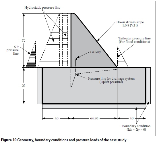
The geometry, boundary conditions and pressure loads are illustrated in Figure 10. Only a static analysis with hydrostatic loads is presented in this paper. The uplift force or pore pressure is for a partial or drained condition.
Classical method
The geometry as presented in Figure 10 was used to set up the data for the CADAM program.
The input parameters for the CM are:
■ Internal friction angle (peak) at the base surface (φ) = 40°
■ Cohesion (peak) at the base surface (c') = 0.6 MPa
■ Density of mass concrete (ρc) = 2 450 kg/m3
■ Density of silt (ρs) = 400 kg/m3
Service load case:
■ Hydrostatic pressure at full supply level (FSL = 75.0 m)
■ Silt load of 40 m
■ Self-weight
■ Partial uplift condition (pore pressure drained under the base line).
Extreme load case:
■ Hydrostatic pressure of a safe evaluation flood (SEF = 81.5 m)
■ Silt pressure of 40 m
■ Tail-water level of 23 m on the down-stream side for an SEF
■ Self-weight
■ Partial uplift condition.
Finite element models
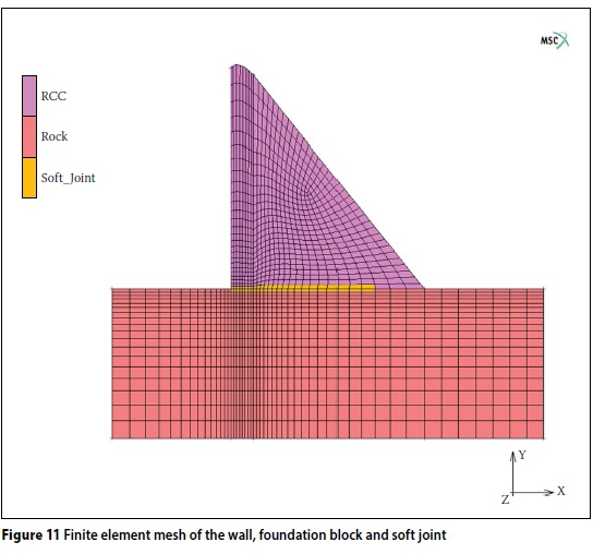
The mesh density for the FEM is illustrated in Figure 11 and is a relatively fine mesh at the heel of the wall. Note the set elements along the base of the wall representing a weak material zone. This is, however not a contact element joint, but a DP material zone.
Assumptions of the finite element models
■ Homogeneous models, i.e. no contact elements
■ No temperature loads
■ No seismic loads
■ Use of second-order isoparametric elements
■ Boundary conditions: The structure was restrained on the foundation block in the x and y directions as illustrated in Figure 10.
The FEM is homogeneous, i.e. no special elements between the wall and foundation were introduced, e.g. contact elements. However, at the first layer of elements above the foundation block a separate material property was also assigned to represent an old and deteriorated contact layer.
The concrete material properties were taken from the Professional Design Team (2007) laboratory report. An average compressive concrete strength of 15 MPa was specified. The maximum allowable tensile stress was determined from the traditional ratio of 1:10 of tensile to compressive stress.
Material parameters
Mass concrete:
■ Modulus of elasticity (Ec) 20 000 MPa
■ Poisson's ratio (υ) 0.22
■ Density (ρ) 2 450 kg/m3
Properties for sliding calculations:
The properties at the base sliding line
■ Friction angle (φ) 40°
■ Cohesion (c') 0.6 MPa
Drucker-Prager parameters:
■ Normal and long-term (residual) compression stress for concrete fcc= 15.0 MPa
■ Normal (residual) tensile stress for concrete ftc= 1.5 MPa
■ Long-term (weathered) tensile stress for concrete frc = 0.2 MPa
The very low residual material strength was chosen to simulate a deteriorated, very old concrete. Results of acoustics emission laboratory tests have demonstrated that old concrete under severe conditions can eventually reach very low tensile strength values of 0.2 MPa (Oosthuizen 2007).
From the equations presented, the values for the DP parameters were calculated:
■ Normal concrete: ftc= 1.5 and fcc= 15 MPa: DP parameters : αtc= 0.247 and
= 2.14 MPa.
■ Deteriorated concrete: ftc= 0.2 and fcc= 15 MPa: DP parameters: atc= 0.283 and
= 0.298 MPa.
Foundation rock properties (for slightly weathered rock):
■ Modulus of elasticity (fractured) (Erock) 10 000 MPa
■ Poisson's ratio (υ) 0.25
■ Density (ρrock) zero
Drucker-Prager parameters for rock:
ft_rock= 1.5 MPa, fc rock= 15 MPa: DP parameters: αrock= 0.247 and  = 2.14 MPa.
Load cases for the linear and non-linear analyses
In order to obtain the correct stresses (for full convergence in the FEM) for the non-linear analysis, the loads were stepped or ramped up through the different steps.
Service load case: time-steps 1 to 3
■ Time-step 1 - the gravity load is ramped from zero to maximum.
■ Time-step 2 - the hydrostatic pressure is ramped from empty to FSL.
■ Time-step 3 - partial or drained uplift pressure is applied, as well as the silt load (silt level = 40 m).
Extreme load case: time-step 4
■ Time-step 4 - The water overspill is ramped from FSL to SEF, and the corresponding tail-water pressure is applied as well (max tail-water = 23 m) (FSL = 75.0 m and SEF = 81.5 m as before).
The factor of safety (FOS) against sliding was determined along the horizontal contact line using the vertical normal stress Syto calculate the Coulomb friction resistance.
DISCUSSION OF CASE STUDY ANALYSES
Classical method
The stresses at the heel and toe were calculated with the CADAM software. The results of the service and extreme load cases are represented in Table 2. The criterion for stability utilising the CM is by evaluating:
■ The tensile stress (with CM compression) at the heel of the wall
■ The compression stress at the toe of the wall
■ The factor of safety (FOS) against sliding. For both the service and extreme load cases no tensile stresses were found at the heel of the wall. This implies that this wall is stable against over-turning for the static load conditions. The factor of safety against sliding is also within the allowable range for the extreme load, but slightly low for the service load. This can be contributed to the fact that a relatively low cohesion was used.
Finite element methods
The FE method uses a quite different approach than the CM to evaluate the safety of a gravity wall. The loads in the FEM are divided into different load-steps. For this analysis four load-steps were selected, as illustrated in the previous paragraph. The first analysis presented is a linear static analysis with the load-steps from zero to the full supply level and followed by the eventual extreme load case for the SEF. The next analysis is the DP NL FEM for the same load-steps.
In Table 3 the normal stress Syis used since it is comparable with the stress calculated for the CM. From Table 3 it can be observed that the tensile stress at the heel of the wall is reduced due to the yielding of the material.

Figure 12 is a contour plot of the maximum principal stresses at the heel of the wall for the linear FEM. This is the position where the maximum tensile stress occurs and can be compared with the stress distribution of the DP NL FE analysis results. Note the restricted area where the high tensile stresses are located.
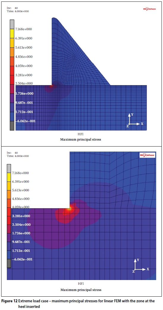
The maximum principal stress S1 for the linear case is 7.2 MPa. The normal stress Sy at the same position is 3.01 MPa. The yield stress for mass concrete is approximately between 2 and 3 MPa, which implies that material yielding will occur in the FEM at the heel of the wall.
Figure 13 presents the maximum principal stresses for the DP NL FEM analysis for the same load case as in Figure 12 (extreme load condition). The stress distributions for the linear and non-linear analyses can be compared. Note the lower principal tensile stress and the redistribution of the tensile stress at the heel of the wall.
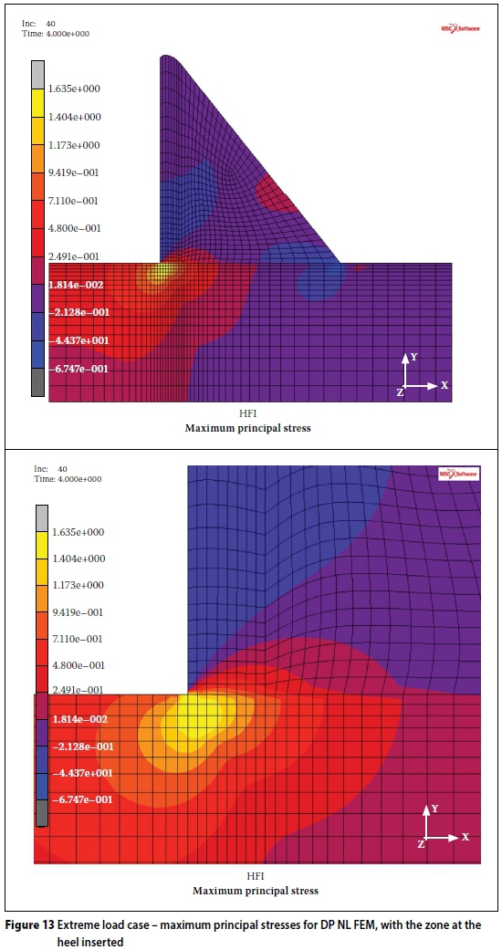
The maximum principal stress has now decreased from 7.2 MPa to 1.635 MPa. This indicates that some yielding has occurred at the heel of the wall.
To illustrate the yielding, a contour plot of the total EQPS for the extreme load case is presented in Figure 14. The region of non-zero EQPS can be interpreted as the region where the material changes from the linear to the non-linear state on the stress-strain curve.
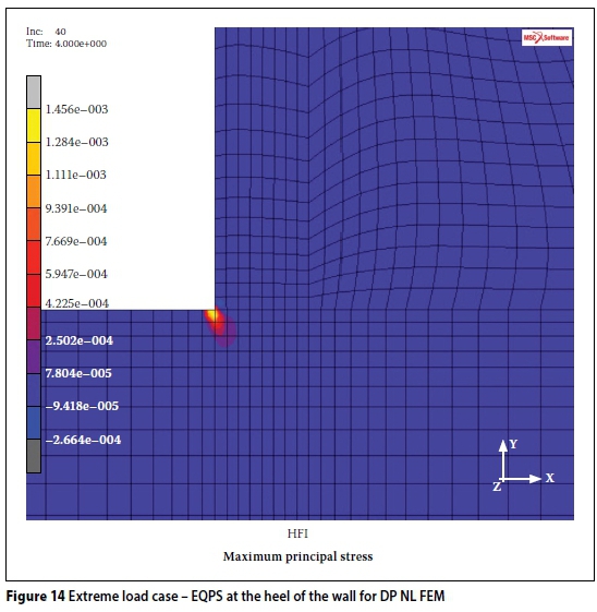
From Figure 14 it can be seen that the EQPS dips into the foundation at approximately 45° for a distance of approximately 3.5 m. This is a typical pattern where the material properties for the concrete wall and the rock foundation are of the same order. This failure pattern is also seen in fracture mechanics analyses of similar dams (Cai et al 2008).
The NL DP FE yield model can also be utilised in dam analysis where different material properties are used. For a worst-case scenario the same model was used, but with a weak or weathered residual layer of material between the concrete wall and the rock. Figure 15 illustrates the structural behaviour of this scenario. The tensile yield stress for the weak layer was assumed to be ft= 0.2 MPa. No contact elements were included and the FE mesh is thus homogeneous.
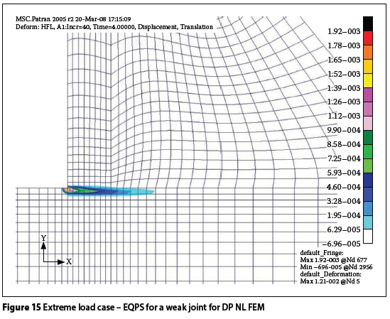
From Figure 15 it can be seen that the yield zone is along the weak layer and does not dip into the rock as in Figure 14. The EQPS contour plot shows that yielding could occur up to approximately 15.5 m (24%) of the base length for such an extreme load condition. This is useful to evaluate the condition of very old dams founded on weathered concrete or rock. Weak foundation layers or deep-seated sliding joints can be analysed in a similar manner.
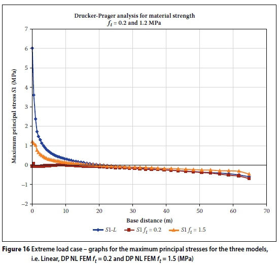
Figure 16 illustrates the maximum principal stress (S1) along the base of the wall for the extreme load case and for the following three analyses:
■ Linear analysis (indicated as S1-L)
■ NL DP FEM with equal concrete and rock material properties, ft= 1.5 MPa (indicated as S1 ft= 1.5)
■ NL DP FEM with weathered material along the base of the wall ft= 0.2 MPa and rockft = 1.5 MPa (indicated as S1 ft = 0.2).
From Figure 16 it can be seen that the stress graphs converge at approximately 15 metres from the heel of the wall. The weathered base layer produces very low stresses at the heel.
Factor of safety against sliding
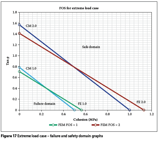
The critical factor of safety (FOS) of a gravity dam is typically the resistance against sliding. A "failure domain graph" (Oosthuizen 1985) is useful for determining the safety of a wall for given material properties, i.e. cohesion (c') and friction angle (φ), of the foundation at the contact surface. The values c' versus φ for the FOS against sliding equal to either 1.0 or 2.0 are determined.
The calculation for the FOS against sliding is performed in a similar manner as used for the CM:

where:
= sum of vertical loads, excluding uplift pressures
U = force due to uplift pressures
A = area of uncracked region along the base line
ΣH = sum of all horizontal loads, including tail-water pressures
c' = cohesion (apparent or real. For apparent cohesion a minimum value of compressive stress, σn, should be specified to determine the compressed area upon which cohesion could be mobilised)
φ = friction angle (peak value or residual value).
The failure domain is the area below the line for FOS = 1.0, and the safe domain the area above the line FOS = 2.0. Figure 17 illustrates the results of the analyses of these domains for the CM and the NL DP FEM (indicated as FEM) for the case study for the extreme load case and a concrete tensile yield of ft= 1.5 MPa. It is suggested that the NL DP FEM provides more reliable values for the required cohesion and internal friction angle.
PROPOSED METHODOLOGY FOR THE ANALYSIS OF A GRAVITY DAM
The following methodology for analysing gravity dams using the design criteria of the NL DP FEM is proposed:
■ Initially prepare the CM and the linear 2-D FEM analyses. For the FEM select a relatively coarse mesh (to minimise the stress peaks). From these analyses identify any problem areas. Aspects to consider are the topography, geology and material properties.
■ Perform an NL DP FEM and examine the area of non-zero EQPS to identify material yielding zones. Identify areas of extensive material failure. The safety of the structure is determined by standards laid down by the APP and the design engineer.
■ For existing dams the back-analysis should be compared with information from instrumentation and geodetic surveys.
■ As a first assumption, the material yielding regions, as detected from the EQPS plots, should preferably not exceed, say, 3% of the base width for a service load and 10% for an extreme load condition. These percentages are recommended by the authors and are based on past experience. The FOS against sliding is calculated from the summation of the computed normal stresses Sy, similar to the CM.
■ The 2-D FEM application illustrated here can be extended to 3-D analysis models. The Drucker-Prager yield model is compatible with a 3-D analysis. These models could include more aspects of the geometry and foundation details, such as geological joints and faults. 3-D analysis is important for dams where sliding along the flanks is of concern, i.e. where the wall is founded on steep flank formations (Lombardi 2007).
CONCLUDING REMARKS
The CM is still widely used to analyse gravity dams due to its straightforward approach. The CM has, however, limitations for back analysis on existing dams for dam safety evaluations, especially where weathered material is an important concern.
FEM analyses may use fine element meshes to incorporate more geometric detail. In the linear domain, the FEM is sensitive to mesh density and high stress peaks at singularity points. The non-linear FEM models analyse dams more accurately. For the use of contact elements the possible failure path should be postulated in advance. The NL fracture mechanics method (Cai et al 2008) is possibly a more accurate, but extremely complicated, method to employ in the design of gravity dams. This paper illustrates the possibilities of the non-linear Drucker-Prager yield model.
It has been illustrated that gravity dams can be analysed with the NL DP FEM with more certainty, and that the high stress peaks at the singularity points can be overcome. One advantage of the NL DP FEM is that the DP parameters can readily be obtained from standard material laboratory tests.
The NL DP FEM facilitates the design and optimisation of dams with more confidence. New design criteria related to construction materials and different cross-sections can be investigated, and safer margins of structural stability can be determined.
For the purpose of safety back analysis of existing dams, the NL DP FEM (the DP parameters based on the in-situ material properties) may be used as a precursor to, and as a check for, the more complex NL fracture mechanics method.
ACKNOWLEDGEMENTS
The authors wish to acknowledge and express their appreciation to the personnel of the Department of Water and Sanitation (DWS) Sub-directorate: Dam Safety and Surveillance, especially Prof C Oosthuizen for his valuable input. The DWS, who sponsored the research, is thanked for their permission to publish this paper. The opinions expressed in this paper are, however, those of the authors.
REFERENCES
Bhattacharjee, S S & Léger P 1994. Application of NLFM models to predict cracking in concrete gravity dams. Journal of Structural Engineering, 120(4): 1255-1271. [ Links ]
CADAM User's Manual 1.4.3 2001. Montreal, Canada: Department of Civil, Geological and Mining Engineering. [ Links ]
Cai, Q, Robberts, J M & Van Rensburg, B W J 2008. Finite element modelling of concrete gravity dams. Journal of the South African Institution of Civil Engineering, 50(1): 13-24. [ Links ]
Carpinteri, A, Valente, S V, Farrara, D & Imperato, L 1992. Experimental and numerical fracture modelling of a gravity dam. In: Bazant, Z P (Ed.), Fracture Mechanics of Concrete Structures, London: Elsevier Applied Science, pp 351-360. [ Links ]
Chen, W F 1982. Plasticity in Reinforced Concrete. New York: McGraw-Hill. [ Links ]
Durieux J H 2009. Development of a practical methodology for the analysis of gravity dams using the non-linear finite element method. MEng dissertation, University of Pretoria. [ Links ]
Professional Design Team 2005. De Hoop Dam: Design criteria memorandum for comparative dams. Internal report, DWAF, South Africa. [ Links ]
Professional Design Team 2007. De Hoop Dam: Material laboratory report on concrete materials and trial mixes. Internal report, Pretoria: Department of Water Affairs and Forestry. [ Links ]
Lombardi, G 2007. 3-D analysis of gravity dams. Hydropower and Dams, 1: 98-102. [ Links ]
MSC Marc User's Guide 2003. Munich, Germany: MSC Software GmbH. [ Links ]
Oosthuizen, C 1985. Methodology for the probabilistic evaluation of dams (part of a PhD thesis. San Rafael, CA, University of Columbia Pacific). Pretoria: Department of Water Affairs and Forestry. [ Links ]
Oosthuizen, C 2007. Personal communication related to the results of concrete material strength tested by the acoustic emission process for concrete loaded for long time periods. [ Links ]
USBR (United States Bureau of Reclamation) 1976. Design of gravity dams. Denver, CO: US Government Printing Office. [ Links ]
Zienkiewicz, O C 1977. Finite Element Method, 3rd ed. Maidenhead, UK: McGraw-Hill. [ Links ]
 Correspondence:
J H Durieux
PO Box 40050
Moreleta Park
Pretoria
0044
South Africa
T: +27 82 809 5302
E: durieuxh@gmail.com
B W J van Rensburg
Department of Civil Engineering
University of Pretoria
Pretoria
0002
South Africa
T: +27 12 420 2439
E: ben.vanrensburg@up.ac.za

HANS DURIEUX (Pr Eng) was enrolled for an MEng in Structural Engineering at the University of Pretoria when this paper was written. He retired at the end of August 2015, but is still active as a private consultant on a freelance basis. He previously worked in the Structural Division in the Directorate Asset Management at the Department of Water and Sanitation (DWS). He obtained his BSc Eng (Civil) at the University of Pretoria in 1972 and thereafter obtained a BSc Eng (Hons) in 1979 and MEng (Structural Engineering) in 2009. His work experience is in the field of planning and designing of water-related projects at the DWS. Over the last 24 years he has specialised in structural studies of dams, utilising the finite element method.

PROF BEN VAN RENSBURG (Pr Eng, FSAICE) is professor in the Department of Civil Engineering in the field of structural engineering. He started his career in consulting engineering and worked in a research organisation, subsequently joining the University of Pretoria. He obtained BSc and MSc degrees in Civil Engineering from the University of Pretoria, an MSc (Structural Engineering) from the University of Southampton and a PhD (Civil Engineering) from the University of Pretoria.


