


Services on Demand
Article
 English (pdf)
 Article in xml format
 Article references
Indicators

Related links
-
 Cited by Google
 -
 Similars in Google
Share

 Permalink
Journal of the South African Institution of Civil Engineering
On-line version ISSN 2309-8775
Print version ISSN 1021-2019
J. S. Afr. Inst. Civ. Eng. vol.57 n.4 Midrand Oct./Dec. 2015
http://dx.doi.org/10.17159/2309-8775/2015/v57n4a6
TECHNICAL PAPER
A study on the design and material costs of tall wind turbine towers in South Africa
A C Way; G P A G van Zijl
ABSTRACT
The aim of this project was to study the structural design and material costing of various designs of tall wind turbine towers and the associated foundations in a South African context. Design guidelines are proposed for the design of tubular steel, concrete and concrete-steel hybrid towers and foundations for hub heights of 80, 100 and 120 m. The results indicate that concrete and hybrid towers become viable alternatives to the conventional steel towers at hub heights equal to and above 100 m.
Three heights - 80 m, 100 m and 120 m - of each type of tower (steel, concrete and hybrid) and their foundations were designed according to the relevant design standards. The designs were verified using the Abaqus CAE finite element software (SIMULIA 2010). The material costs of the designs were calculated for a South African environment, according to the increases in material cost with increasing hub height.
In this paper, the required foundation sizes for the concrete and hybrid towers were found to be smaller than for the steel towers. The material costs of the concrete and hybrid towers were shown to be lower than for the steel towers, especially at hub heights above 100 m. An increase in hub height caused an increase in energy generation of 3.52% and 6.28% for 80 m to 100 m, and for 80 m to 120 m hub heights, respectively. It is postulated that the concrete and hybrid towers become viable alternatives to the conventional steel towers at hub heights above 100 m.
INTRODUCTION
Background and literature review
The introduction of the Renewable Energy Independent Power Producer Procurement Programme (REIPPPP) in August 2011 has led to a fast-growing renewable energy industry in South Africa, particularly in the wind power sector. In three years, South Africa has procured more investment in independent power generation than had been achieved across the African continent for the past 20 years (Eberhard et al 2014).
The REIPPPP saw fast-tracked competition develop in the South African wind power sector. This resulted in a reduction of the price of wind energy across the three bidding rounds, as can be seen in Figure 1 (Eberhard et al 2014). The rapid decrease in the price of wind energy is a sign of a fast-maturing industry, although many criticise the sudden drop in prices (due to over-competitiveness in the industry), arguing that this has negatively affected the potential for increased local content and sustainability. The lowered price for wind energy has nevertheless made it one of the main renewable energy sources in South Africa.

The current trend in the global wind industry is to use taller wind turbine towers to access the stronger and less turbulent wind resources that occur at greater heights (IRENA 2012). In 2012, approximately 90% of installed wind turbine towers were of the tubular steel type due to their cost-effectiveness and ease of construction (World Steel Association 2012). For hub heights of up to 80 m, tubular steel towers have proven themselves to be the most cost-effective solution. As the tower hub heights increase to 100 and 120 m, however, steel towers start to lose their appeal (Harte & van Zijl 2007).
One of the main reasons for the increasing hub height trend stems from the current situation of wind power in Europe. Many of the most favourable wind sites have already been exploited by currently operating wind farms, leaving only low to medium wind resource sites. In addition to this, recent advances in low to medium wind resource technology allow for the exploitation of sites that were previously considered to have unprofitable wind resources.
As the hub height increases, the towers need to be able to resist increased ultimate loads, bending moments and increased fatigue loads and moments. This is as a result of the greater wind loads acting on the tower, nacelle and blade assembly. Also to be taken into consideration is the stiffness requirement of the tower with regard to the interaction between the natural frequency of the tower and the rotational frequency of the turbine (Nicholson 2011). In order to satisfy these requirements, either the tower shell thickness needs to be increased, or the tower base diameter needs to be increased. The main problem with the steel tower occurs when tower base diameters are required to be larger than the allowable road transportation height limit of 4.5 m.
The development of turbines with nameplate capacity (i.e. maximum power generating capacity at optimal wind speed) in excess of 3 MW has also created the need for access to stronger wind resources. The added weight of these larger turbines and blades requires an increase in the structural strength of the towers. It is generally due to these reasons that different tower material and designs are currently being employed as an alternative to the conventional steel tower for taller hub heights.
Tower types
The three most common designs for tall wind turbine towers are:
■ the conventional tubular steel tower
■ the precast, post-tensioned, segmented concrete tower
■ the concrete-steel hybrid tower.
Tubular steel tower
The conventional steel tower is manufactured in 20-30 m sections that taper in diameter and shell thickness from top to bottom. This is the most common type of tower in the world, and as such there are established manufacturers around the world who have optimised the tower for hub heights of up to 80 m. This tower type has the advantage of rapid construction, as there are only three or four sections that need to be lifted into place. As previously mentioned, the base diameter is limited due to transport constraints, which causes a notable increase in tower shell thickness with increasing hub height (Cotrell et al 2014). There are currently no commercial scale steel towers that further split the sections into segments, due to the fatigue loads that would act on the connections between segments. In addition, even the smallest of manufacturing imperfections in connection components cause high stress concentrations that lead to fatigue failure.
Precast concrete tower
The precast concrete tower is generally manufactured off site in sections and further into segments, which alleviates the transportation problems associated with the large base-diameter sections prevalent in the taller steel towers. The segments are then transported to site where they are placed, grouted and post-tensioned. These towers have distinct advantages, other than the ease of transportation, in that the thicker concrete sections are stiffer than a typical steel tower section. This allows for reduced lateral deflections, longer fatigue life and higher tower natural frequencies. The disadvantages include the obvious lack of tensile strength of the concrete, creating the necessity for post-tensioning and the need for increased crane hire time.
Concrete-steel hybrid tower
The hybrid tower generally consists of a lower post-tensioned concrete section, ranging from 40-80 m, and an upper steel section (Nordex 2007). The lower sections can be cast in-situ, but are generally manufactured in segments like the precast concrete tower and transported to and assembled on site. This type of tower combines the benefits of both the steel and concrete towers, and only has the disadvantages of the concrete tower in the form of the post-tensioning requirement.
AIMS AND METHODOLOGY
This paper aims to:
a. Acquire and analyse South African wind data, ranging from 80-120 m above ground.
b. Study the design of wind turbine support structures and foundations for steel, post-tensioned concrete and concrete-steel hybrid type towers.
c. Determine whether an increase in tower height is viable for South Africa or not, by calculating the increase in the tower and foundation material costs as a function of tower height.
d. Develop guidelines for the South African wind industry with regard to the material costs and structural design of tall wind turbine towers.
Initially a literature study was conducted on the global and South African wind industries to gain a better understanding of the current status of, and trends in, the wind industry. An investigation into the wind resource and the available wind resource information in South Africa was performed to justify the use of taller wind turbine towers. A total of nine towers (concrete, steel and hybrid with heights of 80, 100 and 120 m) and their foundations were then designed according to the current international design methods.
The respective tower designs were then used to determine the material costs associated with increased hub height. Thereafter the increase in revenue generated as a result of increases in hub height was determined. The last two processes were carried out to develop an indication of whether increasing the hub height is a viable option in a South African context.
Note that the cost analysis in this paper is limited to the material cost. Clearly total cost should be considered when alternatives are compared for particular wind farms. For this emerging technology in the South African context it is left to the design team to consider particular scenarios of overall cost, including, amongst others, the construction method (for instance slip or climbing form-work versus hybrid construction requiring large crane-hoisting capacity); logistics of on-site precast versus precast in existing technology hubs where specialised labour and materials are available, and subsequent transportation to site; and the transportation of steel tower segments from producers in industrial zones (Coega in the Eastern Cape, and Atlantis in the Western Cape) to site, etc. Here light shed on possible disproportional raise in material cost with increase in tower height may be of significant value to designers, although it is acknowledged that such additional cost may be offset by savings in other cost items.
WIND RESOURCE ANALYSIS
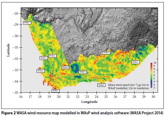
The wind resource analysis was based on data obtained from the Wind Atlas for South Africa (WASA 2014) project. This project aimed to set up a numerical wind atlas database for South Africa, a sample of which can be seen in Figure 2, which uses colour coding to differentiate between areas of high and low mean wind speeds.
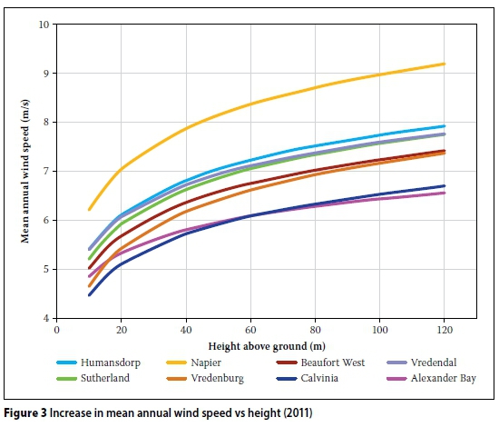
The project erected ten wind masts around South Africa (Western, Northern and Eastern Cape) in order to verify the database. This data was made freely available to the public and currently has three full years' worth of data (2011-2013). The masts have anemometers at altitudes of 10, 20, 40, 60 and 62 m in order to get an accurate representation of the wind profile at the given sites. The data was condensed and logarithmic extrapolation techniques were employed by the authors to extend the data to an altitude of 120 m. The data for eight of the ten masts (two contained large gaps in data) were used to calculate the increase in wind speed as a function of hub height, as can be seen in Figure 3. The average increases in mean wind speed values from 62 m hub height to 80, 100 and 120 m are 4.1%, 7.2% and 9.8% respectively.
DESIGN
The design philosophy of the International Electrotechnical Commission IEC 64001:2005 Wind turbines-part 1: Design requirements (IEC 2005) was followed. Each of the nine tower-and-foundation combinations was subjected to the Extreme Wind Speed Model (EWM), as set out in IEC 6400-1:2005.
Wind loads
In the EWM, the wind turbine is subjected to an extreme three-second wind gust (one-in-fifty year return period) of 52.5 m/s at hub height, as for IEC class IIIA. This value was compared to the equivalent in SANS 10160-3:2009 (SANS 2009) and was found to be more conservative than the wind speeds in the presence of even the worst terrain category (Category A). In this circumstance, the wind turbine is in a non-operational, parked state, with the blades feathered out of the wind, assuming a yaw-misalignment of 15 degrees. The design wind speed, Ve50(z), is distributed along the tower according to IEC 6400-1:2005, where Vref- is the ten-minute mean wind speed and z denotes height:
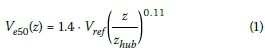
Note that in Equation 1 Vrefis the wind speed at the hub height zhub,. The EWM is a case of an ultimate limit state (ULS), and the design reflects this state. Load factors as prescribed in IEC 6400-1:2005 were used, in conjunction with factors from EN 19971:2004 (Eurocode 7) (EN 1997 2004) that are not contained in IEC 6400-1:2005. The pressure distribution around the circumference of the tower is done in accordance with section 8.10 in SANS 10160-3:2009, with particular use of Figure 29. In addition to the wind loading on the tower, there are also wind loads that act on the blades and nacelle. The loads are summarised in Figure 4.
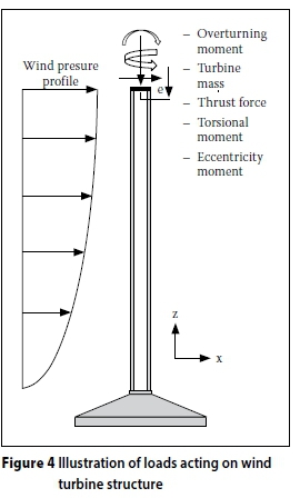
Loads on foundations
The loads from the tower transfer to the square foundation directly through an anchor cage. The loads that act on the foundation are thus the sum of the loads that act on the wind turbine. Two cases are assumed. The first is for the case of wind acting in the x-direction, as shown in Figure 4. The second case is for wind acting at 45 degrees to the x-direction, as seen in plan, which creates the necessity for the design of the foundations to consider these two different wind orientation cases.
Tower natural frequency
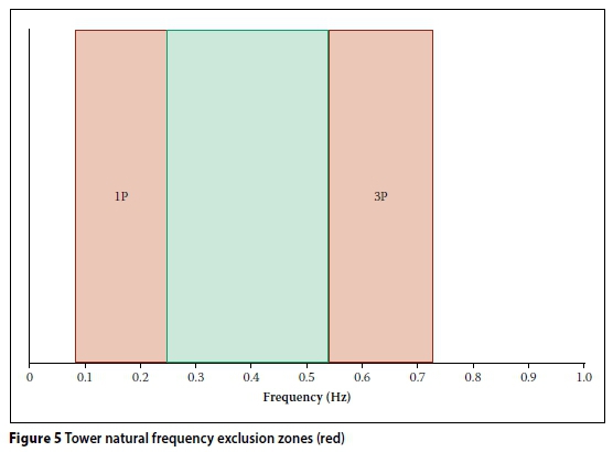
A crucial aspect of the design of any tower is the need to separate the natural frequency of the tower from the blade-passing frequency of the turbine. The natural frequency of the tower must be completely separated from the frequency range at which one blade passes the tower, across the operational frequency range of the turbine (denoted by 1P), plus 15% above and below. Similarly, the three blade passing frequency (3P) at rated power generation must be avoided by 15% on either side (ASCE/AWEA 2011). This is to ensure that there are no problems associated with resonance, due to the interaction between the turbine and the tower.
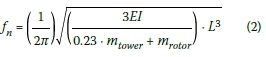
Resonance between the tower and the blade passing frequencies causes highly increased deflections of, and vibrations in, the tower. Resonant effects lead to increased and premature fatigue damage or, in the worst case, catastrophic failure of the tower. An approximate equation for the calculation of a tower's natural frequency,fn, is reproduced from Manwell et al (2010) in Equation 2, and is accurate to within 15%, but will be verified using the Abaqus FEM software. The natural frequency of the tower is affected by the tower material Young's Modulus, E, the second moment of inertia of the tower, I, the tower length, L, and the mass of the rotor and tower.
For the turbine used in this study, a Vestas V112 3MW, the feasible allowable tower natural frequency zone, is shown as being between 0.245 Hz and 0.544 Hz in Figure 5.
Foundation design
The foundations were all designed to be square shallow-gravity foundations. Water depths, varying from well below the foundation to ground level, were used in the design of the foundations. The soil conditions for this project were chosen to represent a typical wind turbine site along the coast of South Africa (c = 60 kN/m2, φ= 30°, defined below).
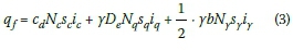
The foundations were designed with particular attention to the resistance against overturn, resistance against sliding of the base, soil and foundation stiffness, tensile reinforcing and resistance against punching shear. The calculation of the soil's bearing capacity, qfis carried out according to Craig (2004), where itrefers to inclination factors, Sirefers to foundation shape factors, Ni refers to bearing capacity factors and cd, γ, Deand b denote the soil cohesion intercept, the bulk density of the soil, the embedded depth of the foundation and the effective breadth of the foundation respectively:
The sliding resistance of the foundation is not usually a governing factor, but should be checked nevertheless, according to DNV/ Ris0 (2002), for drained and undrained soil conditions respectively, where φdenotes the design soil angle of shear resistance, Aejj denotes the effective area of the foundation, Vdis the vertical design load and Hdthe horizontal design sliding force.

One of the most important criteria of a foundation is to prevent overturn of the structure by an acceptable factor of safety. Put simply, the sum of the stabilising moments, Σ-ΜR, must outweigh the sum of the overturning moments,Σ-Μo by a factor, Fs:

The stiffness of the foundation is incorporated into the FEM model using linear springs, calculated according to the equations from section 8.4 of DNV/Ris0 (2002) for vertical, horizontal, rocking and torsional stiffness. The formulae are based on work done by Gazetas (1983) and Elsabee (1973).
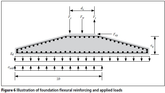
The flexural reinforcing in the foundation is present in both the top and bottom edges to resist the tensile stresses caused by the overturning moment from the wind loading, as shown in Figure 6. The design of the reinforced concrete foundation is performed according to EN 1992-1-1:2004 (EN 1992 2004).
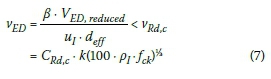
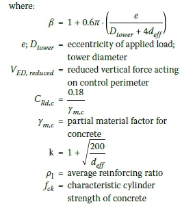
The foundations were designed to negate the need for punching shear reinforcing. The requirements were checked using section 6.4.3 of EN 1992-1-1:2004. The shear force, vED, at the first control perimeter, u1with an effective depth, def, must be less than the allowable shear stress for sections without shear reinforcing, vRdc:
Steel tower design
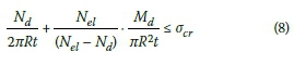
The design of the steel tower is generally governed by fatigue (not covered here), buckling resistance or stiffness requirements (either to limit deflections or to satisfy natural frequency requirements). The buckling requirements, as laid out in DNV/Ris0 (2002), are satisfied through the inequality as shown in Equation 8. The buckling requirements consider the axial force, Nd, bending moment, Md, tower shell thickness, t, tower radius, R, and the Euler elastic buckling load, Ne[. A combination of the applied axial force and bending moment must be less than the critical compressive stress, σcr:
The stiffness of the tower is acceptable when the natural frequency of the tower is within the acceptable limits, as shown in Figure 5. Wind turbine manufacturers sometimes limit the maximum lateral deflection of the tower, but such a limit is not included in this paper.
Concrete tower design
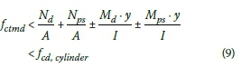
The design of the concrete tower is dominated by the tensile resistance (or the lack thereof) of the concrete. The tower therefore employs post-tensioning in order to limit the tensile stresses in the tower. The tower is designed so that the stresses that develop in the concrete sections are greater than the design mean tensile strength, fctmd, but lower than the design cylinder strength, fcicylinder, of the 50 MPa concrete (taking tension as negative and compression as positive) as shown in Equation 9. The symbols A, y, Npsand Mpsdenote the cross-sectional area, distance to the extreme fibre of section, axial force and moment caused by the post-tensioning, respectively.
The losses in pre-stressing force associated with post-tensioning (wobble friction, curvature friction, strand relaxation, elastic shortening, as well as anchoring) were considered using Equation 10, adapted from EN 1992-1-1:2004 in conjunction with the values shown in Table 1.
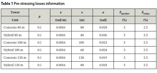
where:
δtotal= fraction of pre-stressing force lost to friction effects
μ= curvature friction coefficient
α= angle change along tendon length(rad)
κ= wobble friction coefficient (rad/m)
x = tendon length (m)
δanchor- = fraction of prestressing force lost due to anchorage
δre[ax= fraction of prestressing force lost to tendon relaxation effects
Concrete-steel hybrid tower design
As previously mentioned, the hybrid tower consists of a lower precast concrete section and a tubular steel tower upper section. The individual concrete and steel parts are designed with the same criteria as mentioned above for the steel and concrete sections respectively.
FEM ANALYSES
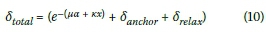
All nine of the designs were modelled using the Abaqus CAE FEM software. The tower and foundation combinations were modelled using 3D solid elements. Initially there was concern as to whether the 3D elements would result in sufficient accuracy, due to the small number of elements required across the thickness of the tower shell. Four elements over the tower shell thickness resulted in the number of elements in the model reaching into the millions. The mesh size was thus varied from four elements to one element over the shell thickness and the accuracy was compared for a natural frequency analysis. The results are shown in Table 2. Note that a simplification is possible by using shell elements. In an accompanying paper (Van Zyl & van Zijl 2015) (see pages 38-44 of this edition), where physical inelasticity in the form of cracking was incorporated, this was in fact done for feasibility.
It was concluded that mesh sizes up to three times the tower shell thickness yield results with errors of less than 1.5%, but only when the stresses and strains across the shell thickness are not of importance.
The models consisted of 8-node linear hexagonal "brick" elements for the tower and non-inclined portions of the foundations, with 4-node linear tetrahedral elements being used for the inclined portion of the foundations.
Analyses performed
Each of the nine tower and foundation combinations was subjected to three analyses. First, a modal frequency analysis was performed to accurately determine the natural frequency of the model and determine if it satisfied the natural frequency range requirements.
The second analysis involved the calculation of the buckling stress of each tower. In this analysis, the ultimate loads are applied to the structure and the analysis determines a factor relative to the buckling load to describe how safe or under-designed the model is. A factor of 1 indicates that the model is exactly on the brink of failure due to buckling. Values less than 1 indicate failure, and values over 1 indicate safety against buckling failure.
The final analysis was a two-step static load analysis with the ultimate limit state loads applied to the wind turbine structure. This was carried out with the intent of verifying the hand-calculated stresses and to check tower-top deflections. The second part of the analysis then used the deflections of the towers to determine the additional moments exerted on the tower due to the permanent loads acting at an eccentricity from the static centre of gravity (known as the P - Δ effect).
Loads
The loads for the static and buckling analyses included, as illustrated by Figure 7, are:

■ Wind loads acting directly on the tower
■ Wind loads acting on the nacelle, blades and nose-cone
■ Own weight of tower and turbine
■ Torsional moment on the tower
■ Tower top weight eccentricity
■ Vertical post-tensioning loads on the tower, where applicable.
Effect of underlying soil
The effect of the underlying soil is taken into account through the use of linear springs. The spring values are based on the previously-mentioned work by Gazetas (1983) and Elsabee (1973) found in DNV/Ris0 (2002). The springs were distributed around the underside of the foundation in the Abaqus model, simulating the vertical, horziontal, rocking and torsional stiffness of the underlying soil.
RESULTS
Tower and foundation dimensions
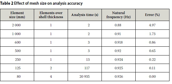
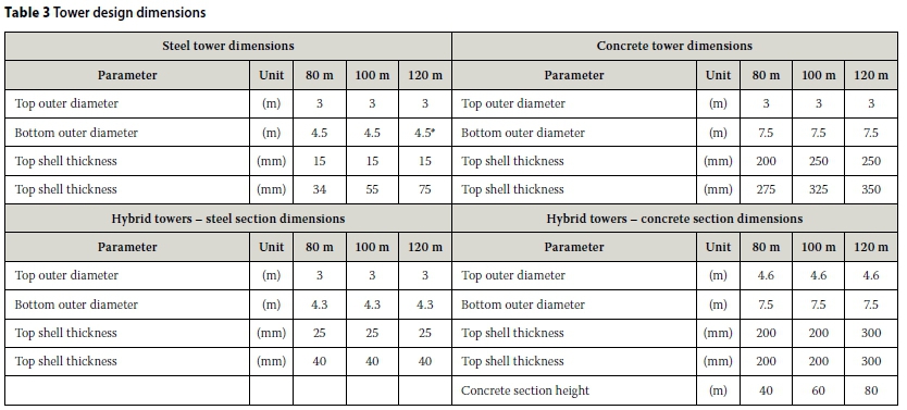
The final tower and foundation dimensions that satisfy the requirements as described above are shown in Tables 3 and 4.
The asterisk in Table 3, under the 120 m steel tower, indicates that this tower does not satisfy the natural frequency stiffness requirements. A frequency separation of only 12% could be achieved between the 1P and tower natural frequency, despite keeping the tower diameter at 4.5 for the first 45 metres of the tower. As can be seen, the concrete sections are notably thicker than their steel counterparts. This is due to concrete's relatively limited capacity for tension and compression strength, as well as a lower material stiffness in comparison to steel.
As can be seen in Table 4, the foundation volume is proportional to the tower height. An increase in tower height requires an increase in foundation concrete volume for one of the following reasons: to provide weight to counter the tower overturning moment, to provide extra foundation height negating the need for punching shear reinforcing, to increase the spread area of the foundation to prevent bearing capacity failure, or to provide more weight at the base in order to raise the natural frequency of the system.
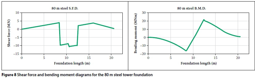
An example of the shear force and bending moment diagram for the 80 m steel tower foundation is shown in Figure 8. The maxima and minima from the graphs will be even greater for IEC wind classes II and I.
The foundation designs were all governed by the case where the water table is at ground level, as a considerable buoyancy force acts upwards on the foundation. The steel and hybrid tower foundations were all governed by the need for foundation weight to counter the overturning moment from the wind loading. The 80 m concrete tower was governed by the same case, but as the weight increased, the 100 m tower foundation was governed by simultaneous overturn and bearing capacity failure.
As the weight increased even more, the 120 m concrete tower foundation design was governed by the bearing capacity of the soil. The fictional site had quite favourable soil conditions, and so the bearing capacity was not prevalent. In weaker soils (lower and φvalues), bearing capacity is likely to be more prevalent as the governing foundation design parameter. Thus in the presence of weak soils, the steel and hybrid towers will be more appropriate, as they are lighter than the concrete towers.
FEM Results
Natural frequency analyses
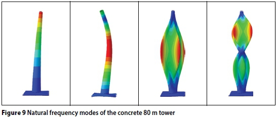
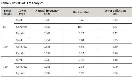
A natural frequency analysis was carried out on all nine of the models, all of which, except the 120 m steel tower, satisfied the natural frequency requirements (0.245 Hz < fn< 0.544 Hz). The hand calculations compared well with the FEM results, the greatest error in natural frequency hand calculation being 12.6%. The first four natural frequency modes of the 80 m concrete tower are shown in Figure 9. The first (lowest) natural frequency of each tower can be seen in Table 5. As can be seen in Table 5, the concrete and hybrid towers do not have problems associated with low natural frequencies (lack of tower stiffness). Conversely though, they can sometimes have natural frequencies that are too high (overly stiff tower), depending on the choice of turbine.
Buckling analyses
Similarly, a buckling analysis was carried out on all nine models, the results of which compare well with the buckling stress hand calculations and confirm that the buckling capacity is not a governing factor in the design of the towers studied in this project. The results of the buckling analyses can be seen in Table 5. It should be noted that the hand calculations were acceptably conservative for all nine designs.
Tower deflection
The deflection of the towers at the ULS is also shown in Table 5. Deflections are not calculated at SLS, as wind speeds at SLS only reach 25 m/s before the turbine automatically shuts down and its blades are feathered out of the wind to reduce excess drag at higher ULS wind speeds (52.5 m/s). Furthermore, due to the nature of the structure, SLS deflections do not hinder the functionality of the turbine and are thus of little concern, whereas excessive ULS deflections are more likely to damage the turbine.
Similar studies prescribe a rule-of-thumb maximum tower top deflection of 1.25% of the tower height in order to protect the turbine against deflection-induced damage (Nicholson 2011). One can see that the deflections of the steel towers are considerably higher than that of the stiffer concrete and hybrid towers. Tower top deflections are sometimes limited by turbine suppliers and it is thus a possibility that the steel towers may have to be further stiffened in order to comply with this requirement, although all of them are lower than 1.25% of the tower heights.
Tower stresses
The tower stresses were obtained from the static analysis carried out on all the designs. As predicted, the hand calculations are conservative in comparison to the FEM results, as illustrated in the graphs in Figure 10. This figure illustrates the tension and compression side (windward and leeward side) of the 80 m concrete tower. Tensile stresses are shown as negative, and compression as positive values.
One can see that the hand-calculated tension stresses vary from the FEM values. This is likely due to the fact that the hand calculations assume that the tower is completely fixed at the base, whereas the FEM model considers the non-fixity of the base (in the form of the springs on the underside of the foundation, allowing small deflections due to the elasticity of the soil).
Most importantly, the extreme values (tension in concrete and compression in steel) in the FEM outputs are less critical than the hand calculation, which indicates safe design.
Pre-stressing
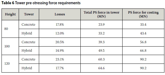
The loss in pre-stressing force for the concrete towers is considerably higher than that of the hybrid towers. This is due to the extra length of pre-stressing required in the concrete towers. Even though the concrete portion of the hybrid tower is shorter than the concrete tower, the hybrid tower requires more overall pre-stressing force than the concrete towers, as can be seen in Table 6. This is mainly due to the concrete sections in the hybrid towers being thinner than the concrete towers.
Material cost comparison
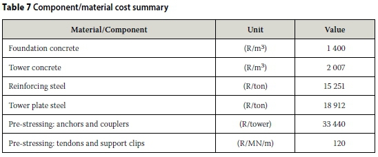
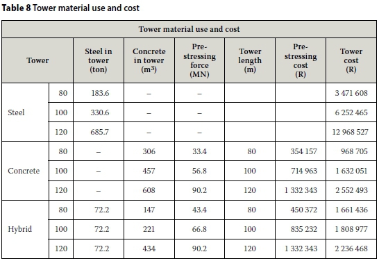
The costs used in the material cost comparison were obtained from South African manufacturers and suppliers, and are exclusive of labour, due to the material cost comparison nature of this project. The costs used are an average of the 2014 prices obtained from various suppliers/manufacturers in South Africa and can be seen in Table 7. The material cost of the tower and foundations are shown in Figure 11 and Table 8 and include the tower material used, the foundation concrete and reinforcing and the pre-stressing material costs.
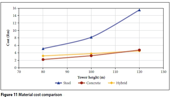
Material costs are not the only costs associated with the production and erection of the tower and foundation. Other costs associated with transport, and labour and lifting costs, amongst others, also play a role in determining the cost of a finished product. As can be seen from Figure 11, the concrete and hybrid towers are less material-cost-intensive than the steel towers, particularly for the 100 and 120 m towers. The trend seems to show that the hybrid towers will become more cost effective than the concrete towers at hub heights greater than 110-115 m. The steel towers are shown to be disproportionately material-cost-intensive at hub heights greater than 100 m.
Increase in revenue generation
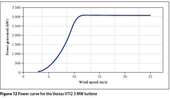
The data obtained from the WASA project for the Napier mast was used to calculate the increase in revenue generated as a function of increases in hub height. This specific site has a middle-of-the-range increase in wind speed as function of hub height, and serves as a good example of how increasing the hub height can be beneficial to both investor and power utility. In Table 9 the annual average wind speed for the three years of data (2011 to 2013) are given for the 80 m hub height, as well as the logarithmically extrapolated values for the 100 m and 120 m hub heights. A single Vestas V112 3MW turbine was used in the calculation of the increase in energy generated, with the 80 m hub height as reference. For the total annual energy generated, the following expression is used:
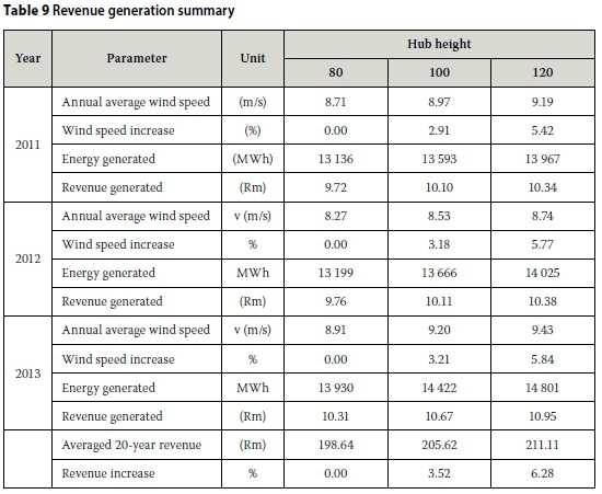
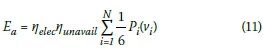
where vtis the wind velocity for the particular site obtained from WASA and extrapolated to the relevant hub height, Pi(vi) is the power generated by the particular turbine at the particular velocity yelecis a coefficient correcting for losses in generation and feeding into the grid, and nunavailis a coefficient for losses due to unavailability of the turbine. See Figure 12 for the particular power curve used in this paper. Note further that N is the total number of wind readings per year, i.e. six per hour for 24 hours and 365 days per year, and typical values of nelec= 0.97 and nunavail= 0.95 have been used here (Feng & Tavner 2010). Subsequently the yearly revenue is calculated by multiplying the annual energy Eawith the unit price R0.74/kWh (see Figure 1) of REIPPP Round 3. For an increase in hub height from 80 to 100 m and from 80 to 120 m, an increase in revenue of 3.52% and 6.28% was found. The results can be seen in Table 9. It should be noted that the 20 year average shown in Table 9 is an extrapolation of the three years of data that was analysed.
CONCLUSIONS
The designs of the wind turbine foundations were highly dependent on the choice of underlying soil parameters. Given the favourable soil conditions used in this project, the design of the foundation for the steel and hybrid towers was governed by the weight of the foundation needed to stabilise the structure against overturning. This was for the case of the water table being at ground level. The foundation design of the concrete towers was governed by a combination of bearing capacity and foundation weight required to stabilise against overturning, also for the case of water table at ground-surface level.
The amount of reinforcing steel in the foundation was governed by the minimum reinforcing requirement in EN 1992-1-1, although this may not be the case when designing for IEC wind classes II or I. None of the foundations are subject to punching shear failure, even without punching shear reinforcement, although the concrete towers were just under the limit for requiring punching shear reinforcement. Foundations for concrete towers taller than 120 m will not be able to provide sufficient shear resistance without shear reinforcing, while the steel and hybrid tower foundations may still have adequate shear resistance.
The steel tower design was governed by the natural frequency stiffness requirements of the tower, primarily, to ensure that the natural frequency lies within the acceptable limits as determined by the choice of turbine, but also to limit deflections. The design of both the concrete and hybrid towers was dictated by the lack of tensile resistance of the concrete.
The tensile stresses in the sections (reduced by post-tensioning) thus governed the design of the concrete sections, although buckling may become an important design factor when designing towers taller than 120 m.
According to the results from this project, it can be seen that the material requirements associated with the foundation of concrete and hybrid wind turbine towers are lower than those of the steel towers for the given design assumptions. Consequently, and additionally, the material cost of the studied steel towers and foundations in a South African context are higher than their concrete and hybrid counterparts, particularly for hub heights in excess of 100 m.
The increased revenue, due to increases in hub height from 80 m to 100 m and 120 m for a Vestas V112-3MW turbine, was shown to be in the vicinity of 3.52% and 6.28% respectively, with average capacity factor increases of the same magnitudes. It remains to be verified whether these additional revenues exceed the added total costs to realise the higher towers.
REFERENCES
ASCE/AWEA 2011. Recommended practice for compliance of large land-based wind turbine support structures. Washington DC: American Society of Civil Engineers and the American Wind Energy Association. [ Links ]
Cotrell, J, Stehly, T, Johnson, J, Roberts, J O, Parker, Z, Scott, G & Heimiller, D 2014. Analysis of transportation and logistics challeges affecting the deployment of larger wind turbine towers: Summary results. Denver, CO, US: National Renewable Energy Laboratory. [ Links ]
Craig, R F 2004. Craig's Soil Mechanics, 7th ed. New York: Spon Press. [ Links ]
DNV/Risø 2002. Guidelines for Design of Wind Turbines. 2nd ed. Copenhagen, Denmark: Det Norske Veritas (DNV) and Risø National Laboratory. [ Links ]
Eberhard, A, Kolker, J & Leigland, J 2014. South Africa's Renewable Energy IPP Procurement Program: Success factors and lessons. Washington DC: Public-Private Infrastructure Advisory Facility (PPIAF). [ Links ]
Elsabee, F 1973. Static stiffness coefficients for circular foundations embedded in an elastic medium. MSc in Civil Engineering, Boston, MA, US: Massachusetts Institute of Technology. [ Links ]
EN (European Standard) 1992 (2004). EN 1992-1-1: Eurocode 2: Design of Concrete Structures. Part 1-1: General Rules and Rules for Buildings. Brussels, Belgium: European Committee for Standardization (CEN). [ Links ]
EN (European Standard) 1997 (2004). EN 1997-1: Eurocode 7: Geotechnical Design. Part 1: General Rules. Brussels, Belgium: European Committee for Standardisation (CEN). [ Links ]
Feng, Y & Tavner, P 2010. Introduction to wind turbines: Reliability and availability. Durham, UK: Durham University. [ Links ]
Harte, R & Van Zijl, G P A G 2007. Structural stability of concrete wind turbines and solar chimney towers exposed to dynamic wind action. Journal of Wind Engineering and Industrial Aerodynamics (JWEIA), 95 (9-11): 1079-1096. [ Links ]
Gazetas, G 1983. Analysis of machine foundation vibrations: State of the art. Soil Dynamics and Earthquake Engineering, 2(1): 32 [ Links ]
. IEC (International Electrotechnical Commission) 2005. IEC 6400-1:2005. Wind turbines. Part 1: Design requirements. Geneva: IEC. [ Links ]
IRENA (International Renewable Energy Agency) 2012. Renewable energy technologies. Cost analysis series - Wind power. Abu Dhabi, United Arab Emirates: IRENA. [ Links ]
Manwell, J, McGowan, J & Rogers, A 2010. Wind Energy Explained: Theory, Design and Application. Chichester, UK: Wiley. [ Links ]
Nicholson, J C 2011. Design of wind turbine tower and foundation systems: Optimization approach. MSc thesis, Iowa, IA, UK: University of Iowa. [ Links ]
Nordex 2007. Added yields in non-coastal regions. Hamburg: Nordex Wind Power SE. Available at: http://www.nordex-online.com/en/products-services/hybrid-towers.html [accessed on 18 September 2014]. [ Links ]
SANS (South African National Standard) 2009. SANS 10160-3:2009. Basis of Structural Design and Actions for Buildings and Industrial Structures. Part 3: Wind Actions. Pretoria: SABS Standards Division. [ Links ]
SIMULIA 2010. Abaqus CAE Finite element analysis software. Version 6.10-2. Vélizy-Villacoublay, France: Dassault Systems. [ Links ]
Van Zyl, W S & Van Zijl, G P A G 2015. Dynamic behaviour of normally reinforced concrete wind turbine support structures. Journal of the South African Institution of Civil Engineering, 57(4): 38-44. [ Links ]
WASA (Wind Atlas for South Africa) 2014. Mean wind speed atlas for parts of South Africa, Digital image. Pretoria: SA Department of Energy (DoE) [accessed 22 September 2014]. [ Links ]
World Steel Association 2012. Steel solutions in the green economy: Wind turbines, Brussels, Belgium: World Steel Association. [ Links ]
 Correspondence:
ANDREW WAY
Institute of Structural Engineering
Stellenbosch University
Private Bag X1
Matieland 7602
South Africa
T: +27 (0)72 679 0586
E: away@eceng.co.za
GIDEON VAN ZIJL
Department of Civil Engineering
Stellenbosch University
Private Bag X1
Matieland 7602
South Africa
T: +27 (0)21 808 4436
E: gvanzijl@sun.ac.za

ANDREW WAY, who is a student member of SAICE, obtained his Bachelor's (2012) degree and his Master's (2014) in Civil Engineering from Stellenbosch University. This paper is a condensed version of his Master's thesis, which focuses on wind power in South Africa and the structural design of wind turbine support structures.

PROF GIDEON VAN ZIJL (Pr Eng MSAICE) is professor in structural engineering at Stellenbosch University. He obtained his Bachelor's (1986) and Master's (1990) degrees in Civil Engineering from Stellenbosch University, and his PhD (2000) from Delft University in the Netherlands. As Director of the Centre for Development of Sustainable Infrastructure, his research interests are structural and computational mechanics, including the development, characterisation, and constitutive and durability modelling of advanced construction materials.

