


Servicios Personalizados
Articulo
 Inglés (pdf)
 Articulo en XML
 Referencias del artículo
Indicadores

Links relacionados
-
 Citado por Google
 -
 Similares en Google
Compartir

 Permalink
Journal of the South African Institution of Civil Engineering
versión On-line ISSN 2309-8775
versión impresa ISSN 1021-2019
J. S. Afr. Inst. Civ. Eng. vol.57 no.4 Midrand oct./dic. 2015
http://dx.doi.org/10.17159/2309-8775/2015/v57n4a5
TECHNICAL PAPER
Dynamic behaviour of normally reinforced concrete wind turbine support structures
W S van Zyl; G P A G van Zijl
ABSTRACT
Transportation logistics of large steel towers have led to concrete towers becoming a viable option. There are currently no design codes dealing exclusively with the design of concrete wind turbine towers. Wind turbine towers have strict constraints on the fundamental frequency of the tower to avoid resonance. This paper investigates the dynamic behaviour of wind turbine towers using nonlinear finite element modelling. Focus is placed on the effect of crack formation and soil stiffness on the fundamental frequency of the tower. An analytical model is then proposed that can be used in the primary design stage to determine the geometry of the tower that satisfies the fundamental frequency requirements.
INTRODUCTION
Modern civilisation is dependent on energy. The global energy demand is steadily rising each year and is accompanied by rising greenhouse gas emissions. Global warming is a real danger, and governments worldwide are implementing goals to generate large percentages of their countries' energy needs with renewable energy. The Global Wind Energy Council (GWEC) predicts that by 2035 renewable energy will be generating more than 25% of the world's electricity needs, with a quarter of this coming from wind energy (GWEC 2013). Wind energy is currently the second largest renewable energy source, after hydro power, and it has been growing exponentially over the last decade.
South Africa (SA) has the seventh largest coal reserve in the world. In 2012, 72% of the country's electricity was being produced by coal, 24% by oil and natural gas, 3% by nuclear, and less than 1% by renewable energy. This dependence on hydrocarbons, particularly coal, has made SA the twelfth largest CO2 emitter in the world (GWEC 2013).
The Renewable Energy Independent Power Producer Procurement Programme (REIPPPP) was created to encourage the exploitation of SA's vast renewable energy reserves. SA's long-term energy blueprint, the Integrated Resource Plan (IRP), specifies that about 9 000 MW of electricity must be produced by wind energy by 2030. The first phase of 634 MW of wind energy is currently in operation and is connected to the national electricity grid. The second phase of 562 MW is currently under construction, and the third and fourth phases are still in the bidding phase and will have a generating capacity of 787 MW and 590 MW respectively.
Concrete support structures
The worldwide movement to generate large amounts of electricity with wind turbines has led to a significant increase in the generating capacity of wind turbines. The capacity of turbines has increased from a couple of kilowatts in the 1970s to anything between 2 000 and 7 500 kilowatt today.
Modern turbines require higher support structures, as higher wind speeds, combined with longer blades, are necessary to increase their generating capacity. The standard 80-90 m tower is thus not economically viable anymore. The base diameter of a steel tower is limited to approximately 4.2 m due to transportation logistics. The diameter limitations make steel towers uneconomical at hub heights greater than approximately 80-90 m. One solution to the height limitation is to use concrete towers. Concrete wind turbine towers can either be precast and assembled on site, or slip-formed. This has the advantage that the tower segments can either be made small enough to be transported by normal truck or the tower can be produced on site. This overcomes the limitation on the diameter of the tower, and therefore there is no limitation on the height that is achievable.
There are currently no structural design codes that specifically give design guidelines for the design of concrete wind turbine towers. This has resulted in a handful of companies worldwide, with the knowledge to design these towers, having a monopoly in the industry.
The overall objective of this paper is to propose a design procedure for a concrete wind turbine tower. A nonlinear finite element model (FEM) is used as a design tool to evaluate the tower. Focus is placed on determining the appropriate wind models and wind loads to accurately model the tower. The FEM is then used to study the behaviour of the tower under different loading conditions to determine the critical design load case. The effect that crack formation has on the stiffness and dynamic behaviour of the tower is studied, and a sensitivity analysis is done to determine the effect of soil stiffness on the fundamental frequency of the tower. Different structural design codes are then used to create an analytical design method that can be used in the preliminary design stage, and that in certain cases may even be appropriate to use in the final design stage. The analytical design method is compared to the FEM to determine its accuracy.
This paper only focuses on the dynamic behaviour of the structure and investigates the effect of crack formation and soil stiffness on the fundamental frequency of the tower.
Dynamic behaviour of wind turbine towers
The fundamental frequency of structures exposed to dynamic loading is of vital importance to avoid resonance. Resonance occurs when an external dynamic force is applied to a structure at the same frequency as the structure's natural frequency. This causes the structure to undergo large displacements and can cause immediate failure or fatigue failure over time. There are mainly two methods to ensure that a structure is dynamically safe. The first is to ensure that the fundamental frequency of the structure does not coincide with any external vibration frequency that the structure may experience in its life. The second method uses damping to decrease the dynamic amplification of an external vibration force.
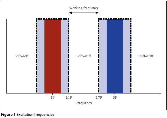
In the wind turbine tower industry, method one is preferred. Wind turbine structures are exposed to multiple excitation frequencies that can cause the structure to vibrate. The most important of these excitation frequencies is the blade rotational frequency, known as the 1P frequency, and the blade passing frequency, known as the 3P frequency. The 1P, or rotor revolution frequency, is caused by the unbalanced weight of the rotor, wind shear and tower shadow (DNV & Riso 2002). Modern wind turbines are variable speed turbines, thus the 1P and 3P frequencies are not single frequencies but a frequency interval. There are three different design options. The first is to design a structure with a fundamental frequency higher than the 3P frequency interval, called a stiff-stiff structure. The second option is to design a structure with fundamental frequency between the 1P and 3P frequency intervals, called a soft-stiff structure. The third option is to design a structure with fundamental frequency below the 1P frequency known as a soft-soft structure. This concept is illustrated in Figure 1. It has been shown that a soft-stiff structure is the most economical for wind turbine towers (Harte & Van Zijl 2007). It is difficult to calculate the exact fundamental frequency of a structure at the design stage, as there are various factors that may influence the frequency. Due to this uncertainty, the frequency of the tower is kept out of ±10% of the 1P and 3P frequency intervals (DNV & Riso 2002). The frequency between the 1.1P and 2.7P frequencies, is defined as the working frequency.
It is estimated that, by assuming the foundation to be fully fixed, the error in the fundamental frequency of the tower can be up to 20% (DNV & Riso 2002). Wind turbine guidelines generally propose that elastic springs be used to simulate the soil stiffness.
FINITE ELEMENT MODEL (FEM)
In this paper, a concrete wind turbine tower is modelled in the finite element package Diana (2012).
Geometry
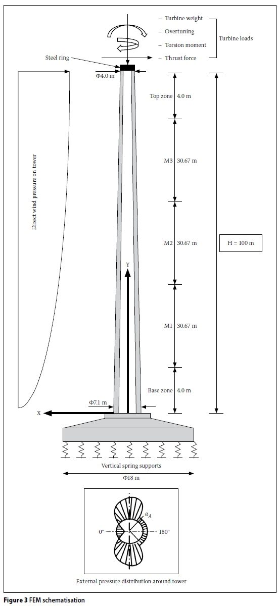
A typical wind turbine is illustrated in Figure 2. The tower has a conical profile, with the diameter and wall thickness reducing with height. This is due to the fact that the bending moment and shear force are at a maximum at foundation level and then reduce to the top. Reducing the diameter and wall thickness saves unnecessary weight and costs.

Material
Internationally high-strength concrete (HSC) is commonly used in high-rise buildings because of its ability to reduce the size and weight of structural elements. In recent years, HSC has also been used in some buildings in SA. The high compression strength and high stiffness of HSC make it ideal for concrete wind turbine towers.
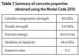
The physical properties of the concrete are calculated using the Model Code (FIB 2010). The Model Code forms the basis of many of today's concrete design codes, including the Eurocode. The 2010 edition of the Model Code includes material properties for HSC. The properties from the code for a class C80/95 concrete used here, are given in Table 1.
Diana offers various predefined finite element material models that describe the material behaviour under specific loading conditions. The material behaviour of the concrete is divided into concrete failing in compression (crushing) and concrete failing in tension (cracking).
A plasticity model is used to describe the concrete's behaviour in compression. When comparing elastic and plastic material behaviour, the main difference is that an elastic material will undergo no permanent deformation and a plastic material will undergo permanent or irreversible deformations.
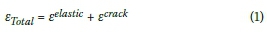
A total strain-based smeared cracking model is used to model the crack behaviour of concrete in Diana (Feenstra et al 1991). Whilst alternative models in continuum plasticity or damage could be used, this model has been shown to be robust and reasonably accurate, and allows nonlinear com-pressive and tensile behaviour of concrete to be described separately from typical concrete characterisation test data. As the name suggests, the crack width is smeared out or averaged over an element. This is different to a discrete cracking model where two or more elements lose contact with each other and a physical gap occurs. The total strain of the smeared cracking model is decomposed into an elastic strain component and a crack strain component:
A crack is formed when the principal tensile stress violates the maximum tensile strength condition. The tensile strength of the material can then either be reduced to zero immediately, or it can gradually decrease to zero - the latter is known as tension softening and is governed by fracture energy. A rotating crack model that reorients the crack direction, so that it will always coincide with the principal stress direction, is used. If the stress in a crack is reversed, the crack will close and the material retains its full compressive strength. The tensile strength, however, is lost and the crack will reopen once tensile strains reoccur.
Mesh and element type
Eight node curved shell elements are used to model the tower structure. A normal curved shell element has five degrees of freedom in every element node, three translations and two rotations. Thus, the basic variables of the curved shell elements are the translations ux, Uyand uzin the global XYZ directions, and the rotations φχand φyrespectively around the local x and y axes in the tangent plane.
Reinforcing bar elements are used to model the reinforcing steel in the concrete. Reinforcing elements do not have their own degrees of freedom. When embedded, the displacements and strains of the reinforcing element are fully coupled to that of the element in which it is embedded. The reinforcing element adds stiffness to the elements in which it is embedded. A bar element only adds stiffness in the axial direction of the bar.
Loads
The loading on wind turbine structures is unique when compared to normal concrete structures. Structural engineers are used to working with building structures of which the loading is dominated by the structure's own weight and live loads, such as people and moveable loads in the building. Provision for wind loads is usually made by incorporating shear walls into the building frame. What makes wind turbine towers unique, is that the live loads on these types of structures are negligibly small. Instead, the tower's loading is dominated by wind loading and the own weight of the structure is actually beneficial for resisting the wind loads. The wind loads acting on the tower are translated into direct wind pressure on the tower and turbine loads.
The direct wind pressure acting on the tower causes a positive pressure on the windward side and a negative pressure on the sides and back of the tower. This is illustrated in Figure 3. Wind pressure on the blades, hub and nacelle (generator housing) is transferred to the top of the tower. These forces are known as turbine loads and are the largest loads imposed on the tower.
Foundation stiffness effect
The foundation is a vital part of a wind turbine tower design. The foundation cannot be assumed to be fixed when the fundamental frequency of the tower is computed. Studies have shown that the effect of stiffness of the foundation itself on the fundamental frequency of the tower is small when compared to the effect of the soil stiffness (DNV & Riso 2002).
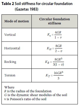
The soil stiffness and soil-foundation interaction can be modelled in detail through the use of soil elements and interface elements respectively, but this is a time-consuming and computationally expensive procedure. Another method that is commonly used involves the use of linear springs to represent the soil stiffness. This is a simple and cost-effective method to simulate the effect of the soil stiffness on the dynamic behaviour of the tower. The soil stiffness is uncoupled into a vertical, horizontal, rotational and torsional stiffness component. The foundation itself is then assumed to be rigid and supported on the appropriate springs. One of the most commonly used models for representing the stiffness of the soil through linear springs, is the method described by George Gazetas in his paper on machine foundation vibrations in 1983 (Gazetas 1983). The equations for calculating the soil stiffness of a foundation on a homogeneous half space is given in Table 2.
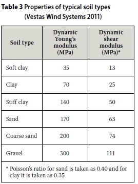
The rocking motion is the dominant mode for the tower. The foundation is thus supported on vertical springs that give the same rocking stiffness as the stiffness calculated by Gazetas's method. A sensitivity analysis is done to determine the effect of soil stiffness on the fundamental frequency of the tower. Typical soil types and their properties are given in Table 3. These generic soil types are used for the sensitivity analysis.
FEM analysis
The FEM is analysed for structural strength using a static non-linear analysis. The analysis is non-linear in terms of geometry and material properties, i.e. geometrical and physical nonlinearity is considered.
The natural frequency of the tower is computed using an Eigen value analysis. The Eigen value analysis is first computed using the uncracked tower. This step may not be required by all FE software. In Diana this initiates matrices for subsequent calculation of frequencies in the cracked state. It is also interesting to have knowledge of these frequencies in the uncracked state. A static non-linear analysis is then used to determine the tangent stiffness of the cracked tower, and finally the tangent stiffness of the tower is used to compute the natural frequency of the tower in the cracked state. The FEM model used, is schematised in Figure 3.
ANALYTICAL DESIGN METHODS
The finite element method is an excellent method for designing complex structures, but it can be a time-consuming and expensive method. The results of a finite element analysis can also often be difficult to analyse, as the method produces a vast amount of data. Analytical design methods can sometimes produce accurate results in a time- and cost-effective manner.
Energy methods
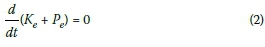
There are many analytical methods for calculating a structure's fundamental frequency, but very few of these methods can incorporate a varying section area, varying stiffness and lumped mass all together. Energy methods are of the few methods that can incorporate all the varying properties of the tower to calculate the fundamental frequency. The principle of conservation of energy forms the basis of all energy methods. The principle states that the total energy of a closed system will stay constant in the absence of losses such as friction, damping, etc. In practice there will always be energy losses, but these losses are negligibly small in many cases and thus an accurate answer can still be achieved by neglecting them (LaNier 2004). The total energy of a closed vibrating system can be categorised into potential energy (Pe) and kinetic energy (ke) and has the following property in time (t):
Rayleigh's method for rigid foundations
Rayleigh's energy method uses the conservation of energy principle to calculate the fundamental frequency of a structure. The kinetic energy of the system is the energy of the vibrating motion and is calculated from the velocity. The potential energy is given by the strain energy of the tower. The first step in Rayleigh's method is to assume a displacement function for the structure. The displacement function can then be used to calculate the kinetic and potential (strain) energy. The accuracy of the method largely depends on the accuracy of the assumed deflection function. A generic equation for the fundamental frequency of a beam is derived below:
Assuming harmonic vibration and that the displacement function for the structure is given by (Buchholdt & Nejad 2012):

where
Y(x) is the assumed deflection shape of the tower
ωis the angular frequency
αis the phase angle.
The kinetic energy of the beam is given by:
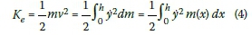
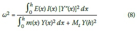
with y the first derivative of the displacement function, m(x) the section mass per metre at height x and h the height of the tower.
Accounting for the lumped turbine mass the maximum kinetic energy is given by:
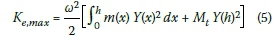
where Mtis the turbine mass.
The reinforced concrete section is considered a composite material. The moment of inertia for the section should thus be calculated using the transformed-section method.
The potential energy of the beam is the work done by deforming the beam. By assuming elastic deformation and neglecting the work done by shear force, the potential energy for the beam is given by:
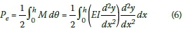
The maximum potential (strain) energy is given by:
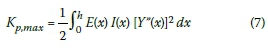
where E(x) is the Young's modulus for the transformed section at height x, I(x) is the moment of inertia for the transformed section at height x and Y"(x) is the second derivative of the displacement function.
According to the conservation of energy principle Ke,max= Pe,maxand thus the fundamental frequency is:
It is important to note that Rayleigh's method yields an upper-bound solution for the fundamental frequency of the tower. The assumed displacement function introduces additional constraints, which increase the stiffness of the system and thus leads to a slightly higher fundamental frequency than that of the real structure. There are various deflection curves available for cantilever beams - two of the common curves are given below (Buchholdt & Nejad 2012):
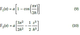
where a is a constant describing the maximum deflection of the tower; a is left as a constant throughout the frequency calculations.
Rayleigh's method for flexible foundations
Rayleigh's method discussed above does not make provision for the flexibility of the soil under the foundation. This effect can be accounted for by using a method proposed by Berger-Abam Engineers (LaNier 2004). The method involves separating the vibration frequencies into a rigid body base rotation frequency, rigid body base translation frequency and the tower flexure frequency. The different frequencies can then be combined with the following equation:
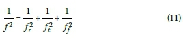
where
f is the combined tower frequency
fris the rigid body base rotation frequency
ftis the rigid body base translation frequency
ffis the tower flexure frequency calculated in the previous section of this paper (Rayleigh's method for rigid foundations).
The rigid body base rotation frequency can be calculated by defining a new deflection curve for the rigid body motion. The frequency can then be calculated with the same method used to calculate the flexural frequency in the previous section of this paper (Rayleigh's method for rigid foundations). The rigid body translation frequency can be calculated directly. The results are given below:
Base rotation
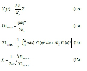
where b is a constant and Kris the rotation stiffness of the foundation.
Base translation
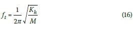
where Khis the translation stiffness of the foundation and M is the mass of the whole system.
The modified tower fundamental frequency is then given by:
RESULTS AND DISCUSSION
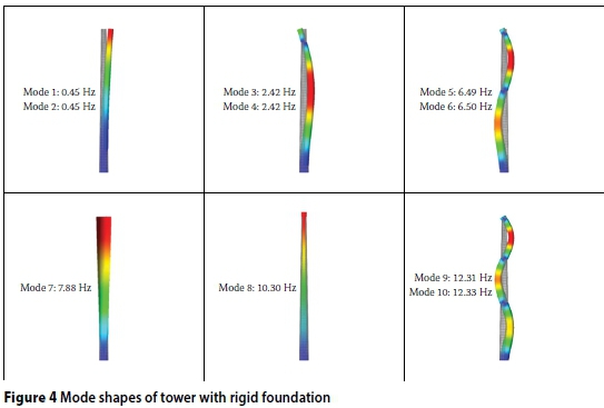
Rigid foundation
The first ten mode shapes for the tower obtained from the finite element analysis of the tower with a rigid foundation, are shown in Figure 4. The soil stiffness is not taken into account for this model and the tower is fully fixed at its base. The tower is symmetrical around the XY and ZY planes and thus certain mode shapes will occur twice at almost the same frequency.
The accuracy of Rayleigh's method and its sensitivity to the assumed deflection curve are calculated by comparing the fundamental frequency obtained by both approximate deflection curves (Equations 9 and 10) and the static deflection curve to the frequency obtained from the FEM. The static deflection curve refers to the normalised deflection obtained from the FEM under static wind loading. The results are given in Table 4.
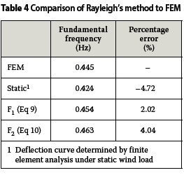
It is interesting that the approximate function F1 gives a more accurate answer than the static deflection function. All the functions do, however, approximate the frequency computed with the FEM within 5%, which in most cases will be sufficiently accurate.
Rigid foundation with concrete cracked
The formation of cracks in concrete reduces the stiffness of the concrete in tension. This can be captured numerically by performing an eigenvalue analysis once the cracks have formed (Diana 9.4.4 2012). The results of the Eigen value analysis, done while the serviceability limit state (SLS) wind loads are acting on the tower, are shown in Table 5.
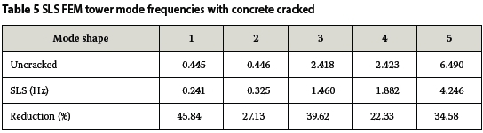
From the results it is clear that the fundamental frequency of the tower is significantly reduced by the formation of cracks in the concrete. The reduction causes the frequency to fall outside the working frequency of the tower and will thus cause the tower to resonate. It is interesting to note that the first mode frequency is reduced much more than the second mode frequency, although they have the same mode shape. The reason for this is that the first mode coincides with the deflection direction of the tower in the SLS. The second mode is perpendicular to the applied wind load. This causes less concrete to be cracked in the tension zone of mode two, thus increasing the stiffness in this direction.
Flexible foundation using FEM
The FEM with foundation that is schematised in Figure 4 is used to determine the mode frequencies of the tower supported on different soil types. The spring stiffness is changed according to the specific soil type being modelled. The results for various soil types are given in Table 6.
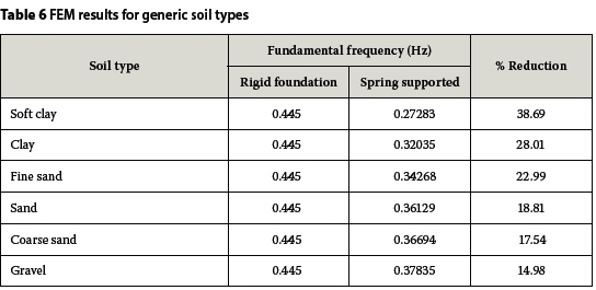
The percentage reduction in frequency given in Table 6 is quite severe. Wind turbine foundations are, however, not constructed on untreated soil. Extensive soil preparation is done before the foundation is constructed. The preparation can include various base layers, compacting techniques and even pile foundations if the soil stiffness is still undesirable. The analysis does, however, emphasise the importance of a detailed geotechnical survey to determine the soil stiffness, as an overestimation of the soil stiffness may cause severe vibrations and even resonance of the structure. As an alternative, if it is known that the foundation will influence the frequency, the tower's frequency has to be adjusted so that the combined frequency falls within the allowable operating frequency range.
Flexible foundation using Rayleigh's method
Rayleigh's method for flexible foundations is compared to the uncracked FEM results to determine the accuracy of this method. The results obtained by the modified Rayleigh's method for different soil types are given in Table 7.
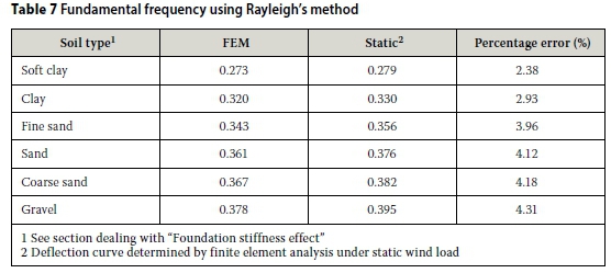
The static deflection curve gives the most accurate results and approximates the fundamental frequency within 5% of the FEM results for all the soil types. The method is therefore an excellent analytical method for determining the frequency of a tower with a flexible foundation.
CONCLUSION AND FUTURE RESEARCH
Concrete wind turbine towers play a vital role in ensuring the continual development of large-scale wind turbines. The lack of knowledge on the design of concrete wind turbine towers in SA gave rise to this research project. The goal of this paper was to investigate the dynamic behaviour of large concrete wind turbine towers and to highlight important factors influencing the dynamic behaviour of the tower.
The sensitivity analysis done on the fundamental frequency of the tower, emphasised the importance of modelling the actual structure and boundary conditions as accurately as possible when carrying out an eigenvalue analysis.
The fundamental frequency of the example tower is reduced by 46% after the tower has cracked. This reduction leads to the tower's frequency falling outside the working frequency of the turbine. It may be necessary to increase the percentage reinforcing to reduce cracking and ultimately reduce the stiffness reduction caused by cracking. It is important to note that the reduction in fundamental frequency is strongly dependent on the specific tower being modelled. Differences in height, reinforcing layout and level of loading may all affect the reduction in fundamental frequency.
The soil stiffness has a significant influence on the tower's natural frequency. The preparation of the soil under the foundation will thus strongly influence the dynamic behaviour of the tower. The soil sensitivity analysis highlighted the importance of a comprehensive geotechnical survey, as both underestimation and overestimation of the soil stiffness may lead to structural failure due to resonance.
Rayleigh's analytical method for calculating the fundamental frequency of the tower gives accurate results. The method calculated the frequency for both rigid and flexible foundations within 5% of the frequency computed by the FEM. The method is thus an excellent method for determining the geometry of the tower in the preliminary design stage.
It became clear, while doing this project, that the formation of cracks in the concrete can have a significant effect on the behaviour of the tower, and even make it difficult to predict the dynamic behaviour. Post-tensioned tower construction is suitable for dynamically loaded structures and should eliminate the formation of cracks in the concrete if the post-tension force is sufficiently large. This has the benefit that it is possible to accurately compute the fundamental frequency of the tower. The durability of the structure will also be greatly increased. These advantages of post-tensioned concrete constructions may justify the cost increase of the method.
REFERENCES
Buchholdt, H A, & Nejad, S E 2012. Structural Dynamics for Engineers. London: Institute of Civil Engineers, UK (ICE). [ Links ]
Diana 9.4.4 2012. Diana (DIsplacement ANAlyser) user's manual. In: Manie, J & Kikstra, W P (Eds.), Element Library, Chapter 9. Netherlands: TNO-DIANA. [ Links ]
DNV & Ris0 2002. Guidelines for the Design of Wind Turbines, 2nd ed. Denmark: Det Norske Veritas (DN V) and Ris0 National Laboratory. [ Links ]
Feenstra, P H, de Borste, R & Rots, J G 1993. A comparison of different crack models applied to plain and reinforced concrete. In: Van Mier, J G M, Rots, J G & Bakker A (Eds.), Fracture Processes in Concrete, Rocks and Ceramics, London: E & F Spon, pp 629-638. [ Links ]
FIB (International Federation for Structural Concrete) 2010. Model Code 2010. Switzerland: FIB. [ Links ]
Gazetas, G 1983. Analysis of machine foundation vibrations: State of the art. Soil Dynamics and Earthquake Engineering, 2(1): 2-43. [ Links ]
GWEC (Global Wind Energy Council) 2013. Global wind energy report. Brussels, Belgium: GWEC. [ Links ]
LaNier, M 2004. LWST Phase I. Project conceptual design study: Evaluation of design and construction approaches for economical hybrid steel/concrete wind turbine towers. Washington DC: National Renewable Energy Laboratory. [ Links ]
Harte, R, Van Zijl, G P A G 2007. Structural stability of concrete wind turbines and solar chimney towers exposed to dynamic wind action. Journal of Wind Engineering and Industrial Aerodynamics (JWEIA), 95 (9-11): 1079-1096. [ Links ]
Vestas Wind Systems 2011. Foundation Design Guidelines V80-V90-V100. Denmark: Vestas Wind Systems A/S. [ Links ]
 Correspondence:
WILLEM VAN ZYL
Structural Division
UWP Consulting
Unit 202, 2nd Floor
De Jonker Centre
Morkel Street
Stellenbosch 7600
South Africa
T: +27 (0)21 883 2788
E: willemvz@uwp.co.za
GIDEON VAN ZIJL
Department of Civil Engineering Stellenbosch
University Private Bag X1
Matieland 7602
South Africa
T: +27 (0)21 808 4436
E: gvanzijl@sun.ac.za

WILLEM VAN ZYL, who is a grad uate member of SAICE, obtained his Bachelor's (2012) degree and his Master's (2014) (cum laude) in Civil Engineering from Stellenbosch University. This paper is a condensed version of his Master's thesis, which focuses on the structural design of concrete wind turbine support structures in southern Africa.

PROF GIDEON VAN ZIJL Pr Eng is professor in structural engineering at Stellenbosch University. He obtained his Bachelor's (1986) and Master's (1990) degrees in Civil Engineering from Stellenbosch University, and his PhD (2000) from Delft University in the Netherlands. As Director of the Centre for Development of Sustainable Infrastructure, his research interests are structural and computational mechanics, including the development, characterisation, and constitutive and durability modelling of advanced construction materials.

