


Servicios Personalizados
Articulo
 Inglés (pdf)
 Articulo en XML
 Referencias del artículo
Indicadores

Links relacionados
-
 Citado por Google
 -
 Similares en Google
Compartir

 Permalink
Journal of the South African Institution of Civil Engineering
versión On-line ISSN 2309-8775
versión impresa ISSN 1021-2019
J. S. Afr. Inst. Civ. Eng. vol.57 no.4 Midrand oct./dic. 2015
http://dx.doi.org/10.17159/2309-8775/2015/v57n4a4
TECHNICAL PAPER
Design aspects of concrete towers for wind turbines
C von der Haar; S Marx
ABSTRACT
All over the world an increase in the use of renewable energy sources is being sought, and here the utilisation of wind energy plays an important role. Germany currently represents one of the world's largest markets for wind energy. At the end of 2013, nearly 24 000 onshore wind turbines with a total output of approximately 34 000 MW had been installed in Germany. Hub heights of up to 140 m and outputs of 3 to 4 MW are now no longer unusual features of new onshore wind turbines.
The focus of this paper is on concrete support structures for wind turbines. Different concrete tower concepts are presented, and the influence of the construction method on the design and verification processes is described. In particular, the text deals with the eigenfrequency analysis, as well as the bearing, shear and torsional resistances of concrete towers. The differences between cast-in-place and precast towers are listed.
INTRODUCTION
The utilisation of renewable energy technologies and the generation of clean energy are worldwide trends. Due to increasing prices and limited supplies of fossil fuels, as well as the rising desire of the population for a sustainable use of natural resources, renewable energy technologies are becoming more economical and more and more important for image-conscious energy companies. Sun, water, wind and biomass are promising sources for the generation of renewable energy. Wind energy in particular is considered an energy source with very high potential. Today wind turbines are being planned and realised at onshore and offshore locations worldwide. New prototypes have a rated power of 10 MW, hub heights of 140 m, and rotor diameters of up to 190 m.
In Germany, the generation of wind energy began 30 to 40 years ago. In the year 1990, the average rated power of a new onshore wind turbine was about 200 KW, and the average hub height was about 30 m. These towers were almost exclusively built as lattice or tubular steel structures. In subsequent years wind towers and rotor diameters increased in size, and thus the rated power of wind turbines also increased rapidly. The advantage of taller wind turbines is that they are exposed to a higher average wind speed and a more constant wind profile over the height of the rotor. The maximum power of a wind turbine can be calculated as per Equation 1, which is derived from the law of the transformation of energy:
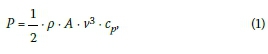
where ρis the density of the air, A is the area of the rotor, cpis a power coefficient and v is the wind speed. Because the wind speed is a third-term factor it is obvious that taller wind turbines have higher efficiency potential based on the cubed wind speed than shorter ones. In the year 2013 the average rated power of new onshore wind turbines was around 2.6 MW. The average hub height of these wind turbines was 118 m, and 33% of the new wind turbines had hub heights of 120 m to 140 m. Therefore, the average rated power of newly installed onshore wind turbines increased thirteen-fold between 1990 and 2013 (Agora 2013; WindGuard 2013; Fraunhofer IWES 2014).
However, consequences of this development are also higher loads and stresses, as well as bigger dimensions of the support structures. The sizes of the larger steel sections, which were originally transported by heavy-load vehicles, started to exceed the road transport limitations, especially the clearance height of bridges, so that concrete towers became a more attractive alternative for the latest wind turbine support structures.
The focus of this paper is on concrete support structures of wind turbines. Different concrete tower concepts are presented, and the influence of the construction method on the design and verification processes is described. The text deals predominantly with German developments and with guidelines and standards for wind turbines with capacities of 3 to 4 MW, which represent the current upper range of new onshore wind turbines.
CONSTRUCTION TYPES
The towers of the first wind turbines built in Germany were almost exclusively constructed as lattice or tubular steel structures, while concrete towers were rarely built. Due to the demand for higher and more powerful wind turbines, hybrid towers, consisting of a lower part built in concrete and an upper part built as a tubular steel section, have in recent years been shown to be very economical solutions for multi-megawatt class wind turbines. This is how concrete towers entered the limelight for designers and manufactures. The length ratio of the concrete part and the steel part mainly depends on the requirements of the natural oscillation behaviour of the tower and on economic aspects, which in turn depend predominantly on the manufacturing and material costs.
The concrete shafts of these hybrid towers consist of in-situ or precast concrete with internal or external prestressing.
Cast-in-place concrete towers
Cast-in-place towers can be built economically by using climbing or sliding formwork. Sliding formwork has the advantage of allowing a continuous and fast construction progress. However, the concrete mixture has to be adjusted carefully to the sliding velocity and the weather conditions, otherwise the sliding process has a high potential for causing horizontal cracks in the finished shaft wall.
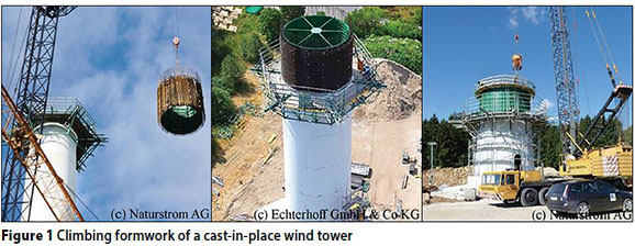
Construction with climbing formwork has the advantage of being done in sections, and expensive night and weekend shifts are not required. In Germany climbing formwork by crane is generally used. The formwork exists of both an inner and outer shell, which are adjustable to the required diameters. The construction process is as follows: At the construction site the inner and outer form-work are adjusted to the required diameters of the tower. Subsequently, the reinforcement and additional required parts are attached to the inner formwork. In this construction step the reinforcing bars that extend to the next segment protrude above the formwork. Next, the inner formwork with its reinforcement is lifted by crane to the top of the tower (Figure 1 left), and is placed in its position (Figure 1 middle). Then the outer formwork is lifted to the top of the tower and placed over the inner formwork and its reinforcement bars, after which the concrete is poured (Figure 1 right). The formwork should be constructed so that it can withstand the weight of the fresh concrete without requiring any additional anchors. Anchors are needed only for attaching the formwork and the working platforms. The following day the formwork is removed and the next section is constructed. It is important to make sure that the diameter of the inner formwork can be reduced so it can be lifted easily from the inside of the conical tower shaft. Provided that sufficient formworks are available, one section of approximately 4 m height can be completed in one day. Therefore, the concrete strength and anchor points for the suspension of the form-work and the working platforms have to be designed so that the structure can withstand the additional load on the next day.
Due to the nature of this construction process the tower shaft is a monolithic construction with continuous reinforcement bars. It is usually externally post-tensioned; therefore no ducts for tendons have to be installed, which simplifies the construction process.
Precast concrete towers
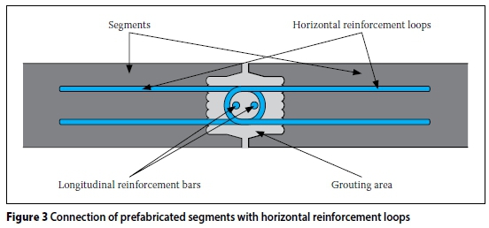
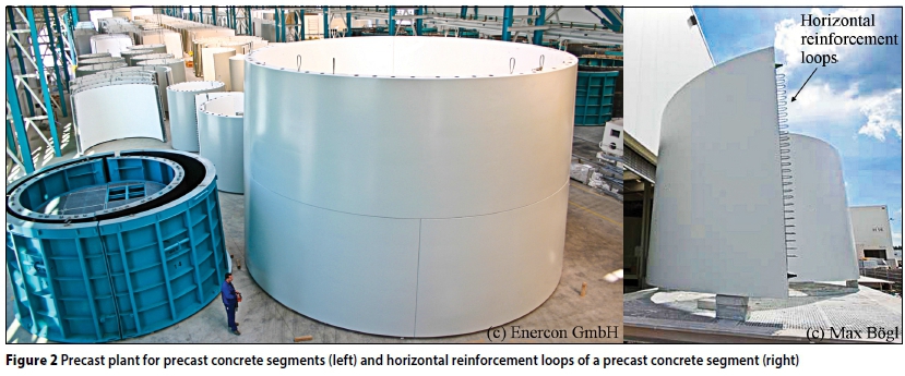
Prefabricated concrete units are assembled by crane on top of one another and tied together with post-tensioning tendons. The concrete units are manufactured in precast plants so that high quality and short processing times can be achieved (Figure 2 left). The concrete units are transported by heavy-load vehicles to the construction site. Smaller units are transported as whole rings, while bigger ones are divided into two or three segments so as to not exceed the transportation size limitations. At the construction site the segments are placed in front of one another. Horizontal reinforcement loops are positioned so that they overlap in the grouting areas (Figure 2 right; Figure 3). Longitudinal reinforcement bars are inserted between the reinforcement loops. Subsequently the grouting area is filled with flowable grout. The vertical joints of this construction method can be designed as reinforced joints, using the relevant design codes.
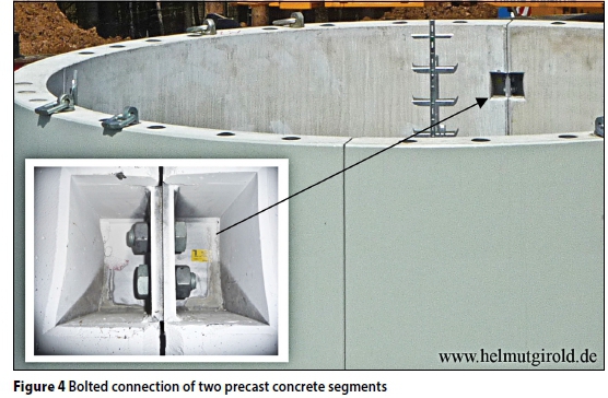
An alternative connection method is depicted in Figure 4. Here the segments are joined by bolts; therefore special openings have to be provided in the segments.
During construction, each installed element should be rotated by 90° (for two segments per unit) or 60° (for three segments per unit) with respect to the previous one so that the vertical joints of the segments are not positioned directly above each other.
The connection types of the horizontal joints between the segments vary from manufacturer to manufacturer. The wind owers built by Enercon are constructed with wet joints. Before assembly, a mortar layer is placed on the surface of the element. The following element is set into the wet mortar, squeezing the surplus mortar out of the joint. The elements are thus attached to each other and the mortar compensates for any uneven-ness of the contact surfaces. Finally the elements are tied together with internal post-tensioning tendons. The ducts of the tendons can be seen in Figure 4. The mortar must not enter the post-tensioning ducts. Generally the mortar has a higher tensile strength than the concrete. Therefore bending cracks caused by wind actions will appear in the concrete elements themselves and not in the contact areas between concrete and mortar. The resulting crack surfaces will be rough and crack keying will take place so that the horizontal joint can be designed like a common prestressed concrete beam.
For the HybridTower by Max Bögl an alternative system is used. The elements are placed on top of each other without a mortar layer between them. To compensate for any unevenness of the contact surfaces they are polished by a grinding machine. The advantage of this connection principle is its fast and simple construction progress, which is also independent of the weather conditions at the construction site. However, the shear stresses resulting from the tor-sional moments and the shear forces have to be transferred by friction across these horizontal polished joints. The Max Bögl HybridTowers are externally post-tensioned, and no further tensile material or joining element is placed between the concrete elements. This requires special verification methods, which will be presented in the section entitled "Shear and torsional resistance of horizontal joints".
Foundation
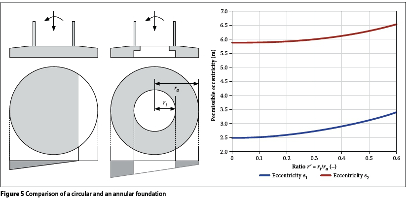
The foundation of onshore wind towers are predominantly designed as circular or annular foundations. The geometry of circular foundations is very simple, whereas annular foundations require less material and exhibit higher geotechnical stability. According to DIBt (2012), the permissible gap between the foundation and the soil under different loading conditions is limited. For quasi-permanent load combinations no gap is permitted, and for unfactored extreme loads a maximum gap area of one half of the foundation area is acceptable (plan view).
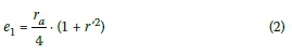
The improved stability of annular foundations with respect to circular foundations, according to the above-mentioned requirements of DIBT (2012), can be expressed by the following permissible eccentricities: e1which is defined as the ratio of the maximum bending moment and the normal force without an opening, and which is defined as the ratio of the maximum bending moment and the normal force with an opening up to a maximum of one half of the foundation area.
To explain the eccentricities, a numerical example is presented. The outer radius of the foundation is ra= 10 m, the inner radius varies between rt= 0 m (circular foundation r' = ri/ra= 0.0) and ri= 6 m (annular foundation r' = r/ra= 0.6). For the annular foundation, the permissible eccentricity e1 increases from 2.5 m to 3.4 m, and the eccentricity e2 increases from 5.9 m to 6.5 m with respect to the circular foundation (Figure 5). It can be seen that the bending capacity without and with opening of one half of the annular foundation area is 36% and 10% larger, respectively, than that of the circular foundation. However, a more slender annular foundation (r'-1) also results in bigger soil stresses, which limit the slenderness of the annular foundation. The permissible eccentricities e1and e2can be calculated with Equations 2 and 3:
EIGENFREQUENCIES
The extreme and operating loads of a wind turbine are calculated with total dynamic load simulations. In these simulations wind gusts, sudden changes of wind direction, starting, operating and stopping procedures of the turbine, as well as the dynamic behaviour of the whole system consisting of foundation, tower and turbine, are considered. The stiffness of the system has a direct influence on the resulting internal forces. To avoid dynamic amplifications, the eigenfrequencies of the structure should not be within the range of the excitation frequencies of the turbine. The excitation frequencies are:
1. Periodic excitation at the frequency of the rotational speed of the rotor (1P excitation), for example due to imbalances
2. Periodic excitation at the frequency of three times the rotational speed of the rotor by blade passing (3P excitation)
3. Whole-number multiples of the rotor frequency.
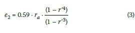
The nominal rotor speed of a 3 MW class wind turbine usually lies between 6 and 13 rpm. This means that the rotational frequency of the rotor lies between 0.1 and 0.22 Hz, and the blade passing frequency is three times higher, between 0.3 and 0.65 Hz for three blades. According to DIBt (2012) the excitation frequencies and the eigenfrequencies of the structure should not be within ±5% of each other. Additionally, calculation uncertainties should be considered by adding a safety of ±5% (see DIBt 2012). By this a safety margin of 1.05 χ 1.05 = 1.1025 - 10% is achieved. Considering this safety margin, the permissible range of natural frequencies can be shown with the Campbell diagram. According to this diagram, the permissible range of eigenfrequencies lies between 0.24 and 0.27 Hz for the assumed rotor speed of 6 to 13 rpm (Figure 6).
A wind tower design for which the first eigenfrequency lies below the blade passing frequency (3P) and above the rotor frequency (1P) is called "soft-stiff". A design where the eigenfrequency of the structure lies above the blade passing frequency (3P) is called "stiff-stiff". Such stiff designs, however, are uneconomical and require large quantities of material. If the first eigenfrequency is lower than the rotor frequency (1P), the design is called "soft-soft". With this type of design very slender support structures can be created, for which the fatigue resistance has to be checked very carefully (see Grünberg & Göhlmann 2013).
Influence of the geometry and the material on the eigenfrequency
The height of the tower and the weight of the turbine are set by the turbine manufacturer; therefore designers only have limited options for shifting the eigenfrequencies of the structure into the permissible range defined by the Campbell diagram. Today most simulation software can determine the eigenfrequencies of a wind turbine with high reliability. Alternative calculations based on energy methods also yield good results (see Grünberg & Göhlmann 2013).
The main attribute influencing the eigenfrequency of the tower is its diameter. The stiffness of the tower, and hence the tower frequency, increase with its diameter. Eigenfrequency analyses for different tower diameters were performed for a wind tower with a hub height of 140 m and a turbine mass of 300 tons. The outer diameter at the top of the tower was chosen to be 3.0 m; this dimension is usually defined by the geometry of the nacelle. The outer diameter at 90 m above the ground was assumed to be 4.5 m to guarantee blade passing. The diameter at the base of the tower was varied between D = 8.0 m and D = 14.0 m. The diameter was assumed to decrease linearly between the given points (Figure 7 right). The results are based on concrete of strength class C60/75 according to EN 1992-1-1 (2010) with an elastic modulus of Ecm= 39 100 N/mm2. The adopted specific weight of the concrete was γ= 25 kN/m3, and it was not increased to consider additional installation parts such as leaders and so on. The thickness of the shaft wall in these analyses was varied between t = 0.20 m and t = 0.40 m. As depicted in Figure 7 and mentioned before, the diameter has a large influence on the eigenfrequency of the tower. The shaft thickness influences the eigenfrequency as well, but the effect is not as dominant, because the stiffness increase due to a larger shaft thickness is offset by the resulting higher mass of the tower.
The elastic modulus of Ecm= 39 100 N/ mm2 is only a mean value for concrete of the chosen strength. The actual value can vary depending on the used mineral aggregate, the concrete composition, as well as how and how long the concrete is cured. It is recommended to test the elastic modulus of the used concrete in the preliminary design stages to get realistic values for the calculations. Alternatively the eigenfrequency analysis should be performed for lower and upper values of the elastic modulus of the concrete.
In this context the cracking of the structure and the resulting stiffness reduction of the tower also have to be considered. But the dynamic amplification due to wind actions and dynamic interactions with the rotor, and the blade excitation frequencies are particularly important for operating conditions, and therefore also for fatigue loads and frequent load cases. It follows that the prestressing of the tower should be designed so that no cracks can form even for those load cases.
The elastic modulus Ecmaccording to EN 1992-1-1 (2010) is generally defined as the secant modulus of the concrete. Its intersection point with the stress-strain curve is at 40% of the concrete strength. The compres-sive stress of the concrete is limited to 60% of the concrete strength under rare load combinations according to DIBt (2012). Therefore, the stresses caused by frequent actions are in the defining range of the modulus of elasticity; hence it can be used for eigenfrequency analyses without any further adjustments.
Influence of the foundation
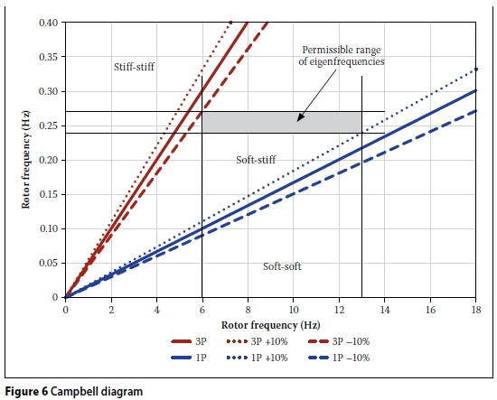
In the previous calculation the base of the tower was fixed against rotational, horizontal and vertical displacements. This assumption is incorrect; the stiffness of the foundation and the soil have to be considered in the eigenfrequency analyses. The guideline DIBt (2012) refers to DGGT (2002) for geotechnical issues. According to this publication, the rotational, horizontal and vertical stiffness can be calculated using Equations 4 to 7 for circular foundations:
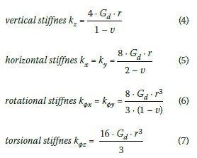
where Gdis the dynamic shear modulus of the soil, r is the radius of the foundation and υis the Poisson's ratio of the soil. In DGGT (2002) ranges of values for these parameters in dependence of the soil conditions are given.
BEARING CAPACITY AND SECOND ORDER THEORY
The design process for concrete towers generally follows relevant design codes such as EN 1992-1-1 (2010). The internal forces in the tower are usually calculated by the turbine manufacturer using total dynamic simulations. These calculations are typically performed as geometric nonlinear calculations that assume the concrete to behave in a linearly elastic manner. This means that the nonlinear behaviour of the concrete and the stiffness reduction due to crack formation have to be considered separately, especially for the ultimate limit state. Considering these issues yields higher deformations and additional second order bending moments. The joints of the precast towers also influence the deformations and additional bending moments, as will be shown in the following paragraphs.
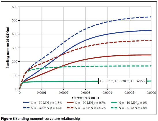
Crack formation and the physical non-linearity of the concrete can be considered in bending moment-curvature relationships, or Μ-κ-curves. The Μ-κ-curves for annular cross sections can be calculated according to the approach presented by Grünberg and Göhlmann (2013).
Figure 8 shows the Μ-κ-curves for an annular cross section. The outer diameter is 12 m and the shaft thickness is 30 cm. A concrete of strength class C60/75 according to EN 1992-1-1 (2010) is assumed. The calculations are performed for a normal force of N = -30 MN (dashed lines) and N = -10 MN (continuous lines). The reinforcement ratio ρ, which is defined as the ratio of the cross-sectional area of the reinforcement and the cross-sectional area of the concrete, varies between 0%, 0.7% and 1.3%. A ratio of ρ= 1.3% corresponds to a reinforcement ratio of 39 cm2/m respectively, being 19.5 cm2/m in the outer and inner sides of the shaft wall. A value of ρ= 0% represents the joint of a precast tower with external post-tensioning. Tension stiffening is neglected in these calculations. This assumes the design of concrete towers on the safe side. The Μ-κ-curves of the reinforced cross sections (blue and red lines) show two characteristic kinks in the curve, the first of which represents the transition from the uncracked to the cracked state. The second kink represents the point where first reinforcement bars start yielding. The kinks are less present than those of rectangular cross sections with only one layer of reinforcement. The reasons for this are the annular shape and the uniformly distributed reinforcement around the circumference. The diagram shows that the bending resistance of a reinforced cross section increases with the reinforcement ratio and the compressive force for a given curvature. The unreinforced cross sections (green lines), which represent the joints between two precast elements, show only one change of slope at the point where a gap between the elements opens. Beyond this point the bending capacity is nearly constant. The bending capacity is solely dependent on the compressive force.
With the Μ-κ-curves and the internal bending moments the curvature κover the tower height can be determined. By integrating the curvature κthe rotation φis obtained, and by integrating the rotation φthe deformation w of the concrete tower under consideration of crack formation and stiffness reduction can be calculated. The deformation w multiplied with the vertical loads over the tower height results in additional second order bending moments. Figure 9 shows the results for a 140 m high prestressed concrete tower as shown in Figure 7 (right). The calculations are performed for a continuously reinforced monolithic tower and a precast tower with a vertical joint distance of 5 m. The chosen concrete strength class is C60/75, and the tower is prestressed with 28 tendons with a prestressing force of approximately 3 MN each. At the beginning of the calculation the Μ-κ-curves have to be determined under consideration of varying dimensions, normal forces and reinforcement ratios over the tower height. Based on these curves and a given bending moment according to first order theory, the curvature over tower height is obtained. By double integration of the curvature the deflection of the tower is determined. The additional second order bending moment is determined by multiplying the vertical loads and the deflections. The following iteration step starts again with the determination of the curvature for the sum of bending moment according to first order theory and the additional second order bending moment. The iteration is done until the deformations converge.
The curvature of the monolithic tower shows a continuous progression along the entire hub height. In contrast the curvature of the precast tower shows a bump at each horizontal joint. The bumps are a result of the lower bending resistance at each joint with respect to the reinforced elements (see Figure 8). This leads to additional rotations and as a consequence to larger deflections and a bigger bending moment. The deflection at the top of the tower increases from 3.12 m for the monolithic tower to 3.89 m for the precast tower.
Precast towers with external post-tensioning exhibit a lower bending resistance in the horizontal joints than continuously reinforced monolithic towers or precast towers with internal post-tensioning. Therefore, the applied post-tensioning forces are usually higher for this type of tower.
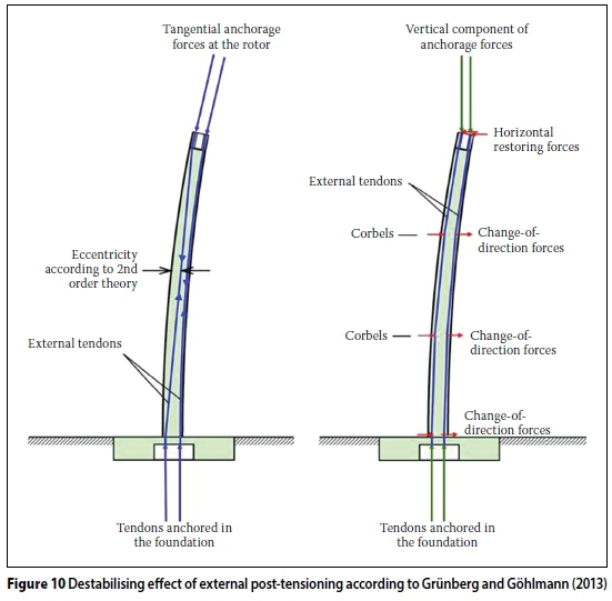
For towers with external post-tensioning the eccentricity between the deformed shaft wall and the tendons introduces additional destabilising bending moments, which have to be considered in the calculations. These destabilising bending moments can be reduced by installing corbels on the inside of the tower, which can be positioned at the third points of the tower height as depicted in Figure 10.
SHEAR AND TORSIONAL RESISTANCE OF HORIZONTAL JOINTS
The different construction methods for the horizontal joints must be treated differently when verifying the designs. The joint of the Enercon tower, for example, can be treated like a horizontal crack according to the relevant design codes. The shear forces and torsional moments can be determined with the widely known truss models suggested in EN 1992-1-1 (2010).
The joints of the Max Bögl tower are unreinforced joints so that the shear forces and torsional moments have to be transferred between the elements by friction. For design verification it is important to distinguish between joints that are completely compressed and opening joints. If the joints are completely compressed a Bredt shear flow can be assumed. If they are opened the torsional capacity must be determined according to the approach by St Venant (Wriggers et al 2005). As both approaches are only valid for thin-walled structures, this assumption is not correct for concrete towers. Additionally, the approach by St Venant assumes free warping of the cross section. Further investigations are required to solve these problems.
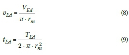
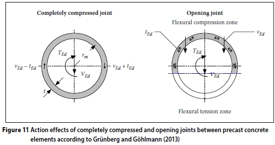
For completely compressed joints the action effects in the joints in the circumferential direction can be determined as per Equations 8 and 9:
The listed variables are defined in Figure 11. The shear resistance of a joint can be calculated according to EN 1992-1-1 (2010):
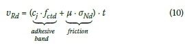
The adhesive bond must be neglected for non-grouted joints and for dynamic actions. The frictional part depends on the frictional coefficient μand the mean compressive stressσΜά.
The design check can be performed using Equation 11:
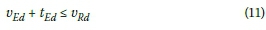
Neither the DIBt (2012) guideline nor the EN 1992-1-1 (2010) regulates the opening of joints. But, as mentioned before, crack formation of the reinforced elements should be prevented under fatigue loads and frequent load combinations. According to this the joints also should not open under these load combinations. Therefore, the opening of the joints and any associated reduction in stiffness must not be considered for the eigenfre-quency analyses and load simulations.
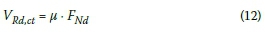
Under higher load cases, and especially the ultimate limit state, an opening has to be considered. The resultant shear force that can be accommodated by the area of the flexural compression zone is:
The torsional moment must be resisted solely by the St Venant torsional resistance:
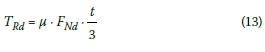
Referring to EN 1992-1-1 (2010) paragraph 6.3.2(5) the following linear interaction can be assumed for the combined analysis of the ultimate capacity:
CONCLUSION
The focus of this paper is on concrete support structures of wind turbines. Different concrete tower concepts were presented, and the impact of different construction methods on the design and verification process was explained. This article also deals with eigenfrequency analysis, and especially the bearing, shear and torsional resistances of the joints of precast concrete towers.
Precast concrete towers should be designed so that no cracks can form under fatigue loads and frequent load cases. Therefore, any associated reduction in stiffness must not be considered for the eigen-frequency analyses and load simulations. For higher load cases, and especially for the ultimate limit state, crack formation and the resulting stiffness reduction of the tower have to be considered in the design process. They lead to additional deformations and second order bending moments.
The advantage of precast concrete towers is a fast construction process on site. But the rotational stiffness at each horizontal joint is lower with respect to the reinforced concrete elements. This leads to additional rotations, larger deflections and bigger bending moments according to second order theory.
REFERENCES
Agora Energiewende 2013. Entwicklung der Windenergie in Deutschland - Eine Beschreibung von aktuellen und zukünftigen Trends und Charakteristika derEinspeisung von Windenergieanlagen [Development of wind energy in Germany: A description of present and future trends and characteristics of the power supply of wind turbines], [ Links ] Brief study. Berlin, Germany: Agora.
DIBt (Deutsches Institut für Bautechnik) 2012. Richtlinie für Windenergieanlagen - Einwirkungen und Standsicherheitsnachweise für Turm und Gründung. [ Links ] [Guidelines for wind turbines - Effects and structural safety tests for the tower and foundation]. Berlin, Germany: German Guideline.
DGGT (Deutsche Gesellschaft für Geotechnik) (German Geotechnical Society) 2002. Empfehlungen des Arbeitskreises Baugrunddynamik (Recommendations of Soil Dynamics Working Group). [ Links ]
EN (European Standard) 1992. EN 1992-1-1 2010. Eurocode 2: Design of concrete structures. Part 1-1: General rules and rules for buildings. Brussels, Belgium: European Committee for Standardization (CEN). [ Links ]
Fraunhofer IWES 2014. Windenergie report Deutschland 2013 [Wind energy report for Germany 2013]. [ Links ] Kassel, Germany: Fraunhofer-Institut für Windenergie und Energiesystemtechnik.
Grünberg, J & Göhlmann, J 2013. Concrete Structures for Wind Turbines. Berlin, Germany: Wilhelm Ernst & Sohn. [ Links ]
WindGuard 2013. Status des Windenergieausbaus an Land in Deutschland [Status of the progress in wind energy on land]. [ Links ] Varel, Germany: Deutsche WindGuard GmbH.
Wriggers, P, Nackenhorst, U, Beuermann, S, Spiess, H & Löhnert, S 2005. Technische Mechanik Kompakt. Stuttgart, Germany: Teubner. [ Links ]
 Correspondence:
CHRISTOPH VON DER HAAR
Institute of Concrete Construction
Leibniz University Hanover
Appelstrasse 9a 30167
Hannover
Germany
T: +49 511 762 1 7461
E: vonderhaar@ifma.uni-hannover.de
STEFFEN MARX
Institute of Concrete Construction
Leibniz University Hanover
Appelstrasse 9a
30167 Hannover
Germany
T: +49 511 762 3352
E: marx@ifma.uni-hannover.de

CHRISTOPH VON DER HAAR graduated with a degree in civil engineering in 2009 at Leibniz University Hanover. He started working as planning engineer for onshore wind turbines and bridge structures at an engineering consultant. Presently he is engaged at the Institute of Concrete Construction at the Leibniz University Hanover, and is studying towards his PhD. He is actively involved in the field of fatigue design of concrete structures for onshore and offshore wind turbines.

PROF STEFFEN MARX has been Managing Director at the Institute of Concrete Construction at Leibniz University Hanover since 2011. He mainly works in the research field of dynamically loaded concrete structures as wind turbine towers or high-speed railway bridges. His institute operates unique testing facilities for large-scale specimens to investigate them under static, dynamic and fatigue loads. Besides his research work at the university, he is associated with the engineering consultants Marx Krontal.

