


Servicios Personalizados
Articulo
 Inglés (pdf)
 Articulo en XML
 Referencias del artículo
Indicadores

Links relacionados
-
 Citado por Google
 -
 Similares en Google
Compartir

 Permalink
Journal of the South African Institution of Civil Engineering
versión On-line ISSN 2309-8775
versión impresa ISSN 1021-2019
J. S. Afr. Inst. Civ. Eng. vol.57 no.3 Midrand sep. 2015
http://dx.doi.org/10.17159/2309-8775/2015/V57N3A7
TECHNICAL PAPER
Investigating the bottom free surface nappe (ogee profile) across a sharp-crested weir caused by the flow in an asymmetrical approach channel
S J van Vuuren; G L Coetzee; C P R Roberts
ABSTRACT
The shape of an ogee spillway is based on the shape of the lower nappe of water flowing over an aerated sharp-crested weir. At the design discharge, this shape minimises the possibility of sub-atmospheric pressure occurring on the spillway and maximises the discharge across the spillway. The formulae that are currently in use to approximate the ogee profile consider only two-dimensional flow parameters, being the depth of flow over the spillway crest, the inclination of the upstream wall face, and the pool depth upstream of the spillway. The current formulae for the ogee shape, does not consider the influence of three-dimensional flow. The most significant three-dimensional flow parameters that could affect the shape of the lower nappe are the flow velocity distribution upstream of the spillway, the orientation or angle of the water approaching the spillway, the asymmetrical cross-section of the approach channel, and the curvature of the dam wall. This paper reflects the influence of asymmetrical flow in the approach channel. The investigation was based on a physical model constructed at the Department of Water and Sanitation (DWS). The inclination of the model's sidewalls of the upstream approach channel was varied to cause a change in the symmetricity, while the lower nappe profile was routinely measured. It was found that the flow in the asymmetrical approach channel caused a variation from the theoretical estimated ogee profile. A comparison between the measured nappe profile and the currently used formulae was investigated. It can be concluded that the symmetricity of the approach channel influences the shape of the bottom nappe, which differs from the shape as proposed by the current ogee formulae. It is recommended that three-dimensional flow should be examined when designing an ogee spillway.
Keywords: asymmetrical, cavitation, nappe, ogee profile, physical model, sharp-crested weir
LIST OF SYMBOLS
Al approach channel cross-sectional area measured from the centreline of the spillway's crest to the left bank (m2)
At total approach channel cross-sectional area (m2)
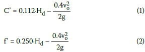
C' vertical displacement of the turning point measured at the lower nappe of the ogee profile (m)
f' horizontal displacement of the turning point measured on the lower nappe of the ogee profile (m)
Ha velocity head (m)
Hd measured water depth upstream from the crest of the sharp-crested weir, relative to the crest (m)
He total head (sum of Hd and Ha) (m)
Ho design head of ogee spillway (He - C') (m)
P upstream wall depth of the weir (m)
Tp turning point (apex position) on lower nappe of the ogee profile
Sf symmetricity factor of the approach channel
vo mean velocity in the approach channel (m/s)
INTRODUCTION
The ogee spillway relationship (USBR 1987; Hager 1987) is used to define the geometric profile of the spillway section of a dam or hydraulic structure. The ogee relationship describes the bottom nappe associated with the flow over a sharp-crested weir. The current relationship accommodates the influence of the unit discharge, the angle of inclination of the upstream wall face, as well as the relationship of upstream pool depth to the total upstream energy at the apex of the structure.
In cases where the discharge flow rate exceeds the design flow rate, the nappe detaches from the surface of the spillway and a sub-atmospheric pressure region is generated that may lead to cavitation (Savage & Johnson 2001; Momber 2000). Cavitation usually occurs during a unit discharge, in excess of the design head, where the surface pressure can be reduced at positions along the spillway to sub-atmospheric pressure. This may cause the formation of vapour cavities. Vapour cavities may also be formed on the spillway where an irregularity in the surface exists. The vapour cavities (also referred to as miniscule air bubbles) will progress along the flow path due to the high flow velocity on the spillway to a region downstream where sufficient pressure is available that will lead to the collapse of the air vacuum. This generates localised high pressures. Should these vapour cavities collapse near the spillway structure, there will be some superficial damage to the spillway's surface where the vapour bubble has collapsed. This cavitation damage can ultimately result in substantial erosion and, if ignored, will subsequently cause failures of the spillway chute. Minute cracks, offsets and increased surface roughness intensify this cavitation process. The extent of cavitation damage is a function of the cavitation indices at key locations on the spillway chute and the duration of flow over the spillway. This emphasises the need for a geometric, accurate and precise spillway profile to reduce the possibility of sub-atmospheric pressure formation (USACE 2009).
It is hypothesised that the geometric profile of the ogee spillway will be influenced by the following factors:
a. The asymmetrical cross-sectional approach channel upstream from the spillway
b. The relative orientation of the spillway with regard to the approaching flow
c. The curvature of the spillway in relation to the depth of the structure.
This study evaluated the existing ogee relationship, considering in particular the three-dimensional flow parameters resembling an asymmetrical approach channel.
The physical model was set up in accordance with ASTM Designation: D 5242-92 (Standard Test Method for Open-Channel Flow Measurement of Water with Thin-Plate Weirs (ASTM International 2001) and ISO 1438: Hydrometry - Open channel flow measurement using thin-plate weirs (ISO 2008). Froude similarity was selected with an undistorted scale of 1:10 for the physical model.
THEORETICAL CONSIDERATION
Research on the projectile movement of a free-falling jet of water revealed that the shape of the lower nappe of a jet of water flowing over a ventilated sharp-crested weir resembled the shape of an ogee spillway (Chow 1959; Hager 1987; Knapp et al 1970; Melsheimer & Murphy 1970; Ministry of Science and Technology 2007; Murphy 1973; USACE (a) 1987; USACE (b) 1987; USBR 1987; Wahl et al 2008). However, both the numerical relationships for the flow over a sharp-crested weir and the principle for the projectile movement of a free-falling jet of water describing this shape only consider the two-dimensional characteristics of the flow, namely the available energy (i.e. depth and velocity of water flowing over the spillway crest), the angle of inclination of the upstream wall face, and the height of the spillway above the natural ground level (USBR 1987; USCE 1970; Vischer & Hager 1999). This approximation of co-planar (two-dimensional) flow neglects the three-dimensional flow parameters which are occurring upstream of the spillway.
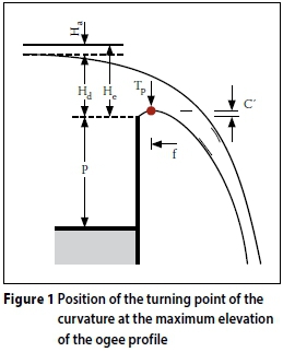
Research indicated that the vertical displacement of a flow particle at the crest's origin is equal to the vertical distance between the highest point of the nappe and the elevation of the ogee crest (Chow 1959). Figure 1 depicts this position, which is recognised as the turning point of the curvature (Tp). Rajaratnam et al (1968) (referenced by Vischer & Hager, Dam Hydraulics 1999) indicated that the vertical value of C' can be empirically estimated by Equation 1 and the horizontal distance (f) to this coordinate measured from the crest can be estimated by Equation 2. The experiments done by Rajaratnam et al (1968) were actually for a confined weir.
A wealth of literature sources are available on the approximation of the ogee profile for spillway design, and several endeavours have been made in developing a two-dimensional relationship that would be able to mathematically describe the most desirable shape of the ogee curve. These relationships exclude the asymmetricity of valleys and the asymmetricity of the topographical approach channels that influence the flow pattern and velocity distribution upstream of the spillway, leading to an insufficient design of the ogee spillway (Van Vuuren et al 2011).
Methods defining the geometry of the ogee spillway's crest are governed by the relative height of the structure, the available design head and upstream face slope of the spillway.
Other factors that should also be considered are the approach channel symmetricity, approach channel depth, orientation of the spillway relative to the flow path and the curvature (if applicable) of the hydraulic structure (Van Vuuren et al 2011). Literature reflects that in 1888 some of the first research was conducted to investigate the shape of the ogee profile. Ever since then the ogee spillway has been the most studied spillway geometry (Savage & Johnson 2001; Thandaveswara 2006).
The nappe-shaped profile is an ideal profile because at the design discharge, water flowing over the crest of the spillway always remains in contact with the surface of the spillway as it glides over it. Additionally, for the ogee shape, there will be no sub-atmospheric pressure regions that may develop on the spillway surface at the design discharge.
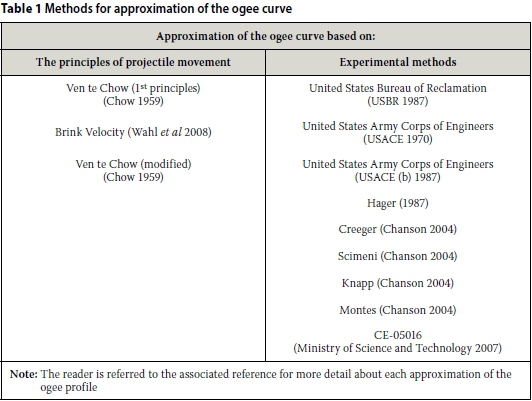
Some of the well-regarded approximations of the ogee profile are grouped according to the two categories shown in Table 1.
EXPERIMENTAL SETUP AND PROCEDURE
A physical model of a sharp-crested weir was constructed at the Department of Water Affairs and Sanitation's Hydraulic Laboratory, South Africa. The model provided the opportunity to:
■ provide the model with the correct dimensions and specifications in order to ensure that equations provided by the current literature are valid and that international credibility is achieved (ASTM International 2001; ISO 2008)
■ provide an undisturbed, uniform approach flow pattern across the weir, and vary the flow rate to enable the investigation of different stages versus flow rate scenarios, as well as measuring the stage of the approach flow accurately
■ measure the profile of the underlying nappe of water flowing over the sharp-crested weir.
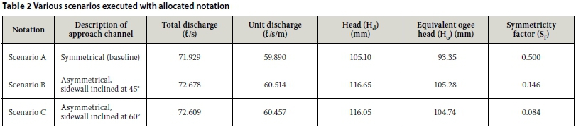
Three configurations of the physical model were investigated as reflected in Table 2, the first being the symmetrical layout with vertical sidewall, used as baseline reference for the other configuration. The other layouts comprised one having an inclined sidewall of 45° and the other an inclined sidewall of 60°. Six sheets of plywood were attached to steel frames and these were lowered into the approach channel of the physical model. The plywood sidewalls could vary between angles that ranged from 45° to 90°. This allowed the symmetricity of the approach channel to be changed to an asymmetrical approach channel with one sidewall either being sloped at 45° or 60°. The total length of the sidewall measured 7.2 m. The cross-sectional view of the variable approach channel is depicted in Figure 2.

The symmetrical approach channel, used as baseline scenario, was compared with the asymmetrical approach layouts that were conducted at various sidewall inclinations. The various scenarios executed were labelled as indicated in Table 2.
For each of the scenarios conducted a separate datasheet was set up in which the XYZ-coordinates of the lower nappe profile were populated. The stage depth measured in stilling columns by two OTT-point gauges was averaged and converted to the design head of an equivalent ogee structure. Equation 1 as defined by Rajaratnam et al (1968) was applied to calculate the equivalent ogee design head. The measured ogee profile for each of the scenarios was plotted in a three-dimensional XYZ surface plot against the theoretical ogee profile (USACE 1970).
RESULTS AND DISCUSSION
The experimental results produced by the asymmetrical approach channel generated seven ogee curves for each channel configuration, representing the three-dimensional shape of the asymmetrical bottom nappe. In the case of the symmetrical base line recordings, the ogee curve was measured at five increments along the crest of the sharp-crested weir, representing the three-dimensional shape of the symmetrical bottom nappe. These measured curves were representing the shape of the nappe that extends from the left boundary, centre and up to the right boundary of the nappe. The positions of the curves were chosen to ensure that all the scenarios could be analysed individually and later compared with the other scenarios. Each point measured was recorded as a three-dimensional XYZ coordinate.
These measurements were depicted in a two-dimensional XZ-plot in Figure 4, and were compared with the theoretical ogee profile by the USBR (1987), USACE (1970), Hager (1987) and Ministry of Science and Technology (CE-05016) (2007).
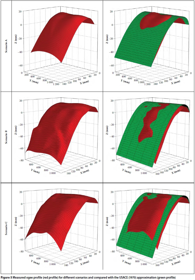
The measured ogee profile was plotted as a red surface in a three-dimensional XYZ-plot in Figure 5. Overlapping the measured ogee surface plot in Figure 5 is the theoretical ogee profile by the USACE (1970) depicted by the green surface.
Scenario A: Symmetrical approach channel (baseline)
It can be seen in the two-dimensional plot of scenario A that the ogee profile in the centre of the nappe was greater than those measured at the outer boundaries. This trend can be visualised in more detail in the final results in which the surface plot of the measured nappe was depicted in an XYZ plot. The reason for this outcome can be explained due to the fact that the ogee profile was measured for a symmetrical approach channel, and that an increased flow rate exists in the centre of the structure, resulting in minimal contraction and flow resistance at this location.
The result was that the theoretical approximations of the ogee profile tend to underestimate the measured ogee profile at the centre of the weir and overestimate the ogee profile at the boundaries where flow contraction and resistance was a maximum. Overestimation of the ogee profile is not as critical as underestimation. The overestimation of the ogee profile at the boundaries will simply imply that a positive hydrostatic pressure is present in these regions on the spillway. However, underestimating the ogee profile may cause a more detrimental effect, which may lead to cavitation of the surface of the spillway if significant sub-atmospheric pressures are experienced. Long-term exposure to extensive sub-atmospheric conditions may cause failure of the spillway structure.
Scenario B: Asymmetrical approach channel with sidewall inclined at 45°
In the two-dimensional plot of scenario B it was noticed that the ogee profile was greater toward the side of the inclined sidewall, unlike in scenario A where the greatest ogee profile occurred in the centre of the flow, due to the symmetricity of the approach channel. The greatest ogee profile tends to lie between the 600 mm and 800 mm measuring location. The inclined sidewall was installed to the right of the approach channel. The centreline tends to be moved off-centre in the direction where the inclined sidewall had been installed.
The result was that the theoretical approximations of the ogee profile tend to underestimate the measured ogee profile between the 600 mm and 800 mm mark measured along the crest, and again overestimate the ogee profile at the boundaries similar to the symmetrical approach channel layout.
Scenario C: Asymmetrical approach channel with sidewall inclined at 60°
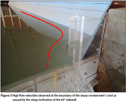
Similar to scenario B the two-dimensional plot of scenario C reflected that the ogee profile was greater towards the side of the inclined sidewall. The greatest ogee profile tends to lie at the 800 mm measuring location. This indicated that the ogee nappe was moved off-centre even more than in the case when the inclination of the sidewall was 45°. This 60° angle sidewall was steep and extended closely to the boundary of the 1 200 mm mark of the sharp-crested weir so that this could have caused the sharp-crested weir not to function as a fully-contracted weir anymore. This may be the reason for the higher velocities present in this region (less flow resistance), thus resulting in the ogee profile to be the greatest at this location. The result was that the theoretical approximations of the ogee profile tended to underestimate the measured ogee profile between the 400 mm and 1 000 mm mark as measured along the crest, and again over estimated the ogee profile at the boundaries similar to the symmetrical approach channel layout. High flow velocities present in this region can be observed in Figure 3 where the flow pattern can be clearly visualised.
This confirms the hypothesis that an asymmetrical approach channel influences not only the geometric shape of the ogee profile, but also the symmetricity of flow across the hydraulic structure. The centreline tends to be moved off-centre in the direction where the inclined sidewall had been installed.
It is therefore proposed that a symmetric-ity factor (Sf) be used to estimate the severity of the asymmetricity of the approach channel. This will allow for future classification of the approach channels into different categories depending on the severity of the asym-metricity. The proposed relationship for the symmetricity factor is given in Equation 3. The symmetricity factors for scenarios A to C are given in Table 2.
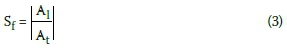
In the case of a symmetrical approach channel, the symmetricity factor (Sf) would therefore be equal to 0.5, and values less than 0.5 would indicate that an asymmetrical approach channel is perceptible. The classification of the symmetricity factor needs further investigation and will be published in a forthcoming paper.
CONCLUSIONS AND RECOMMENDATIONS
The change in the symmetricity of the approach channel has unambiguously proved to alter the shape of the ogee profile. This alteration is appreciated in the following ways:
■ The profile of the nappe differs along the length of the weir. From the experiments conducted it was also revealed that the side of the weir with the inclined sidewall caused the profile of the nappe to be higher than at the opposite side.
■ When comparing the asymmetrical approach channel's ogee profile with the baseline/symmetrical nappe profile, the profile of the asymmetrical approach channel configuration was increased at the vicinity of the inclined wall.
■ If an ogee spillway were to be designed considering only the two-dimensional flow parameters, problems would arise if the cross-section is asymmetrical. The profile would tend to be higher than expected towards the inclined sidewall of the structure, yet lower than expected on the opposite side. This may cause the dual problem of potential separation from the spillway structure causing cavitation damage due to sub-atmospheric pressure, and sub-optimal discharge on the opposite side, respectively.
The deduction of the comparison of measured profiles with the theoretically calculated ogee profiles produced diverse results:
i. The USBR (1987), USACE (1970), Hager (1987) and Ministry of Science and Technology (CE-05016) (2007) ogee approximations corresponded well with the geometry of the measured ogee profiles, although these curves had a tendency to underestimate the actual ogee profile at the position on the crest where the effective resistance to flow is a minimum.
ii. The downstream approximation made by Hager (1987) of the ogee curve appeared to overestimate the projection of the nappe profile in the downstream region of the ogee. This demonstrated that the formula was conservative and that the probability of sub-atmospheric pressure occurring in this region is minimised.
It is recommended that further studies be carried out (by making use of physical modelling) to assess the effect of the angle of the approach channel relative to the ogee spillway, as well as the curvature of the crest on the geometric shape of the ogee profile.
Results obtained from this study, as well as the studies proposed above, should be compared with a numerical simulation using a CFD analysis. It is absolutely imperative and critical to include the effect of three-dimensional flow when designing an ogee spillway. This is also indicative of the necessity of physical modelling during the design process, as theoretical curves do not necessarily provide optimal and safe solutions. A design guideline should be developed that would assist design engineers to design suitable, efficient and safe ogee spillways by considering parameters such as the asym-metricity of the approach channel.
ACKNOWLEDGEMENTS
We would like to thank the Water Research Commission for their valued contribution to this study, as well as the Department of Water and Sanitation for the use of their hydraulic laboratory.
REFERENCES
ASTM International 2001. Standard Test Method for Open-channel Flow Measurement of Water with Thin-plate Weirs. US Patent No. Designation: D 5242 - 92. [ Links ]
Chanson, H 2004. The Hydraulics of Open Channel Flow: An Introduction, 2nd ed. Oxford: Butterworth-Heinemann. [ Links ]
Chow, V T 1959. Open-channel Hydraulics, reprint. Illinois, US: The Blackburn Press. [ Links ]
Hager, W H 1987. Continuous crest profile for standard spillway. Journal of Hydraulic Engineering, 113(11): 1453-1457. [ Links ]
ISO (International Organization for Standardization) 2008. Hydrometry - Open-channel flow measurment using thin-plate weirs. Switzerland, Patent No. ISO 1438. [ Links ]
Knapp, R, Daily, W & Hammitt, F 1970. Cavitation. New York: McGraw-Hill. [ Links ]
Melsheimer, E S & Murphy, T E 1970. Hydraulic Design Criteria, Sheets 111-16 to 11-16/2. U.S. Army Corps of Engineers. [ Links ]
Ministry of Science and Technology (Myanmar) 2007. CE-05016. Design of Hydraulic Structures, Myanmar: Department of Technical and Vocational Education. [ Links ]
Momber, A W 2000. Short-time cavitation erosion of concrete. Wear, 241: 47-52. [ Links ]
Murphy, T E 1973. Spillway Crest Design. Vicksburg, MS: U.S. Army Corps of Engineers Waterways Experiment Station. [ Links ]
Rajaratnam, N, Subramanya, K & Muralidhar, D 1968. Flow profiles over sharp-crested weirs. Journal of the Hydraulics Division, ASCE, 94(HY3): 843-847. [ Links ]
Savage, B & Johnson, M 2001. Flow over Ogee Spillway: Physical and numerical model case study. Journal of Hydraulic Engineering, 127(8): 640-649. [ Links ]
Thandaveswara, B 2006. National Programme on Technology Enhanced Learning (NPTEL). Adras, India: Indian Institute of Technology. [ Links ]
USACE (U.S. Army Corps of Engineers) 1970. Hydraulic Design Criteria. Vicksburg, MI: USACE Waterways Experiment Station. [ Links ]
USACE (U.S. Army Corps of Engineers) 1987a. Hydraulic Design Criteria: Overflow Spillway Crest. Vicksburg, MI: USACE Waterways Experiment Station. [ Links ]
USACE (U.S. Army Corps of Engineers) 1987b. Hydraulic Design Criteria: Elliptical Crest Spillway Co-ordinates, Vicksburg, MI: USACE Waterways Experiment Station. [ Links ]
USACE (U.S. Army Corps of Engineers) 2009. Dam Safety Risk Analysis Best Practices Training Manual. Version 2.2 - April 2011 ed. Denver, CO: U.S. Department of Interior Bureau of Reclamation. [ Links ]
USBR (U.S. Department of Interior Bureau of Reclamation) 1987. Spillways, Chapter 9. In: Design of Small Dams, 3rd ed. Washington: U.S. Government Printing Office, pp 339-434. [ Links ]
Van Vuuren, S, Steyn, G, Pilz, N & Koch, H 2011. Influence of 3D approaching flow on a Curved Ogee Spillway Section - Neckartal Dam Namibia. Stellenbosch: UP Printers. [ Links ]
Vischer, D & Hager, W (Eds.) 1999. Dam Hydraulics. New York: Wiley, pp. 40-44. [ Links ]
Wahl, T L, Frizell, K H & Cohen, E A 2008. Computing the trajectory of free jets. Journal of Hydraulic Engineering, ASCE, 10.1061(2): 256-260. [ Links ]
 Correspondence:
Prof Fanie Van Vuuren
Department of Civil Engineering
University of Pretoria
Pretoria, 0001
South Africa
T: +27 (0)12 420 2438
E: fanie.vanvuuren@up.ac.za
Louis Coetzee
Department of Civil Engineering University of Pretoria
Pretoria, 0001
South Africa
T: +27 (0)12 481 3975
E: glouis.coetzee@up.ac.za
Dr Paul Roberts
SANCOLD
PO Box 3404
Pretoria, 0001
South Africa
T: +27 (0)12 460 9100
E: paul.roberts@worldonline.co.za

PROF FANIE VAN VUUREN Pr Eng is a professor in the Department of Civil Engineering at the University of Pretoria, and a project leader for a number of Water Research Commission projects. He has 39 years of experience in water resources engineering and holds BSc Eng, BSc Hons Eng, MEng, PhD (Eng) and MBA degrees, all from the University of Pretoria. He has worked as a specialist consultant for various consulting engineering companies, has written numerous technical reports, journal publications anc chapters in books, and has presented lectures in many countries.

LOUIS COETZEE obtained his BEng (Civil), BEng (Hons) and MEng (cum laude) in Water Resources Engineering at the University of Pretoria, and is currently studying towards a PhD. He joined the academic setting of the University of Pretoria as a junior lecturer in 2011 after completing his undergraduate studies. He obtained his early orofessional experience working for Sinotech CC and is currently employed as an Engineer at SMEC South Africa (Pty) Ltd. He has presented various courses on flood determination, flood lines, drainage structures, stormwater modelling, pipelines, pump stations and drainage systems in conjunction with Prof SJ van Vuuren. He has a specia interest in numerical and physical modelling of hydraulic structures and water distribution networks.

DR PAUL ROBERTS Pr Eng, a civil engineer, retired at the end of March 2003 from the then South African Department of Water Affairs and Forestry after a career of some 42 years in water resources management. Since retirement he has been active in consulting work in South Africa and Africa. He has also served as the SANCOLD South African National Committee on Large Dams) secretary since 2008.

