


Services on Demand
Article
 English (pdf)
 Article in xml format
 Article references
Indicators

Related links
-
 Cited by Google
 -
 Similars in Google
Share

 Permalink
Journal of the South African Institution of Civil Engineering
On-line version ISSN 2309-8775
Print version ISSN 1021-2019
J. S. Afr. Inst. Civ. Eng. vol.56 n.3 Midrand Oct. 2014
TECHNICAL PAPER
Parametric study on the behaviour of Y-shaped composite bridges
P Lu; C Shao
ABSTRACT
A composite Y-shaped bridge was analysed as a three-dimensional structure, using commercially available software. A finite element model to simulate the structural behaviour of the bridge was used to study its static and dynamic behaviour in order to gain a better understanding of the interaction between the main bridge and the ramp. An extensive parametric study was conducted, in which a typical composite Y-shaped bridge model was analysed and tested. The key parameters considered in this study were: loading conditions, ramp radius of curvature, ramp longitudinal slopes, bifurcate diaphragm plate stiffness, and loading cases. The structural behaviour of composite bridges is discussed in detail. The results from this study could enable bridge engineers to design complex composite Y-shaped bridges more reliably and economically.
Keywords: composite bridge, box girder, ramp, interaction, finite element method, experimental modal analysis
INTRODUCTION
Composite Y-shaped bridges have become an important component of highway systems, especially in urban grade separation bridges where multilevel interchange structures are necessary. As the curvature of highways increase due to space limitations, such bridges become more suitable. A typical bridge consists of a main bridge composite with a ramp or multi-ramps. The cross-section form of a composite bridge structure mainly adopts the box girder structure, which is favoured for its considerable torsional stiffness to resist applied loads. With the increase in the construction of such bridges, the analysis of the bridge structure is becoming more complicated, especially with regard to strained torsion, distortion angle, distortion warp and the shear lag effect. Various scholars have studied the design and structural analysis methods of the composite bridge structure (Sennah et al 2004; Samaan 2004; Cheung & Megnounit 1991; Hambly 1982; Morreu et al 1996; Mitra et al 2004; Vo & Lee 2007).
The typical composite structure is one of the most important parts of urban grade separation bridge structure. As shown in Figure 1, the typical composite bridge structure includes the main bridge, the curved ramp girder and crotches of irregular composite (Y-shaped bridge). Due to the interaction between the main bridge and the ramp, the mechanical behaviour of the composite structure is very complex and difficult to analyse in practical design. Kim and Kim (2003) analysed the thin-walled curved box beam under in-plane flexure. Analytical studies on cross-sectional deformations of curved box girders have been reported by several researchers. These studies are based on the thin-walled beam theory, the folded-plate theory, the finite-strip method and the block-finite-element method. Huang (2008) presented a procedure for obtaining the dynamic response and basic impact characteristics of thin-walled curved box girder bridges under truck loading. Dong & Sause (2010) presented a finite element method for considering material in-elasticity, second-order effects, initial geometric imperfections, and residual stresses of curved tubular flange girders. More recently, Okeil and El-Tawil (2004) reported on the effects of warping stress levels in 18 curved box girder bridges (adapted from the Florida Department of Transportation inventory) and pointed out that additional work was needed to define relevant parameters which could be used to identify bridges where warping calculations are warranted. In addition there are several theoretical and experimental studies on single curved girders (Thevendran et al 2000; Shanmugam et al 1995; Zureick et al 2000; Sennah & Kennedy 2001).
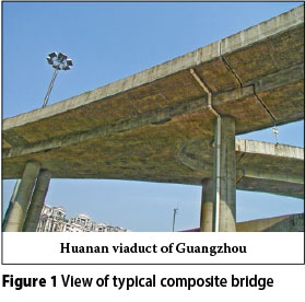
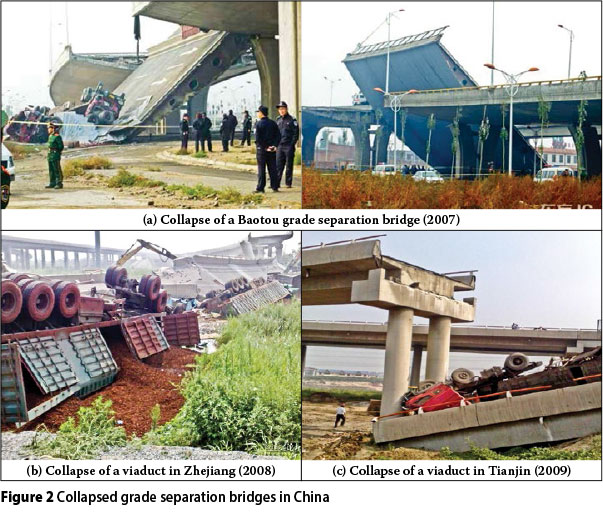
The main bridge member connects the curved girder of the ramp with crotches of irregular composite. The irregular crotches are used to resist interaction between the main bridge and the ramp members. This typical composite bridge structure was largely used in urban grade separation bridges in China. In recent years, with the increasing use of composite Y-shaped bridges, a number of Chinese urban grade separation bridges have collapsed, including grade separation bridges in Baotou (2007), Zhejiang (2008) and Tianjin (2009) (Figure 2).
In order to enhance the understanding of this area, and to calibrate the analytical model developed by the authors, full-scale testing and computer simulations were carried out on a curved concrete box girder bridge as suggested by Senthilvasan et al (2002). Heins and Sahin (1979) conducted static and dynamic tests on a steel two-span curved continuous box girder bridge in Seoul, South Korea, in order to calibrate several analytical procedures. Very few investigations have been conducted on composite Y-shaped bridges. A parametric study on the impact factors for 180 curved continuous multiple-box girder bridges was conducted by Samaan et al (2007). Lu et al (2007) presented the thin-walled beam theory, combined with finite element techniques, to provide a new thin-walled box beam element in the Y-shaped bridge. In an attempt to reduce collapse of this type of bridge structure, this paper investigates the behaviour of a typical Y-shaped composite bridge through experimental and analytical studies. The interaction between the main bridge and the ramp, and the dynamic performance of this combination, should always be considered in the design of a composite bridge. The design of Y-shaped bridges usually adopts thin-walled box girder sections, which affect both the constrained torsion and distortion of the structure. However, the mutual connection and restriction characteristics of the two bifurcate parts of the bridge structure under static and dynamic load cause constrained torsion and distortion, which could result in bridge failure. It is therefore necessary to study the mechanical behaviour of the Y-shaped bridge so that the study results can contribute towards the modelling of this interaction, and can be incorporated into bridge design.
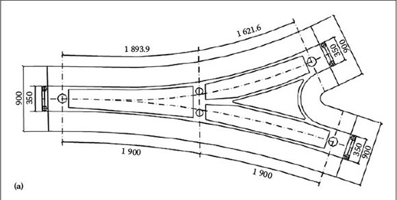
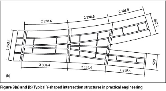
The mechanical behaviour of the Y-shaped bridge structure is complicated, particularly with regard to strained torsion and distortion, angle distortion, warp and shearing lag effect. The three different methods of analysing bridge structures in the past were mainly as follows: Firstly, the Y-shaped bridge structure was generally divided into two structures, which were then analysed independently. However, this method does not take the interaction between main bridges and ramps into account. Secondly, the analysis of the Y-shaped bridge structure was carried out according to the elementary beam theory, but this method does not take the restrained torsion, the distortion angle, the distortion warp, and the shearing lag effect into consideration. Thirdly, the analysis of Y-shaped bridge structure adopted the shell theory, but the direct internal forces cannot be obtained with this method, and the post-process workload is heavy. The above-mentioned methods therefore cannot ref lect the structural mechanical behaviour of the bridge, and may in fact contribute to the lack of safety of the structural design. To counter the problems mentioned above, and in order to enhance user safety of the Y-shaped bridge, two design methods are normally used in actual practical engineering, as illustrated in Figures 3(a) and (b).
The aim of this study is to conduct a parametric study in three dimensions to examine the effect of key parameters and loading conditions on composite Y-shaped bridges that might influence the impact factors of such bridges. The data generated from the study is used to deduce empirical expressions for impact factors relating to basic mechanical bridge behaviour.
EXPERIMENTAL SPECIMEN AND FINITE ELEMENT MODEL
Description of bridge prototypes and test modelling
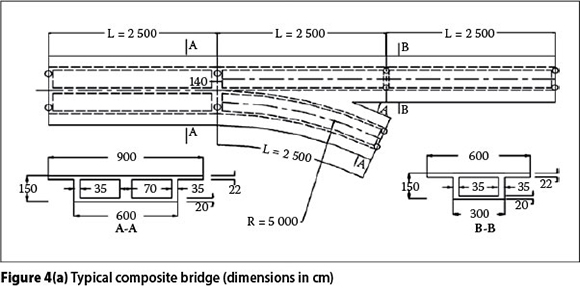
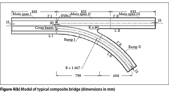
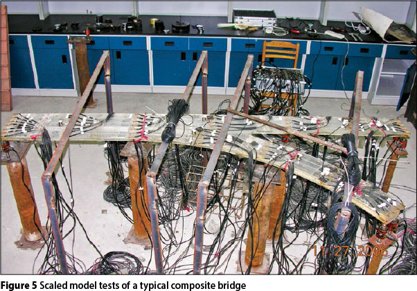
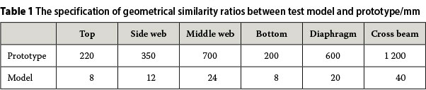
In this study, a typical composite Y-shaped bridge, from existing common urban grade separation bridges, was analysed (see Figure 4(a)), and then reduced in scale to an organic glass model as the test model (scale 1/30), as illustrated in Figure 4(b). All the members in the specimen were made of organic glass. The material properties of these glass members were determined by tensile coupon tests, as prescribed by the relevant standards, and the elasticity modulus Esand Poisson's ratio v of the composite bridge are 2.77 x 10³ MPa and 0.367 respectively. As the similarity ratio of stress between the prototype and the model is 5:1, the stresses that result from the model test will be the stresses for the prototype. The specification of a geometrical scale of 1/30 (see Figure 5) between the test model and the prototype in the specimen is given in Table 1. The ranges of the parameters considered in this study were based on an extensive survey of existing composite Y-shaped bridges.
Finite element modelling
The three-dimensional finite element model used in this study was verified by experimental results. The bridge models were instrumented to measure deflections, strains and support reactions. The experimental test results for longitudinal strains, deflections and support reactions were compared to the theoretical values derived from the same finite element model used herein.
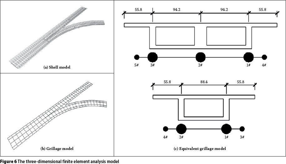
To extend the interpretation of the results and observations obtained in the test, and to gain a better understanding of the behaviour of a composite bridge, a parametric study on the composite Y-shaped bridge specimen was carried out using a finite element analysis (FEA) program. The three-dimensional FEA model is shown in Figure 6. Figure 6(a) was modelled with shell elements, Figure 6(b) was modelled with beam elements, and for Figure 6(c) the grillage analysis method was chosen to simulate the bridge.
The analysed Y-shaped bridge, with three-span main and two-span ramp, is a typical Y-bridge structure loaded at middle span on the upper surface of the concrete. The loaded area is 10 x 10 mm. The study uses the FE program to simulate the mechanical behaviour of the composite bridge, and establish a three-dimensional FE model (space grillage model and shell model) to analyse the behaviour of the Y-shaped bridge. In the shell model (commercial software), the four-node shell elements (shell63) were employed to model the concrete slab. The shell63 has both bending and membrane capabilities. The element has six degrees of freedom at each node, and the element is defined by four nodes. According to the bridge structure size and unit grid control precision, there are 397 shell elements in the shell model. In addition, in the space grillage model (numerical program considering the effect of torsion and distortion for new beam element) space grillages were modelled by two-node three-dimensional beam elements (considering the effect of torsion and distortion for a new beam element). In the space grillage model, the two-node primary new beam elements were employed to model the box beam. The new beam element has eight degrees of freedom at each node, and the element is defined by two nodes. According to the bridge structure size and unit grid control precision, there are 422 new beam elements in the grillage model. To study the effect of boundary conditions on the performance of the structure, three kinds of different boundary conditions are used in the model test and the analysis of the Y-shaped bridge respectively, as follows: (1) the fixed double support was set only in the bifurcation of the Y-shaped bridge, while the other places were set up as vertical single loading; (2) the fixed double support was set both in the bifurcation of the Y-shape bridge and at the end of the beam, while other places were set up as vertical single loading; (3) on the basis of two kinds of constraint conditions, the vertical single loading between the two curved ramps was set to vertical eccentric loading.
In this study the corresponding method of grillage analysis for the bridge at different boundary conditions was used by equivalent stiffness. The equivalent stiffness of the grillage analysis model was presented from the grillage analytical method obtained by equivalent stiffness principles. The change in different grillage stiffness for the bridge during the analysis was taken into account. The finite element model did not include the influence of cracks in the organic glass model. In this study the numerical simulations (shell model and grillage model) were carried out based on the above FE model, and numerical analysis results were calibrated against the corresponding experimental data. The shell element model cannot determine internal forces directly, and the post-process work load is heavy. The analytical method of grillage by essentially increasing the degree of freedom is an effective method to predict properties of this class of bridge. To simulate the experiments, the same loading conditions and constraints as used in the experiments were used in the finite element analysis.
PARAMETRIC STUDY OF STATIC BEHAVIOUR
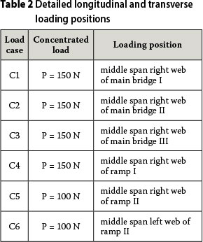
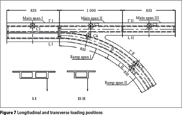
The testing equipment of the Bridge Engineering Department of Guangzhou University's research centre was used to test the model bridge under six different load cases. The axle loading corresponding to the number of steel blocks loaded are presented in Table 2. In order to detect bending behaviour, six static loading positions were determined to be the most unfavourable (stress-inducing) loading positions corresponding to each related span and girder. The detailed longitudinal and transverse loading positions are shown in Figure 7. Measurements of strain in the control section were conducted by means of electric resistance gauges at sections I-I, II-II and III-III. Deflections and transverse deformations were measured by means of deformation gauges at the control section. In the static and dynamic model test, the instruments and equipment used included a static data acquisition instrument (TDS-303 with a range of ± 16 000 με), a vibration testing system (DASP with a range of 0~20 kHz), and Analysis software.
Each control section carried six loading cases for the static bending test. Initial readings of all gauges were recorded with no loads on the model bridge. The loads were then applied and positioned at the predefined critical load positions on the model bridge. Strain and deflection readings were recorded for each loading case. After each loading case, the steel blocks were removed from the model bridge and another zero load reading was taken. The measured data was immediately displayed and compared with the analytical results to reveal any anomalies.
Influence of loading conditions on girder stresses
Bridge-loading conditions are normally considered to be major criteria affecting the girder stress of bridges, especially in Y-shaped composite bridges. Results obtained from the model composite bridge are shown in Tables 3 - 6. It was observed that girder stresses appear to change considerably with different loading conditions. For loading I conditions, the values of the girder stresses were generally greater than for loading II and loading III, especially in the ramp curve control section, and the analysis shows that loading II is close to loading III. Results furthermore showed the use of the powerful cross beam in the bifurcation of the Y-bridge. While the fixed double bearings support the bifurcation transverse beam, the powerful cross beam is used to reduce the interaction effect between the main bridge and the ramp. The fixed double bearing enhances the torsional performance of the cross beam, which reduces the huge positive moment and distortional warping bi-moment. When under outside load, the curved ramp of the composite bridge will lead to inside unloading, that is, increased outside deflection with gradually decreasing inside deflection. By comparing the different loading results calculated from the finite element analytical program, it is shown that eccentric loading produces reasonable internal forces, while the torsional double-loading of the end-diaphragm sections in a Y-shaped composite bridge is suitable to resist the torsional and warping effects induced by grade separation curvatures.
Influence of ramp radius of curvature on girder torsion and distortion
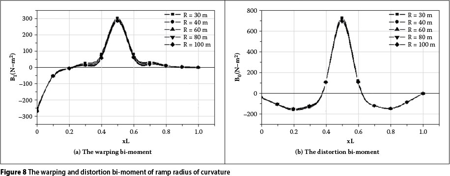
In the space grillage model (and while considering the effects of torsion and distortion), a new beam element was introduced, increasing the degrees of freedom from six per node to eight. Based on the three-dimensional space grillage FEA model of the new beam element, and Saint-Venant's principle, the relationships between the model composite bridge torsion, distortion and ramp radius of curvature are presented in Figure 8. The graph shows that the ramp radius of curvature has no significant effect on the torsion and distortion effect. However, it is observed that stress intensification factors of the middle-span section appear to increase considerably with decreasing ramp radius.
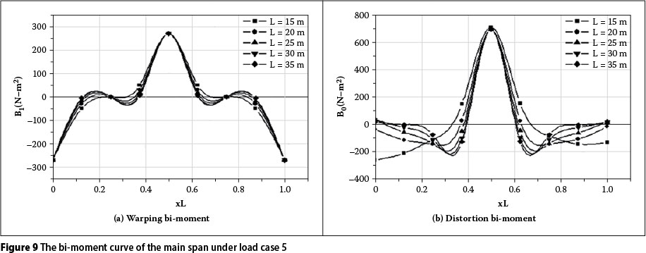
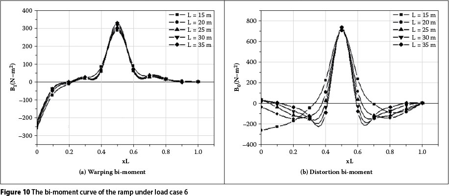
Influence of ramp span length on girder torsion and distortion
Five different lengths of 15, 20, 25, 30 and 35 m for each span subjected to loading cases 5 and 6 were considered in the parametric study. Based on the three-dimensional FEA model, the distribution of the warping and distortion bi-moments for the main bridge and ramp are presented in Figures 9 and 10. The graphs show that the maximum bi-moment of both torsion warping and distortion warping for the middle-span section remained almost unchanged; that is to say, the ramp span length has no significant effect on the torsion warping and distortion warping effect.
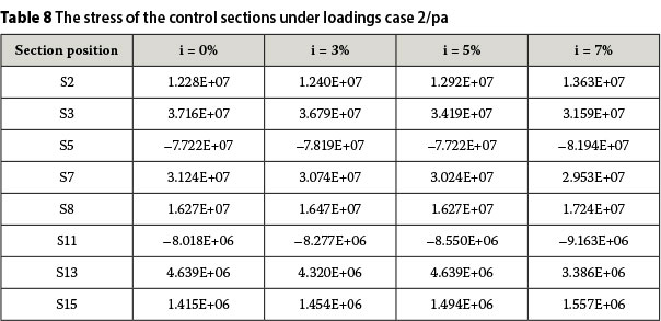
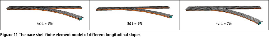
Influence of ramp longitudinal slope on girder stresses
A longitudinal transitional slope is essential between the Y-shaped composite bridge deck and the ground traffic. Longitudinal ramp bridge slopes of 3%, 5% and 7% were studied. Tables 7 and 8 show the effect of longitudinal slopes on girder stresses. Figure 11 shows the deformed shapes of different ramp longitudinal slopes for a Y-shaped bridge. It is obvious that the stresses of the control middle section increase with increase in the longitudinal slope, while the stresses of the loading section decrease with increase in the longitudinal slope. For example, the stress in the S7 section decreased by 5.46% when the longitudinal slope increased from 0% to 7%. Similarly, the stress in the middle section increased by almost 14.28%. These results therefore show that changing the longitudinal slope considerably affects the internal force of Y-shaped composite bridges.
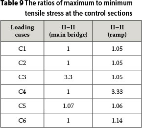
Influence of loading types on stress
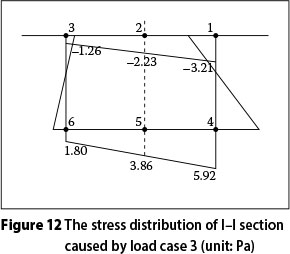
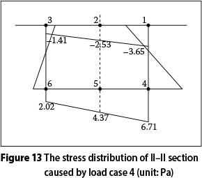
A comprehensive experimental study of the stress behaviour of control sections under six types of loading was performed, involving all the double fixed bearings, and the results were used to estimate the in-homogeneous distribution of the control section stress. Table 9 shows the effect of the tensile stress from maximum to minimum, which indicates that warping and distortion of the control sections subjected to eccentric concentrated force are greatly heightened, and stress distribution in the control sections is obviously non-homogeneous. Distribution of the part-normal stress is shown in Figures 12 and 13. The non-homogeneous distribution of stress at the control sections subjected to the eccentric uniform force is obvious, as is the decreasing stress. The warping and distortion of both the main bridge and the ramp are almost negligible. It should be pointed out that eccentric load should be taken into account in the warping and distortion control of Y-shaped bridges.
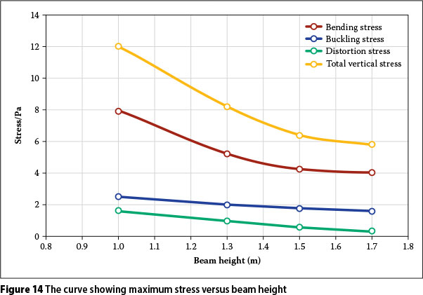
Influence of section height on girder stresses
Girder heights ranging from 1.0 m to 1.7 m were subjected to loading case 4 to determine the distribution of maximum tensile stress. Distortion stiffness, bending stiffness, warping stiffness and torsion stiffness for the structure subjected to the eccentric concentrated force increased correspondingly with an increase in the girder height. The stresses in the control sections decreased markedly with increase in the girder height, especially bending stress. The analysis showed that, for girder heights of 1.7 m to 1.0 m, the corresponding stresses in control sections may reduce by 54%, including mainly bending stress and warping stress, while distortion stress did not change significantly. Figure 14 shows the maximum stress versus beam height curve.
Influence of diaphragm width and stiffness on girder stresses
It is widely known that laboratory tests require a great amount of time, are very expensive and, in some cases, can even be impractical, while, on the other hand, the finite element method has in recent years become a powerful and useful tool for the analysis of a wide range of engineering problems. A comprehensive finite element model permits a considerable reduction in the number of experiments. Nevertheless, in a complete investigation of any structural system, the experimental phase is still essential. Taking into account that numerical models should be based on reliable test results, experimental and numerical/theoretical analyses complement one another in the investigation of a particular structural phenomenon.
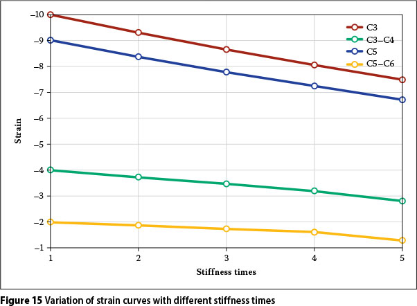
The diaphragms are located at the Y-shaped connection of the main bridge and ramp. Using a finite element model to reflect the effect of three different diaphragm stiffnesses on the mechanical behaviour of the bridge structure, three diaphragm widths of 0.5 m, 1.0 m and 1.5 m were modelled respectively. The analysis showed that, when the diaphragm width was increased to 0.5 mm, high moment capacity and rotation capacity were achieved. The stresses of the structure under loading case 4 decreased correspondingly with increase in the diaphragm width, and the stresses in sections I-I and II-II for diaphragm widths from 1.5 m to 0.5 m corresponding stresses at control sections may be reduced by 19.5% and 3.2% respectively. The modelling results show that the diaphragm width has an important influence on the stress in the control section of the main bridge and ramp. In addition, four diaphragm stiffnesses were modelled respectively two to five times. The results are shown in Figure 15.
From Figure 15 it can be seen that, when the diaphragm stiffness was increased two to five times, the strain of the control sections decreased by about 7%, 13%, 20% and 29% respectively. A stiffened bifurcation diaphragm would provide better stiffness for the connection between the main bridge and the ramp. Mechanical bifurcation diaphragm stiffening may be considered to prevent premature distortion, torsion or warping failure, and retain high stiffness and overall stability.
PARAMETRIC STUDY OF DYNAMIC BEHAVIOUR
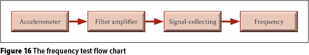
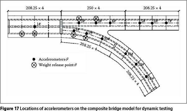
A DASP test system, with a vibration signal collecting system, charge filter amplifier and accelerometer, was used for the dynamic testing (Figure 16). Thirteen points were selected to measure the dynamic behaviour of the model bridge. Accelerometers 1 to 7 were instrumented at main bridge sections, while accelerometers 8 to 13 were instrumented at ramp sections. Figure 17 shows the locations of the accelerometers on the composite bridge model. At the same time, to comprehensively reflect the dynamic characteristics of the Y-shaped bridge structure in numerical analysis, the space shell finite element model was adopted to determine boundary conditions, radius of curvature and diaphragm, etc.
Influence of loading on mode shapes and frequencies
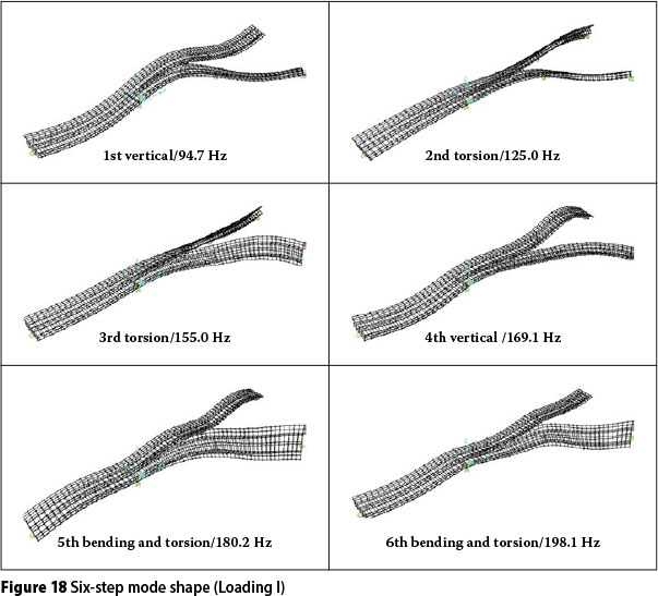
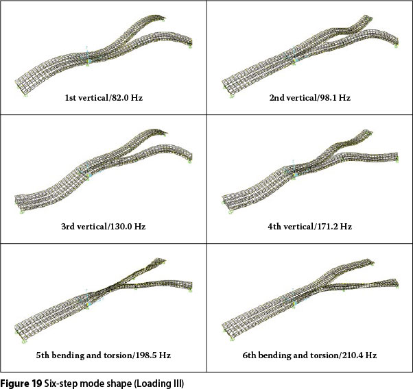
Bridge loading is normally considered a major criterion affecting the fundamental frequencies of bridges, especially in the Y-shaped composite bridge. Results obtained from the model composite bridges are shown in Figures 18 and 19. It can be seen that fundamental frequencies change considerably under different loading conditions. It is interesting to note that, for each loading condition, the values of the fundamental frequencies vary within torsional frequencies. Mode shapes were also derived for all the bridges studied. For the model composite bridges, the first mode shape was always purely flexural. Comparisons revealed that, with different loading conditions, the first mode shape for the model composite bridges varied in torsion mode, while the second mode shape became more predominant.
Influence of ramp radius of curvature on mode shapes and frequencies
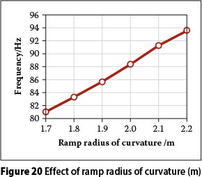
The relationships between the fundamental frequency and ramp radius of curvature are presented in Figure 20. The graph shows that increasing the ramp radius of curvature significantly increases the fundamental frequency. For instance, the fundamental frequency of mode bridges with a ramp radius of curvature of 1 667 mm increased by about 15.4% when the ramp radius of curvature increased from 1 800 mm to 2 200 mm.
Influence of bifurcate diaphragm plate stiffness
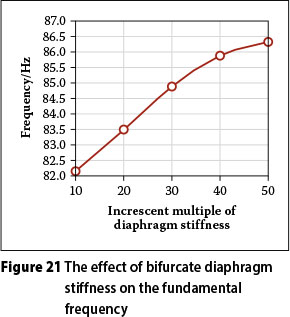
The effect of bifurcate diaphragm stiffness on the natural frequencies was examined. The results, shown in Figure 15, showed that bifurcate diaphragm stiffness has an effect on the modes. Providing bifurcate diaphragms at the bridge supports enhances the torsional stiffness significantly, and accordingly increases the natural frequencies. When the bifurcate diaphragm stiffness was increased to 10 mm, significant improvement in the torsional modes was shown. For instance, the fundamental frequency of mode bridges with bifurcate diaphragm plates of original stiffness increased by about 6.5% when the bifurcate diaphragm stiffness increased from ten to fifty times. The relationships between the fundamental frequency and bifurcate diaphragm stiffness are presented in Figure 21. Bifurcate diaphragm stiffness can therefore be used to improve the torsional frequency modes of Y-shaped composite bridges.
CONCLUSIONS
Parametric studies were conducted to evaluate the mechanical behaviour due to static and dynamic loading in which boundary condition, diaphragm stiffness, longitudinal slope, loading types, span length and ramp curvature, etc, were varied. The major conclusions from the investigation are as follows:
1. Based on a finite element program and existing commercial software (SAP2000), by comparing the results of the analyses of different boundary conditions, it is shown that the design method for eccentric loading in a Y-shaped bridge ramp is reasonable regarding the stress of the bridge structure. The torsional double-loading of the Y-shaped composite bridge is suitable to resist torsional and warping effects.
2. The ramp radius of curvature has no significant effect on torsion and distortion. However, it was observed that stress intensification on the middle-span section considerably increases with decreasing ramp radius.
3. In the middle-span section, the maximum bi-moments of torsion warping and distortion warping remained virtually unchanged; that is, the ramp-span length does not have a significant effect on torsion warping and distortion warping.
4. The results also show that changes to the longitudinal slope considerably affect the internal forces of Y-shaped composite bridges.
5. Warping and distortion are almost negligible when subjected to concentrated load. It must be pointed out that eccentric load
should be taken into account in the warping and distortion of Y-shaped bridges.
6. The reductive stresses of the control sections of the Y-shaped bridge included mainly bending stress and warping stress when the girder height reached a certain value, but the distortion stress did not change significantly.
7. Sufficient stiffness of the bifurcation diaphragm is necessary to prevent premature distortion, torsion or warping failure and overall instability. The main bridge and ramp are both connected into a whole by the bifurcation diaphragm. Sufficient stiffness of the bifurcation diaphragm, together with torsional double-loading and pre-eccentric loading of the ramp, effectively controlled the effects of the torsion and distortion of the main bridge and ramp. 8. Comparisons revealed that, with different loading conditions, the first mode shape for the model composite bridges varied in torsion mode, while the second mode shape became more predominant.
9. Increasing the ramp radius of curvature significantly increases the fundamental frequency. For instance, the fundamental frequency of mode bridges with a ramp radius of curvature of 1 667 mm increased by about 15.4% when the ramp radius of curvature increased from 1 800 mm to 2 200 mm.
10. Bifurcate diaphragm stiffness is adequate to improve the torsional frequency modes for Y-shaped composite bridges.
ACKNOWLEDGEMENTS
The writers gratefully acknowledge the financial support provided by the Science Foundation of China Postdoctoral Grants (No 20110490183), the Science Foundation of the Ministry of Housing and Urban-Rural Development of the People's Republic of China (Grant No 2012-K2-6), the Education Department Science Foundation of Zhejiang Province (Grant No Y201122051), the Science Technology Department of Zhejiang Province (Grant No 2012C21103) and the Science Foundation of Shanghai Postdoctoral Grants (No 13R21421100).
REFERENCES
Cheung, M S & Megnounit, A 1991. Parametric study of design variation on the vibration modes of box girder bridges. Canadian Journal of Civil Engineering, 18(5): 789-798. [ Links ]
Dong, J & Sause, R 2010. Behavior of hollow tubular-flange girder systems. Journal of Structural Engineering, 136(2): 175-181. [ Links ]
Hambly, E C 1982. Bridge superstructural capability. Beijing: China Communication Press. [ Links ]
Heins, C P & Sahin, M A 1979. Natural frequency of curved box girders. ASCE Journal of Structural Engineering, 105: 2591-600. [ Links ]
Huang, D 2008. Dynamic loading of curved steel box girder bridges due to moving vehicles. Structural Engineering International, 18(4): 365-372. [ Links ]
Kim, Y & Kim, Y Y 2003. Analysis of thin-walled curved box beam under in-plane flexure. International Journal of Solids and Structures, 40: 6111-6123. [ Links ]
Lu, P, Zhao, R, Zhang, J & Xing, T 2007. Y-shape bridge analysis based on space grillage method. Proceedings, 1st International Conference on Transportation Engineering, Southwest Jiaotong University Chengdu, China, pp 1292-1297. [ Links ]
Mitra, M. Gopalakrishnan, S & Seetharama Bhat, M 2004. A new super convergent thin walled composite beam element for analysis of box beam structures. International Journal of Solids and Structures, 41: 1491-1518. [ Links ]
Morreu, P J B, Riddington, J R, Ali, F A & Hamid, H A 1996. Influence of joint detail on the flexural/ torsional interaction of thin-walled structures. Thin- Walled Structures, 24: 97-111. [ Links ]
Okeil, A M & El-Tawil, S 2004. Warping stresses in curved box girder bridges: Case study. Journal of Bridge Engineering, 9(5): 487-496. [ Links ]
Samaan, M 2004. Dynamic and static analyses of continuous curved multiple box girder bridges. PhD thesis, Windsor, Canada: University of Windsor. [ Links ]
Samaan, M, Kennedy, J B & Sennah, K 2007. Impact factors for curved continuous composite multiple-box girder bridges. Journal of Bridge Engineering, 12(1): 80-88. [ Links ]
Sennah, K M & Kennedy, J B 2001. State-of-the-art in design of curved box-girder bridges. Journal of Bridge Engineering, 6(3): 159-167. [ Links ]
Sennah, K M, Zhang, X & Kennedy, J B 2004. Impact factors for horizontally curved composite box girder bridges. Journal of Bridge Engineering, 9(6): 512-520. [ Links ]
Senthilvasan, J, Thambiratnam, D P & Brameld, G H 2002. Dynamic response of a curved bridge under moving truck load. Engineering Structures, 24(10): 1283-1293. [ Links ]
Shanmugam, N E, Thevendran, V, Richard Liew, J Y & Tan, L O 1995. Experimental study on steel beams curved in plan. Journal of Structural Engineering, 121(2): 249-259. [ Links ]
Thevendran, V, Shanmugam, N E, Chen, S & Richard Liew, J Y 2000. Experimental study on steel-concrete composite beams curved in plan. Engineering Structures, 22: 877-889. [ Links ]
Vo, T P & Lee, J 2007. Flexural-torsional behavior of thin-walled closed-section composite box beams. Engineering Structures, 29: 1774-1782. [ Links ]
Zureick, A, Linzell, D, Leon, R T & Burrell, J 2000. Curved steel I-girder bridges: Experimental and analytical studies. Engineering Structures, 22: 180-190. [ Links ]
 Correspondence:
Pengzhen Lu
Faculty of Civil Engineering and Architecture Zhejiang
University of Technology
Hangzhou310014
PR China
T: +86 0571 88320153
E: pengzhenlu@zjut.edu.cn
Changyu Shao
Shanghai Municipal Engineering Design and Research Institute
Shanghai 200092
PR China
T:+8602151298
E: Smedi@Smedi.com

DR PENGZHEN LU is Associate Professor in the Department of Civil Engineering at Zhejiang University of Technology in Hangzhou, China. He received his PhD from Southwest Jiaotong University in 2010. He has a broad interest in structural analysis and design, encompassing numerical modelling and experimental work. His major current interest is the modelling, with finite elements, of the linear and nonlinear behaviour of composite bridges. A parallel development/interest is composite structural application, including the composite beam and pre-stressed composite beam, especially the calculation theory and analytical method for composite box beams. He is also interested in uniquely shaped bridges, bridge evaluation and bridge strengthening, particularly as there are many old bridges in China that need structural attention.

DR CHANGYU SHAO is a China Bridge Survey and Design Master and Professor, and chief engineer at the Shanghai Municipal Engineering Design and Research Institute. He obtained a BSc in Civil Engineering from Tongji University in 1984, and a PhD in Civil Engineering from the same university in 2007. He has a broad interest In composite structural behaviour and design work.

