


Services on Demand
Article
 English (pdf)
 Article in xml format
 Article references
Indicators

Related links
-
 Cited by Google
 -
 Similars in Google
Share

 Permalink
Journal of the South African Institution of Civil Engineering
On-line version ISSN 2309-8775
Print version ISSN 1021-2019
J. S. Afr. Inst. Civ. Eng. vol.56 n.3 Midrand Oct. 2014
Effects of safety factors on the deflections in a concrete gravity dam
M Opan
ABSTRACT
The aim of this study was to determine the effects of safety factors on the deflections of a concrete gravity dam. Overturning and sliding safety factors for a selected concrete gravity dam with base width b and height H were specified, using pseudo analysis for the b/H ratios and earthquake acceleration values between 0.1 g and 0.4 g. Deflection values for specified parameters were obtained from the structural analysis program SAP2000. Deflection safety factor curves, determined from the b/H ratios, were obtained, as well as the earthquake acceleration values. The results of this analysis showed that safety factors reduced while strain values increased.
Keywords: concrete gravity dam, pseudo analysis, deflections, safety factors
INTRODUCTION
Rapid developments in computer technology over the last few decades have made it possible to apply advanced structural analysis techniques to predict the behaviour, and therefore the safety, of concrete dams during earthquakes. However, many uncertainties remain in predicting the behaviour of dams during severe earthquakes. Amongst these are crack formation and propagation in the concrete body of the dam, nonlinear behaviour of the foundations, and the interaction of the water body in the reservoir with the dam structure (Ghrib et al 1997; Chopra 1998; Kreuzer 2000). Static and dynamic approaches, and linear or nonlinear finite element models have been combined with statistical methods in studies of stability analysis to evaluate the safety of dams (Hall 1998; Tinawi et al 2000; Leclerc et al 2003). A further issue is determining the most appropriate definition for seismic input, as this has a very significant effect on the seismic design and seismic safety evaluation of dams. Many uncertainties still exist in this regard, but progress has been made in defining the maximum credible earthquake (MCE), maximum design earthquake (MDE) and safety evaluation earthquake (SEE). With more seismic records available now, the effects of the very short duration peak ground acceleration (PGA) (which may be from 0.5 g to 1.0 g, or even higher in severe earthquakes), and the sustained effective seismic acceleration (which could be about 0.5 - 0.67 of PGA), are now better understood. An indirect result of seismic activity is the effect of increased seepage on uplift forces, due to increasing pressure acting through cracks in the concrete body or under the foundations. This must be taken into account in the stability analysis for seismic design, as it may have a very significant effect on the safety of the dam. Opan and Temiz (2007) reported that safety factors decrease with earthquake acceleration and pressure reduction.
The aim of this study was to determine the relationship between the deflections and safety factors at topping, and at toe, for a concrete gravity dam (CGD) during an earthquake. A CGD with base width b and height H was specified, using pseudo analysis for the b/H ratio and earthquake acceleration values between 0.1 g and 0.4 g. Deflection values for specified parameters were obtained from the structural analysis program SAP2000. Graphs were plotted for the selected dam from the results of the b/H ratio and earthquake acceleration, and the deflection and safety factors were evaluated.
FORCES ON A CONCRETE GRAVITY DAM DURING AN EARTHQUAKE
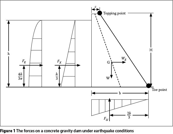
The forces on a CGD under earthquake conditions are the horizontal hydrostatic load, the horizontal hydrodynamic load, the vertical pore water pressure force, the weight of the CGD and the earthquake force due to the CGD weight. These forces are shown in Figure 1, where FEis the horizontal hydrody-namic load, Fxis the horizontal hydrostatic load, Fuis the vertical pore water pressure load, W is the weight of the concrete dam, WEis the concrete dam weight and earthquake load on the horizontal direction, and b, c, h and H are the parameters of the concrete dam.
The horizontal hydrostatic load is:

The horizontal hydrodynamic load is:

where a is the reduction factor (a is between 0.543 and 0.555) for the earthquake force (Westergaard 1933).
Vertical pore water pressure force is:

The weight of the concrete dam wall is simplified by assuming that the cross-section of the wall is a triangle with base b and height h. In other words H = h. The weight of the concrete gravity dam is:

Earthquake force due to concrete gravity dam weight is:

where ywand γ are the specific weights of concrete and water respectively and m is the pressure reduction factor for the water pressure force (0 < m < 1). The ratio α is the earthquake acceleration divided by gravitational acceleration.
PSEUDO ANALYSIS
Pseudo analysis for dams is based on dam stability. The stability of a CGD is provided by its moments. If the moment that attempts to tip the dam at the toe point is lower than the resisting moment, the dam remains stable. This is demonstrated in Equation 6:

With the substitution of Equations 1 to 5, this is equivalent to:

After simplification, it becomes:
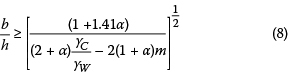
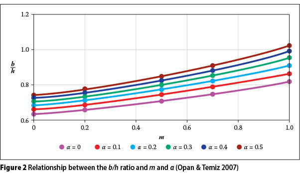
Equation 8 provides a relationship between the b/h ratio, and m and α are obtained. This relationship is shown in Figure 2 where  is2.5.
The overturning safety factor is attained from the ratio of resist moment to subvert moment. According to this definition, the overturning safety factor is obtained below:

After substitution and rearrangement, it becomes:
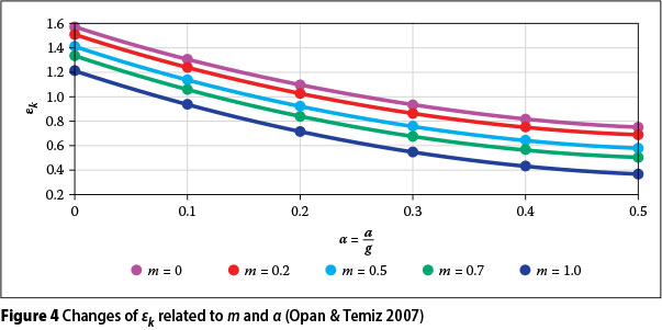
where  is accepted as 2.5. The ratio b/h is found versus m and α, changes of sdconnected with m and α are obtained, and sd decreases with increasing values of m and α The sliding safety factor is attained from a ratio of resist force to sliding force. According to this definition, the sliding safety factor is obtained as follows:

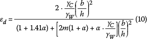
With the rearrangement of this equation, Equation 12 is formed:

where  are accepted, and b/h is obtained versus m and α in Equation 8.
Changes of εd and εk related to m and α are calculated as shown in Figures 3 and 4, where it can be seen that εd and εk decrease with increasing values of m and α.
STRUCTURAL ANALYSIS USING SAP2000
A CGD is modelled by using the shells of the finite element in the SAP2000 program. The principal axis of the dam in this program is shown in Figure 5. Shells are separated into 0.50 χ 0.50 meshes, as shown in Figure 6. Small dimensions are chosen for these meshes to achieve results closer to reality. Deflection values for topping and points are attained by establishing models in different mesh dimensions. Mesh dimension is defined by considering computing time and the fact that there are no changes in deflection. The foundation soil of the dam was modelled via the spring element. The density of the soil was accepted as being sand-loose and sand-medium, and the modulus of sub-grade reaction was chosen as ks= 2 500 t/m3. The stiffness of the spring element was determined by using the modulus of the sub-grade reaction and foundation effective area. Analyses were performed at h = 10 m, H = 10 m, m = 0.2, 0.6 and1.0, and at b/h ratios 0.6, 0.8 and 1.0. Note that the analysis was simplified by assuming a wall height H to be the same as the water depth h. Deflection values at every direction are read from the topping point and toe point, as shown in Figure 1. Deflection vectors of these points are obtained as follows:


where δ is the deflection vector.
RESULTS
The effects of safety factors on the deflections in a concrete gravity dam during an earthquake were determined in this study. A concrete gravity dam with a base width b and height H was specified, using pseudo analysis for the b/H ratios and earthquake acceleration values between 0.1 g and 0.4 g. Values for specified parameters were obtained from the structural analysis program SAP2000. Graphs were plotted for the selected dam from the results of the b/H ratio and earthquake acceleration, and the deflection and safety factors were evaluated.  were accepted in the pseudo analysis.
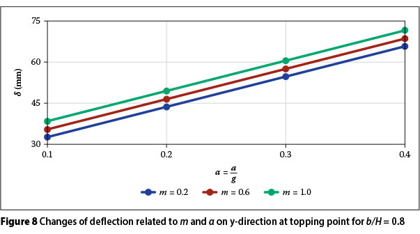
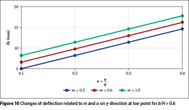
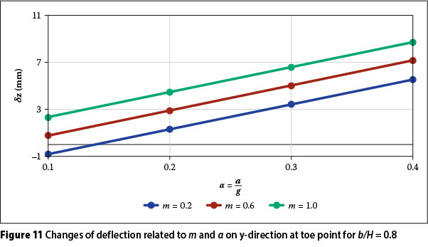
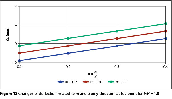
In Figure 2 it can be seen that the b/h ratio increased with an increase in m and α. In Figures 3 and 4 the safety factors decreased with increasing m and α. Deflection of the topping point related to m and α at b/H = 0.6, 0.8 and 1.0 are shown in Figures 7, 8 and 9 respectively. It can therefore be said that deflection increased with increasing m and α. Deflection of the toe point related to m and α at b/H = 0.6, 0.8 and 1.0 are shown in Figures 10, 11 and 12 respectively. Deflections increased with increasing in and, and deflections decreased with an increase in the b/H ratio.
CONCLUSIONS
In this study, tipping and sliding safety factors of a dam during an earthquake, and deflections at toe and topping points, were determined. Pseudo analysis was performed to define safety factors. Changes to these safety factors versus m and α were investigated, and it was seen that safety factors decreased with increasing m and α. SAP2000 was used to determine deflections at the toe and topping points. According to the changes in these deflections versus m and α it can be said that deflection increased with increasing m and α. In addition, safety factors increased with increasing b/H, while deflection decreased with increasing b/H. Further research should cover analysis and studies regarding crack formation and dispersion in a concrete gravity dam during an earthquake.
REFERENCES
Chopra, A K 1998. Earthquake response analysis of concrete dams. In Jansen, R B (Ed). Advanced dam engineering for design, construction and rehabilitation. New York: Van Nostrand Reinhold, pp 416-465. [ Links ]
Ghrib, F, Le'ger, P, Tinawi, R, Lupien, R & Veilleux, M 1997. Seismic safety evaluation of gravity dams. International Journal on Hydropower and Dams, 4(2): 126-138. [ Links ]
Hall, J F 1998. The dynamic and earthquake behavior of concrete dams: Review of experimental behavior and observational evidence. Soil Dynamics and Earthquake Engineering, 7(2): 58-117. [ Links ]
Kreuzer, H 2000. The use of risk analysis to support dam safety decisions and management. Proceedings, ICOLD 20th Congress, Beijing, China, Gr. Q. 76, pp 769-834. [ Links ]
Leclerc, M, Le'ger, P & Tinawi, R 2003. Computer aided stability analysis of gravity dams. Advances in Engineering Software, 34: 403-420. [ Links ]
Opan, M & Temiz, T 2007. Safety factors for the seismic design of concrete gravity dams. Paper presented at the International Earthquake Symposium Kocaeli 2007, Turkey, 22-26 October. [ Links ]
Tinawi, R, Le'ger, P, Leclerc, M & Cipolla, G 2000. Seismic safety of gravity dams from shake table experiments to numerical analysis. ASCE Journal of Structural Engineering, 126(4): 518-529. [ Links ]
Westergaard, H M 1933. Water pressure on dams during earthquakes. ASCE Transactions, 98: 418-472. [ Links ]
 Correspondence:
Mücahít Opan
Department of Civil Engineering Kocaeli
University Umuttepe Campus Kocaeli Turkey
T: +90 262 303 32 72
F: +9 0 2 62 3 03 3 0 03
E: opanmucahit@yahoo.com

PROF DR MÜCAHÍT OPAN, who was born in Sivas, Turkey, is currently Associate Professor in the Department of Civil Engineering at Kocaeli University in Kocaeli, Turkey. He obtained his basic degree in civil engineering from the Selçuk University in Konya, Turkey, in the mid-nineties, his Master's from Yildiz Technical University in Istanbul, Turkey, in the late-nineties, and his PhD from Kocaeli University in 2007.

