


Services on Demand
Article
 English (pdf)
 Article in xml format
 Article references
Indicators

Related links
-
 Cited by Google
 -
 Similars in Google
Share

 Permalink
Journal of the South African Institution of Civil Engineering
On-line version ISSN 2309-8775
Print version ISSN 1021-2019
J. S. Afr. Inst. Civ. Eng. vol.55 n.3 Midrand Jan. 2013
TECHNICAL PAPER
Structurally efficient housing incorporating natural forms
M Gohnert; A Fitchett; I Bulovic; N Bhlkhoc
ABSTRACT
Structural optimisation has been the subject of intense research for many years. However, the engineering profession seems to be oblivious to the important role of natural structures. Natural structures are shapes created by nature and possess geometrical properties that are resistant to environmental conditions. Engineers of antiquity recognised the importance of natural shapes and incorporated these designs into many political and religious structures. Many of these structures are catenary or funicular in form, and are characterised by a pure compressive stress distribution - an essential requirement for masonry structures. Catenary shapes are robust and economical. These principles are applied to the design and construction of a prototype shell - a domed vault - intended as an alternative structure for low-cost housing. Design principles are described, as well as the construction process.
Keywords: shells, vaults, catenary, earth bricks, low-cost housing, masonry
INTRODUCTION
The evolution of structures has progressed from trial-and-error to structures with a scientific, experimental and theoretical basis. Over time, the engineering profession has developed an understanding of structures, expressed in mathematical or physical forms. Our technical abilities have expanded exponentially with the development of new structural materials and shapes: concrete strengths have improved a hundred-fold and steel can now be considered a "designer material". A variety of steel products are available, depending on the whim and wishes of the client. New structural materials have also been introduced, such as high-strength plastics, hardened glass and carbon fibres, fashioned together to create a variety of attractive structural designs. Theoretical modelling, such as finite element analysis, is found in every design office, enabling complex calculations not previously envisioned to be made. CAD packages have evolved to such high sophistication that a tour of a building may now be taken in a virtual environment, without a single brick being laid.
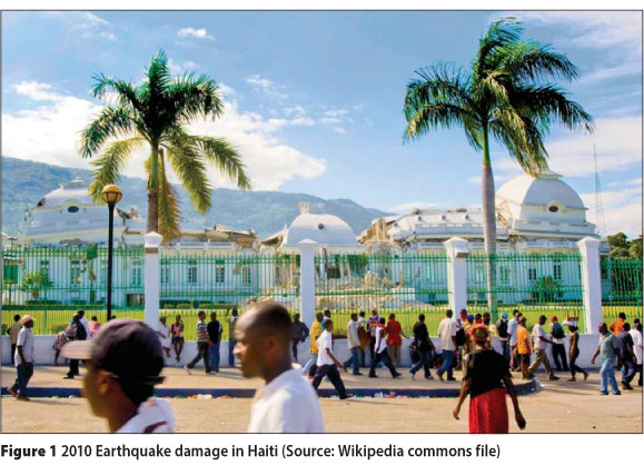
Is it possible that our rapid path of development has blinded us to reason and logic? Sometimes we fail to see the obvious, even when it stares us in the face. Figure 1 is a photo taken after the 2010 earthquake in Haiti. In the background, the Presidential Palace lies in ruin. In the foreground, scores of the homeless inhabit the street. As engineers, it is natural to focus on the collapsed structure and form a hypothesis as to the cause of failure. However, we fail to see the obvious - the manmade structure has failed, but the natural structures have survived - the palm trees are still standing, without any outward signs of distress. Perhaps we will never work and live in palm trees, but the shape and flexibility of this natural structure is perfectly resistant to earthquakes and significant meteorological occurrences - thus, a structure based on nature is a more appropriate form for the Haitian environment.
Natural structures have, perhaps, evolved over millions of years into optimum shapes that are resistant to local environmental conditions. Would it not be prudent to learn from these structures and emulate them in our designs (Bejan & Lorente 2006)?
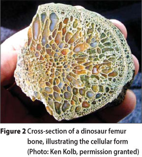
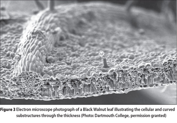
Nature possesses and persistently reproduces several universal features. All natural structures have curved surfaces and solid forms are not solid, but composed of cellular or tubular shell-like substructures. As an example, Figure 2 is a cross-section of a dinosaur femur bone and Figure 3 is the cross-section of a Black Walnut leaf. In these examples (fauna and flora) the structure and substructure of the natural forms are curve-shaped and composed of shells. The curvature of the shapes is directly related to the flow of stress, dictated by the imposition of environmental conditions. The curvature of the femur bone constitutes resistance to the actions of walking, running, jumping, etc. Leaves, which are miniature solar panels engaged in the act of photosynthesis, are designed to resist wind flutter, rain, snow and the invasion of insects. Each shape takes on a suitable form to optimise resistance to environmental forces and to ensure the species' ultimate survival.
STRUCTURAL EFFICIENCY OF RESISTING FORCES
An important concept in comprehending the strength of curved structures is to understand how loads are efficiently carried by structures. To illustrate this concept, a simple example is given in Figure 4.
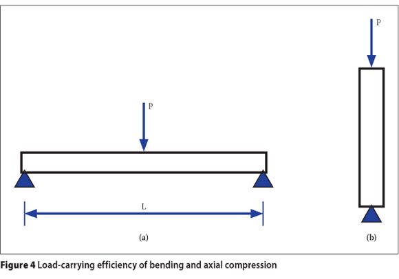
The maximum bending stress (σb) of a beam subjected to a point load (Figure 4a) is expressed by Equation 1.
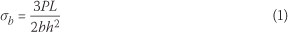
where
L = length
h = depth of the beam
b = width
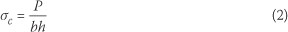
If the same load is resisted by an axial member, the maximum compressive stress (σc) (Figure 4b) in the column is given by Equation 2.
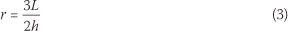
If the bending stress in the beam (σb) is divided by the column stress (σc), the ratio of the stresses (r) is given by Equation 3.
The value (L/h) is the span-to-depth ratio, which usually falls within prescribed values (SANS 10100-1 2000). Table 1 is a list of stress ratios for a variety of simple load and beam support conditions. The stress ratio represents the increase in stress compared with that of an axially loaded member. As indicated in the first row of Table 1, the stress in a simply supported beam subjected to a point load is 24 times higher than that in an axially loaded member. Similarly, the stress increase in other beam load/support configurations ranges from 12 to 18 times the stress in a column.
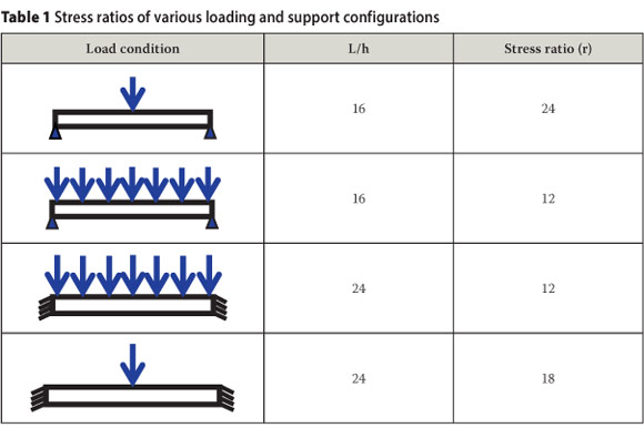
Resisting forces by bending is highly uneconomical compared with axial resistance. Avoiding bending, however, is not always feasible with our current practice of designing box-shaped linear structures. Table 1 demonstrates that greater efficiency is achieved by directing the flow of force along the axis of the member. The axis, however, does not necessarily have to be straight.
A stress will flow along the axis of a curved member or along the curvature of a shell if the shape is catenary. The catenary is a natural form in which stresses will flow in pure compression or tension. Unlimited variations of the catenary are also possible by varying the loads and corresponding shape.
FORGOTTEN LESSONS OF OUR FOREFATHERS
The discovery of natural structures and their importance seems to have occurred around the 17th century arising from the work of Robert Hooke (O'Dwyer 1999), the same person who developed the theory of elasticity (i.e. Hooke's Law). Hooke, a celebrated scientist, discovered the significance of a hanging chain and its relationship to structural forms. He recognised that a hanging chain is in complete tension, without bending and shears. If the chain is locked and inverted, the stress in the chain is reversed and in pure compression. The importance of this discovery is that loads may be carried in pure compression, eliminating shears and bending.
Strangely, Hooke's discovery was written in the margins of his scientific works - seemingly a fleeting thought. Translated from Latin,
"... as hangs the flexible line, so but inverted will stand the rigid arch."
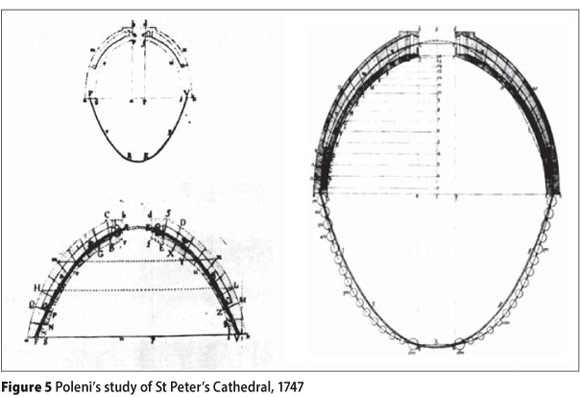
One of the first notable applications of Hooke's arch theory was applied to St Peter's Basilica in Rome. The dome exhibited serious cracking and the safety and stability of the structure was questioned. In 1743 Pope Benedict XIV appointed Giovani Poleni to assess the structure (Lopez 2005). Poleni hung 32 weights on a chain to represent the self-weight of the dome walls. The resulting profile of the chain represented the natural thrust line, which was inverted and superimposed on a scaled cross-section of the dome walls (see original drawings in Figure 5). Since the chain profile fitted within the walls of the dome, the structure was deemed stable and safe for occupation. According to Poleni, if the thrust line fell outside the walls, tension cracking would be expected and the structure would be unstable. He concluded that the source of cracking was the inferior materials used in construction, rather than a mismatch of the thrust line. Nearly three centuries later, St Peter's Basilica remains stable as predicted, substantiating Poleni's analysis.
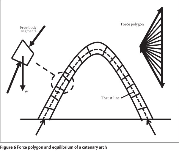
The application of the catenary shape to structural forms was taken further by Culmann and Stevin (Block 2006) who developed a graphical analysis method, referred to as the force polygon method (in later years, called the "tip-to-tail" method) (Firmage 1980). The graphical analysis method was the dominant method of structural analysis until the early 1900s. For this reason (until recently), graphical methods were taught in most engineering programmes. Figure 6 illustrates the force polygon of an arch. The weighted diagonal arrows of the force polygon represent the reactions at the base, and the weighted vertical arrow is the total vertical load of the arch. The lines fanning from the left-hand point of the polygon represent the internal thrusts of the free-body segments. The arch may be randomly discretised or the free-body segments may be actual masonry blocks. By satisfying the equilibrium of each segment of the arch, a catenary shape forms automatically.
The catenary shell is, perhaps, the most time enduring shape known to humankind. The Pantheon in Rome is nearly two millennia old, yet proudly remains intact and serviceable. Although the inner surface of the dome is a hemisphere, the secret of the Pantheon is its outer profile, which is catenary, thus permitting the flow of stress in pure compression (Goshima 2011). Although Hooke is credited with the discovery of the catenary, evidence suggests that knowledge of the catenary may have been known much earlier by the Romans, the master builders.
Historically, the catenary dome was used only in a few notable structures, advocated by antiquity's most prominent engineer-architects, who recognised and understood the structural importance of these shapes. By far the majority of shells were hemispheres. These shapes, however, frequently cracked due to hoop tensions at mid-height and bending and shears at the base (stress characteristics of a hemisphere). For this reason, hemispherical domes were often clad with sheets of copper or tiles to make the shells water-tight, cover unsightly cracks and improve durability.
Unfortunately, the practice of implementing natural forms seems to have faded in the early 1900s - an incomprehensible digression in structural design. Utilising natural forms should be a logical choice, especially in the design of low-cost housing for which structural and material efficiency is of paramount importance.
APPLICATION OF NATURAL SHAPES TO HOUSING STRUCTURES
The South African Department of Housing (Sexwale 2009) has reported a serious dearth in low-cost housing. The deficiency is approximately 2 million homes, exclusively among the low-income sector of society. The key issue is affordability, for the recipients, who are largely unemployed or underemployed. Alternative housing forms and new construction materials are therefore necessary, since existing building forms are unsatisfactory in quality and price. Shell structures, which are natural forms, are ideally suited as the shape provides both superior strength and economy of materials.
Although not covered in this paper, shells are climatically appealing and energy efficient, since their internal temperatures are known to be more evenly distributed - a welcome and important attribute for low-cost housing. This benefit, however, is only fully realised if the shell is insulated (Wilson 2005).
The shape investigated was the catenary vault, which may be described as two catenary barrel shells intersecting at right angles. A vault was chosen for practical reasons
- vertical walls are constructed on the four open sides of the shell, allowing for finishes and furniture that are more suited for box-shaped homes.
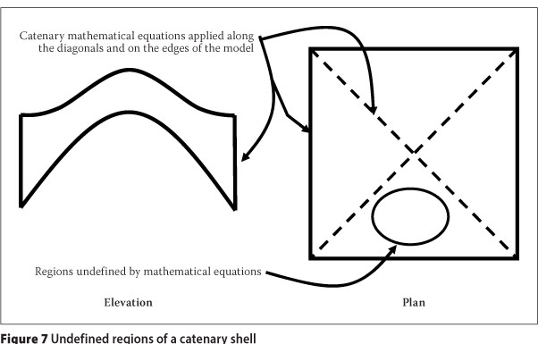
The shape of the vault is more complex than that of a catenary arch or dome. The catenary mathematical formula is two-dimensional and can only be inscribed on the shell diagonally, from support to support, and along the open edges of the shell (Figure 7); the shape is therefore undefined between the inscribed catenary curves. The mathematical expression of the catenary was developed by Gregory (1706), in response to a competition.
where the symbol a is a constant, defining the amplitude and width of the curve.
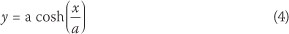
The force polygon method is also only suited to two-dimensional shapes or shapes that have rotational symmetry about a vertical axis (e.g. cupola or conical shapes). For these reasons, physical working models are implemented to define the surface of the shell using a hanging model, as illustrated in Figure 8. The model was constructed of plaster of Paris medical bandages, hung to a specified width:height ratio. The model was then photographed and the coordinates, defining the shape of the shell, were measured. The resulting shape was then scaled to match the size of the full-scale version. Fabric models must be relatively flat to prevent, or minimise, the restraining effects of the weave from defining the shape of the model incorrectly.
The concept of the hanging model is similar to the hanging chain, but in three dimensions. When the hanging model is inverted, the stresses are transformed into pure compression, which is ideally suited to masonry structures. Most important, the hanging model is an appropriate method for defining the shape of the shell in the undefined regions (Figure 7).
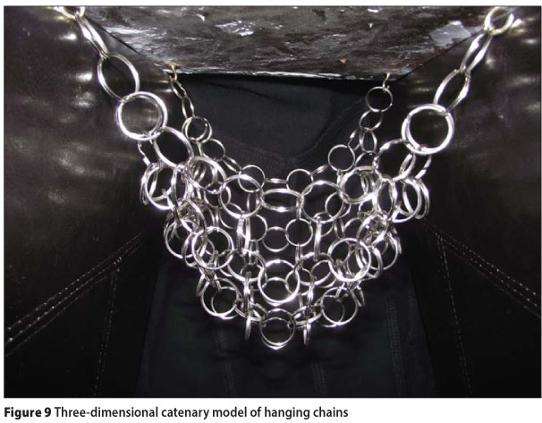
A three-dimensional chain model was also constructed (Figure 9) to emulate the modelling methods of antiquity. However, this method was found to be more difficult to work with. It was almost impossible to define the coordinates from photographs and therefore this method was not used in the design. Designers of the past implemented hanging chain models to define the shape of structures. The coordinates were painstakingly determined by means of rulers and squares. As a consequence, the working models comprised very few draping chains and the shapes were simple (i.e. without openings). However, the simplicity of the dome models accumulated into highly complex representations if the design was composed of multiple shells. Antoni Gaudi's Sagrada Familia in Barcelona is an example of a structural design done by means of three-dimensional chain models (Figure 10) (Wikipwdia commons file).
CONSTRUCTION OF THE CATENARY VAULTED SHELL
The construction of the shell consisted of two parts: firstly, the construction of the formwork, using earth tiles to define the shape of the shell; and secondly, the construction of successive layers of tiles to achieve the desired thickness. The tiles are composed of compressed cement-stabilised earth, measuring 290 mm x 140 mm x 20 mm, and having a compressive strength of approximately 7 MPa. The plan dimensions of the vault measured 3 m x 3 m and had an apex height of 2 m. The prototype shell is approximately 1/2 scale.
Four small pad footings were constructed, which were tied by steel straps along the boundaries. The purpose of the pad footings is to resist the vertical loads, and the straps resist the horizontal outward thrusts of the shell. Both structural elements are absolutely vital to maintain stability and satisfy equilibrium requirements. In a full-scale structure, however, the foundation would be in the form of a strip foundation. A prominent and common feature of low-cost housing is damage caused by uneven settlement. Shell structures are typically lighter and therefore cause less soil stress. A unique feature of a similar dome, constructed in Johannesburg, is the orientation and configuration of the foundations (Talocchino 2005). The foundations were orientated vertically (turned 90°) to provide stiffness - if uneven settlement occurs, the structure is designed to settle without distorting the shell.
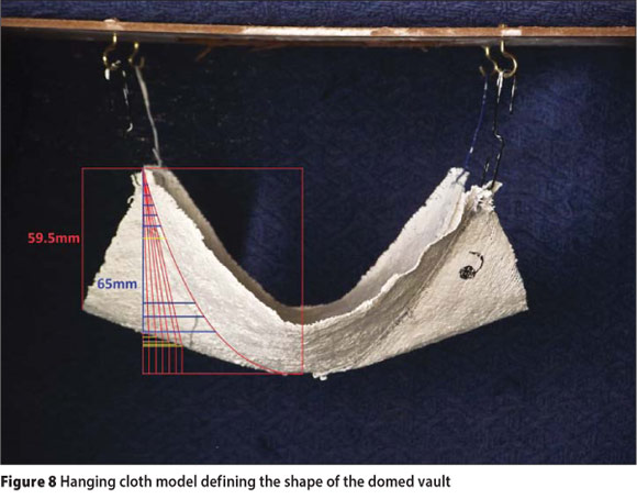
Four catenary-shaped guides were placed on top of each foundation, used to construct the four arches along the edges of the shell (see Figure 11). The first layer of tiles is "glued" together using Crystacal R, which is a high-strength, rapid-hardening plaster of Paris. The initial set usually occurs within 1 minute (depending on the temperature), allowing rapid construction of the initial layer of tiles.
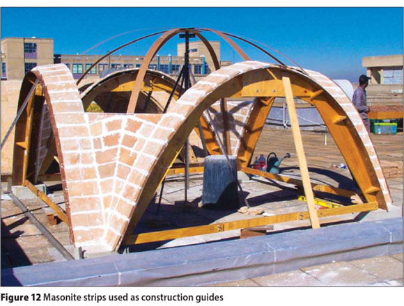
Formwork was kept to a minimum to economise on construction. In addition to the edge arches, four Masonite strips were placed diagonally, spanning between the pad footings (Figure 12). The Masonite strips were used as guides to construct the "domed" portion of the vault.
The first layer of tiles is the most important layer since it defines the shape of the shell. The thrust line must match the curvature of the shell and therefore the accuracy of the first layer is of paramount importance. Not only does the first layer define the shape, but it also acts as formwork for successive layers.
Additional layers are then applied to the top surface of the first layer and ordinary mortar is used in-between and along the edges of the tiles. The prototype model has two layers of tiles over the entire surface, but additional tiles are placed near the supports to account for the accumulation of compression forces at the base of the shell. The thickness of the shell is determined by comparing the estimated stress and theoretical capacities of the compressive and buckling strengths of the shell.
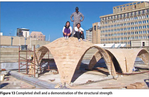
Figure 13 is a photo of the completed shell. The thickness of the shell is 50 mm (two layers of tiles, separated by 10 mm of mortar). The shell is completely unrein-forced and the resistance is based on the compressive strength of the tiles. The shell is ultra-thin, but capable of resisting the load of three individuals (see Figure 13), thus demonstrating the incredible strength of catenary shapes.
Since shell structures are optimal and materially efficient, higher accuracy in construction is required to ensure that the constructed shape is within tight tolerances. Supervision is an obvious necessity, but creative construction techniques can minimise construction error and allow the engagement of unskilled labour. For example, the hemispherical shell constructed in Johannesburg used inflatable formwork, in the shape of a balloon. The balloon provided a template and bricks were laid on the surface of the balloon by ordinary bricklayers. After the mortar had set, the balloon was deflated and reused in the construction of other shells. The technique permitted rapid erection of the formwork, a guiding template to ensure construction accuracy and reuse of the formwork.
Shells have declined in popularity, which may have been due to the difficult and time-consuming task of erecting formwork or guiding templates. Furthermore, the relatively low cost of materials and the high cost of labour advocates simplicity and speed of construction, which has taken preference over the optimisation of shapes. The world economies, however, have changed in recent years, causing an increase in the cost of materials and therefore concepts of sustainability must be incorporated into new designs - these factors may spur a revival in shell design.
CONCLUSIONS
Nature should be the engineer's mentor. The shapes and forms we see in nature have evolved over time and are optimally load-resistant structures. Many of these are catenary shapes, which are resistant to environmental conditions. Ironically, architects endeavour to replicate building forms that harmonise with the environment. The correctness of this approach is far more apparent when structural resistance and the economy of materials are considered.
Natural shapes have inspired and enlightened the engineering profession for centuries. Catenary concepts have been incorporated into numerous buildings, the majority of which are religious, with the intention of lasting for eternity (and many of these structures probably will!). They have participated in the test of time and have proved to possess superior strength and resilience. Why natural shapes have become foreign to our profession is an absolute mystery. We have deviated from the obvious and have forgotten the lessons of the past.
The dearth of housing in South Africa dominates our agenda and much of the country's resources have flowed in this direction. We need housing that is robust and economises on materials - natural forms fit these requirements perfectly. A scaled-down prototype was designed and constructed to determine the constructability and strength of a catenary vault. The catenary vault has demonstrated incredible strength, despite being constructed of ultra-thin layers of compressed earth tiles. No steel was incorporated, yet the shell does not exhibit any surface cracking. This implies that the shape is a natural form (i.e. the thrust line coincides with the centre line of the shell walls) and is therefore a highly efficient structure.
ACKNOWLEDGEMENT
The authors would like to acknowledge the generous contribution of Hydraform, who donated the earth bricks used in the construction of the catenary vault.
REFERENCES
Bejan, A & Lorente, S 2006. Constructal theory of generation of configuration in nature and engineering. Journal of Applied Physics, 100: 041301. [ Links ]
Block, P, DeJong, M & Ochsendorf, J 2006. As hangs the flexible line: Equilibrium of masonry arches. Nexus Networking Journal, 8(2): 9-19. [ Links ]
Firmage, D A 1980. Fundamental Theory of Structures, 2nd edn Huntington, New York: Robert E. Krieger Pub. Co. [ Links ]
Goshima, R, Ohmori, H, Hagiwara, N & Aoki, N 2011. Investigation of the cross-section of the Pantheon dome through catenary mechanisms. Journal of the International Association for Shell and Spatial Structures, 52(1): 19-23. [ Links ]
Gregory, D 1706. The properties of the catenaria. Miscellanea Curiosa, Vol. II, Royal Society of London, published by Harvard University Library, pp 219-250. [ Links ]
Lopez, G M 2005. Poleni's manuscripts about the Dome of Saint Peter's. Available at: http://www.arct.cam.ac.uk/personal-page/james/ichs/Vol%202%201957- 1980%20Lopez.pdf:957-1979. [ Links ]
O'Dwyer, D 1999. Funicular analysis of masonry vaults. Computers & Structures, 73: 187-197. [ Links ]
SANS 10100-1 2000. The Structural Use of Concrete, Part 1: Design. The South African Bureau of Standards, Pretoria. [ Links ]
Sexwale, T 2009. Housing Budget Vote Speech, 30 June 2009. Department of Housing Available at: http://www.housing.gov.za. [ Links ]
Talocchino, G 2005. Design and construction criteria for domes in low-cost housing. MEng dissertation, University of the Witwatersrand, Johannesburg. [ Links ]
Wilson, A 2005. A practical design of concrete shells. Monolithic Dome Institute, Italy, Texas, US. [ Links ]
 Contact details:
School of Civil and Environmental Engineering
University of the Witswatersrand
PO Wits, 2050, South Africa
T: +27 11 717 7125, F: +27 11 717 7045
E: mitchell.gohnert@wits.ac.za
Contact details:
School of Civil and Environmental Engineering
University of the Witswatersrand
PO Wits, 2050, South Africa
T: +27 11 717 7107, F: +27 11 717 7045
E: anne.fitchett@wits.ac.za
Contact details:
School of Civil and Environmental Engineering
University of the Witswatersrand
PO Wits, 2050, South Africa
T: +27 11 717 7142, F: +27 11 717 7045
E: vanjabulovic@gmail.com
Contact details:
PO Box 45008
Mayfair, Johannesburg
2108, South Africa
T: +27 11 646 3684
E: nafisabhikhoo@gmail.com

PROF MITCH GOHNERT graduated from Brigharr Young University, USA, with a BSc In CM Engineering and a Master's degree In Engineering Management in 1985 and 1987 respectively. In 1995 he was awarded a PhD in Civil Engineering from the University of the Witwatersrand. He is registered as a Professional Engineer in South Africa anc as a Chartered Engineer in the United Kingdom. He is a full professor in structural engineering and is currently the Head of the School of Civil and Environmental Engineering at the University of the Witwatersrand.

BR ANNE FITCHETT Is currently a Senior Lecturer n the School of Civil and Environmenta Engineering at the University of the Witwatersrand, teaching in the fields of project management and environmental engineering. Her primary research interest lies in abour-intensive construction methods, with a particular focus on thin-shel masonry structures. She was on the professional team for the Mapungubwe Interpretation Centre, Limpopo Province, which won the 2009 World Architectural Festival award as "Building of the Year". She has taught in the School of Architecture for 20 years, predominantly in the field of architecture history, and was consultant to the Rhodes Ratepayers Association to formulate the conservation policy for the village.

VANKABULOVIC graduated with a BSc In Clvl Engineering in 2011 and is currently doing her MSc at the University of the Witwatersrand. Her specialisation falls within the field of structura engineering, with a particular focus on thin shells.

MAFISA BHIKHOO graduated from the University of the Witwatersrand with a BSc in Civil Engineering in 2011. She then worked for the Marine and Coastal engineering consultancy Prestedge Retief Dresner Wijnberg. Nafisa's top Honours at university Included obtaining ar Academic Excellence Scholarship, admission into the Golden Key Society, making the Dean's List and achieving the Award for Top Honours Project in conjunction with Ivanka Bulovic to which she contributed the research discussed in this journal article. She intends pursuing a Master's degree in the field of Civil and Environmental Engineering.

