


Servicios Personalizados
Articulo
 Inglés (pdf)
 Articulo en XML
 Referencias del artículo
Indicadores

Links relacionados
-
 Citado por Google
 -
 Similares en Google
Compartir

 Permalink
Journal of the South African Institution of Civil Engineering
versión On-line ISSN 2309-8775
versión impresa ISSN 1021-2019
J. S. Afr. Inst. Civ. Eng. vol.55 no.3 Midrand ene. 2013
TECHNICAL PAPER
Critical normal traffic loading for flexure of skew bridges according to TMH7
A D Malan; G C van Rooyer
ABSTRACT
Different types of loading due to traffic may act on bridges. The focus of this paper is on normal traffic loading according to the South African specification TMH7 (Committee of State Road Authorities 1988). TMH7 represents the code of practice for the design of highway bridges and culverts in South Africa. The aim of the paper is to provide additional insight into the effect of normal traffic loading patterns on the flexural analysis of skew bridges. This is necessary since TMH7 does not explicitly specify application patterns for normal traffic loading. Only the intensity of normal traffic loading is specified and it should be applied to yield the most adverse effects. In this paper a set of so-called "standard application patterns" are investigated and compared with the application patterns that yield the most adverse effects. The patterns are compared for flexural effects in selected design regions of the bridge deck. Numerical experiments were performed and are presented for a typical single-span bridge deck. The results of the numerical experiments are compared as the angle of skew of the bridge deck increases.
Keywords: bridge traffic loading, skew bridges, TMH7, software development, finite element analysis
INTRODUCTION
This paper is concerned with flexure of skew bridges under the effects of normal traffic loading according to TMH7. Normal traffic represents a formula loading consisting of the most severe arrangement of legal vehicles that is probable (Committee of State Road Authorities 1988). The incorporation of heavy vehicles, requiring abnormal load permits, is excluded from normal traffic loading. The problem statement and particular aim of the investigation are formulated in the next section.
Problem statement and aim of investigation
Bridge structures are subject to dead loads and live loads. Dead loads refer to permanent loads, e.g. the own weight of the structure. Live loads, such as live loads due to traffic, refer to loads that may act at various possible locations on the bridge deck. Without the aid of specialised software or influence surfaces, the determination of the positions where traffic loads should be applied to produce the most adverse effects is not obvious. The problem is exacerbated by the following:
■ The most adverse effects are not necessarily obtained when the bridge deck is fully loaded.
■ The South African specification TMH7 does not explicitly specify application patterns for live loading due to traffic.
The problem arises as to how the traffic loads should be applied to produce the most adverse effects.
Influence surfaces and design charts
For complex structures with complex loading arrangements, influence surfaces and design charts are usually employed to determine the effect in a specific region resulting from the application of a load in another region. However, influence surfaces and design charts have the following disadvantages (Hambly 1976):
■ They are not always easy to use.
■ They do not give the user a complete picture of the force system in the bridge deck under the effect of a particular load case.
■ They cannot be used for orthotropic, cellular or beam-and-slab decks due to their different distortional and torsional characteristics.
Furthermore, published influence surfaces and design charts are not available for all types of structural geometries and support conditions in each of the regions of the bridge deck.
Load application patterns
Given the problems associated with the application of normal traffic loading described above, the aim of this paper is to answer the following questions:
■ Is it possible to use a set of standard application patterns to approximate the most adverse effects of normal traffic loading?
■ If standard patterns are used, by how much will their results differ from the most adverse results?
■ How well do the standard application patterns perform when the angle of skew of the bridge deck increases in plan view?
The set of standard application patterns mentioned above will be developed and presented after TMH7's specifications concerning normal traffic loading have been described. Thereafter, the generation of application patterns that produce the most adverse effects will be presented. Numerical experiments, in the form of qualitative, comparative finite element analyses, will be performed for a typical single-span bridge deck. The results of the standard application patterns will be compared with those of the most adverse application patterns as the angle of skew of the bridge deck increases in plan view.
NORMAL TRAFFIC LOADING
The geometries of the components of the bridge deck and normal (NA) traffic loading are presented here.
Bridge deck geometry
This investigation of critical normal traffic loading is restricted to the modelling and analysis of the bridge deck, i.e. the whole bridge structure is not considered. The carriageway, supports and notional lanes are defined as follows:
■ Carriageway: The carriageway includes all traffic lanes and represents that part of the bridge deck where traffic loads must be applied.
■ Supports: Supports are represented as line-type supports beneath the carriageway. Vertical displacement is restricted by the supports, i.e. the displacement perpendicular to the plane of the bridge deck.
■ Notional lane: Notional lanes represent longitudinal strips along the carriageway, used for the application of normal traffic loading.
The bridge deck geometry, as defined above, is presented in Figure 1 for a skew bridge deck in plan view.
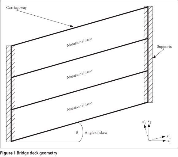
The notional lanes do not represent the actual traffic lanes. The width and number of notional lanes are specified by TMH7 and they are dependent only on the effective width of the carriageway.
Definition of NA loading
Type NA loading, as specified by TMH7 (1981, revised 1988), consists of a distributed part and a concentrated part acting in conjunction with each other. The distributed part can either be in the form of two equal and parallel line loads spaced 1.9 m apart, or in the form of a distributed load over the full width of the notional lane. The concentrated part of type NA loading can either be in the form of two equal point loads spaced 1.9 m apart, or in the form of a knife-edge load over the full width of the notional lane. The two possible application methods of type NA loading are illustrated in Figure 2.
The intensity of the distributed part of type NA loading is dependent on the effective loaded length of the part where it is applied. The concentrated axle part is dependent on the loading sequence of the relevant notional lane. The intensities of type NA loading are described further in the sections below.
Distributed load
The distributed part of type NA loading represents a nominal distributed lane load, acting on the whole or parts of the length of any notional lane or combination of such lanes. In the longitudinal direction the loading is uniformly distributed for any continuous part of a notional lane, but the intensity may be different for separate parts:
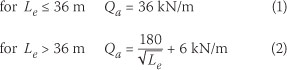
where
Le = effective loaded length (m)
Qa = intensity of the loading (kN/m).
The specification of TMH7 provides a procedure whereby the loading intensities are based on the assumption that the total loading is dependent on the aggregate loaded length of all the notional lanes being considered (see Section 2.A.2.1 of Part 2 of TMH7). The intensities of the loading in these separate parts are not necessarily equal. The loading procedure for the distributed part of type NA loading is presented according to method A(i) of TMH7 (Committee of State Road Authorities 1988):
That part of any notional lane, which has the maximum average influence value (positive or negative as the case may be), is loaded at an intensity determined by the NA uniformly distributed loading formula for that loaded length. Thereafter, that part of the same or any other notional lane with the next highest average influence value of similar sign is loaded at an intensity such that the total load on the two loaded parts corresponds to the formula loading for a loaded length equal to the sum of the two loaded lengths.
If  is the sum of all the loaded lengths up to and including the pth part, the intensity of loading Qap on the pth part of length Lp is defined as follows:
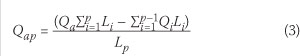
where
Qa = intensity of the loading for a length of 
Qi = intensity of loading applied to previously calculated base length potion i
Li = dimension of any previously calculated base length potion i.
In this procedure Qap reduces as p increases with no limiting value.
Concentrated load
The concentrated part of type NA loading is in the form of one nominal axle load per notional lane with the following intensity:
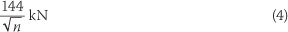
where
n = loading sequence number of the relevant notional lane.
For example, n = 1 for the first lane loaded with the axle load, n = 2 for the second loaded lane, etc. The concentrated axle part of type NA loading is applied in conjunction with the distributed part and only one axle load must be applied per notional lane.
LOADING PATTERNS
Based on the definition and intensity of type NA loading presented above, two approaches regarding the application of loading are developed, namely so-called "standard patterns" and "critical patterns".
Standard patterns
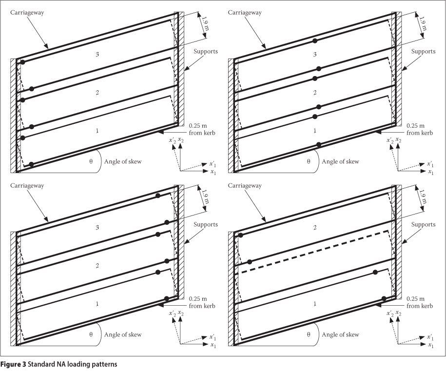
The standard patterns are based on intuition and engineering judgement, i.e. how an engineer could consider applying type NA loading to yield the most adverse effect if he/ she did not have access to influence surface-based software. The proposed standard patterns are illustrated in Figure 3.
In the case of the standard patterns as illustrated in Figure 3, the highest intensity loading is applied towards the bottom edge of the carriageway in the transverse direction. The concentrated axle part of type NA loading is applied towards the left, the centre and the right in the longitudinal direction respectively. A basic torsion load is also included. When the standard patterns are used, all the loadable parts of the notional lanes are loaded, with a decreasing intensity when the effective loaded length exceeds 36 m.
The standard NA loading patterns provide a systematic procedure for loading a carriageway. It is easy to implement a programmatic procedure to generate standard NA loading patterns for a carriageway with any number of spans and any number of notional lanes.
Critical patterns
The standard NA loading patterns, as described in the previous section, load all the loadable parts of the notional lanes of a specific span. As a result, certain regions that may provide a relieving effect will also be loaded, which results in less adverse values. To avoid this, a method is presented that generates critical positive or negative loading patterns for a selected mode of failure. The critical loading patterns are based on the influence value, at a chosen location, of a load increment as it moves over the notional lanes. A short, distributed line load segment-pair is moved over all the loadable parts of the notional lanes of the carriageway in steps, as shown in Figure 4.
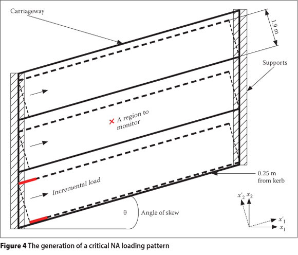
A critical pattern, as illustrated in Figure 4, is generated as follows:
■ A region in the carriageway, as well as a mode of failure, are selected for which the critical pattern should be generated.
■ The load increment segment-pair moves step-wise over all the loadable parts of the carriageway, as indicated by the arrows in Figure 4.
■ The influence of the moving load increment segment-pair on the selected mode of failure in the chosen design region is documented, specifically:
■ whether its current position causes a positive or negative effect in the selected design region, and
■ the magnitude of the current position's influence on the selected mode of failure.
The critical positive pattern for the selected region and mode of failure is produced when:
■ loads are applied only at locations that caused a positive effect, and
■ loads are applied following a decreasing sequence of their influence magnitudes.
In this way, the maximum-intensity distributed load is applied at the position where it causes the most adverse effect, while reduced-intensity distributed loads are applied where the adverse effect is less. Similarly, the concentrated axle loads will be placed at the position with the highest influence value in each of the notional lanes that should be loaded.
In order to produce the critical negative loading pattern for a specific region and mode of failure, the same procedure is followed, except that the loads are only applied at locations that caused a negative effect.
A critical NA loading pattern, for a selected mode of failure and a specific design region, will provide the following information:
■ Which of the loadable parts of the notional lanes should be loaded to provide the most adverse effect:
■ Which of these parts should be loaded first, i.e. with the highest intensity loading.
■ Which of the remaining parts should be loaded next with decreasing intensities, if applicable, and in what sequence.
■ Which loadable parts of the notional lanes should not be loaded:
■ The parts that should not be loaded would provide a relieving effect, i.e. a less adverse effect, if they are in fact loaded.
Critical NA loading patterns provide the most adverse positive or negative effect in a specific region for a selected mode of failure.
Comparative analyses
Qualitative finite element analyses were performed in which the results yielded by the standard patterns were compared with those of the critical patterns. For the purpose of qualitative analysis, the exact cross-section of the bridge deck does not have to be taken into consideration and the deck was modelled as an equivalent slab with constant thickness. The standard and critical patterns of type NA loading were applied to the carriageway and the values were compared relative to each other for various angles of skew of the bridge deck. The errors between the two sets of results were documented for angles of skew ranging from 0° to 40° in increments of 10°. They were measured for each of the moment resultants in the corresponding critical regions. The percentage error is defined as:

where
v0 represents the value produced by the critical pattern
v1 represents the value produced by the envelope of the standard patterns.
A value from the critical pattern was compared with the corresponding value from the envelope of the standard patterns, i.e. the critical value is compared with the nearest or "best" value from the set of standard patterns. The percentage error, as defined above, should always be negative or zero, otherwise the critical pattern would not be the most adverse pattern.
INTERPRETATION OF RESULTS
In order to interpret the results of the comparative analyses, the definition of moment resultants and the selection of critical design regions are now presented.
Definition of moment resultants
This paper is concerned only with the flex-ural behaviour of skew bridges. The concept of flexure corresponds to twisting and bending of the bridge deck under loads, which in turn translates into twisting and bending moment resultants. The moment resultants are defined below:
Bending moment vector: A bending moment vector is defined as Mij, where i indicates the direction of the moment vector and j indicates the face on which the vector acts.
The different moment resultants are illustrated in Figure 5.
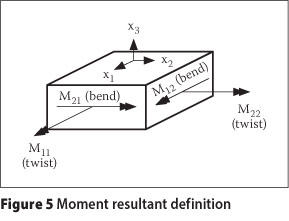
The bending moments are M12 and M21, and the two twisting moment vectors are M11 and M22. The latter two are of equal magnitude and opposite sign.
Selected design regions
For the purpose of this paper three design regions were chosen where each of the moment resultants would be measured and where they typically reach their critical values. The selected design regions and the corresponding moment resultants are marked with an "x" in Figure 6.
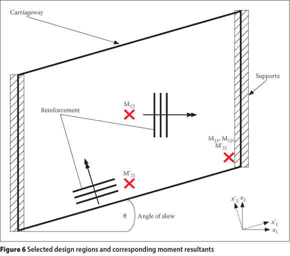
The selected design regions, the corresponding moment resultants and the assumed reinforcement layout are described below:
■ Mid-span edge: The longitudinal bending moment M'21 is measured in this region. As illustrated in Figure 6, the accented axes represent rotated axes which correspond to the angle of skew. Moment resultant M'21 represents the bending moment vector in the rotated x2-direction, acting on the rotated x1-face. It is assumed that its corresponding reinforcement will be placed in the rotated longitudinal direction, parallel to the edge of the carriageway.
■ Mid-span centre: The transverse bending moment M12 is measured in this region. Moment resultant M12 represents the bending moment vector in the x1-direction on the x2-face. The transverse bending moment has to be resisted by the reinforcement in the transverse direction, as shown in Figure 6.
■ Obtuse corner: The twisting moment M11 is measured in this region.
In general, the transverse and longitudinal bending moments also reach significant values in the obtuse corner. These results are not within the scope of this paper, i.e. only the twisting moment will be considered in the obtuse corner.
RESULTS
The results of the detailed comparative analyses are presented for a typical single-span, simply-supported carriageway. For critical and standard loading patterns the results are compared as the angle of skew of the carriageway increases from 0° to 40°. A carriageway with a span length of 15 m and an effective width of 10 m, e.g. a typical inner span of a multi-span bridge deck, was considered.
Twisting moment
The twisting moment in the bottom right obtuse corner of a skew carriageway (see Figure 6) is considered here. The corresponding critical NA loading patterns and resulting twisting moment contours are illustrated in Table 1.
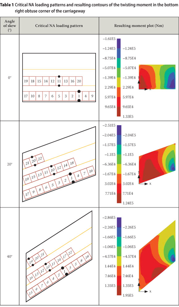
The following can be observed from Table 1 regarding the twisting moment in the obtuse corner:
■ To produce the critical NA loading pattern for the twisting moment in the bottom right obtuse corner, the top right acute corner of the carriageway should not be loaded.
■ It can be seen from the load indices that the highest intensity loading should be applied towards the bottom edge of the carriageway in the transverse direction and towards mid-span in the longitudinal direction.
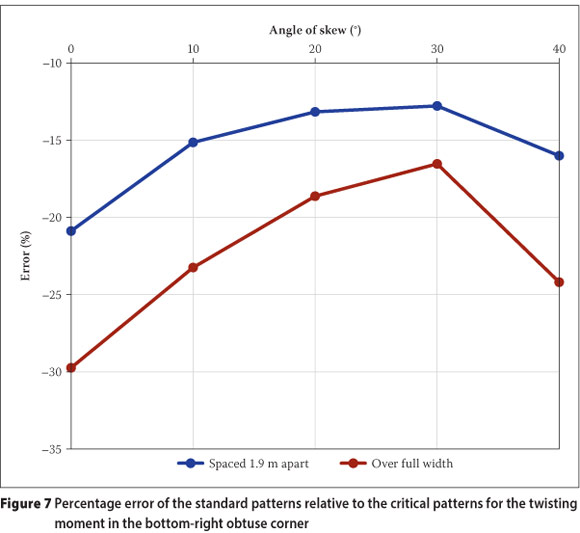
The comparative errors of the standard patterns relative to the critical patterns are presented in Figure 7. Both application methods of type NA loading were considered (see Figure 2), namely line loads spaced 1.9 m apart in combination with point loads, as well as uniformly distributed loads in combination with knife-edge loads over the full width of a notional lane. The errors are measured for angles of skew ranging from 0° to 40° in increments of 10°.
The critical NA loading patterns illustrated in Table 1 are not obvious. It is difficult to determine which parts of the notional lanes should be loaded and which parts provide a relieving effect, i.e. should not be loaded. Another difficulty, once the parts that should be loaded have been identified, is determining the position where the highest intensity loading should be applied.
It can be seen in Figure 7 that the standard loading patterns do not yield an acceptable result for the twisting moment in the obtuse corner. In the case of the standard patterns, all the loadable parts of a notional lane are loaded for a single-span carriageway (see Figure 3). This explains the large errors that occur between the standard values and the critical values, since areas that provide a relieving effect are also loaded. The largest error occurs at a 0° angle of skew, when the obtuse corner has not formed. At a 0° angle of skew, the values produced by the standard patterns are 21% and 30% smaller than those produced by the critical NA loading patterns for the line loads and distributed loads respectively. The errors decrease gradually up to an angle of skew of 30°. After 30° the errors increase again. As the angle of skew increases, the density of the twisting moment plots in the region of the obtuse corner also increases, as illustrated in Table 1. This indicates that the gradient of the twisting moment in the region of the obtuse corner increases as the angle of skew increases.
Transverse bending moment
The transverse bending moment is measured at mid-span at the centre of the carriageway (see Figure 6). The critical NA loading patterns and resulting bending moment contours for this case are presented in Table 2.
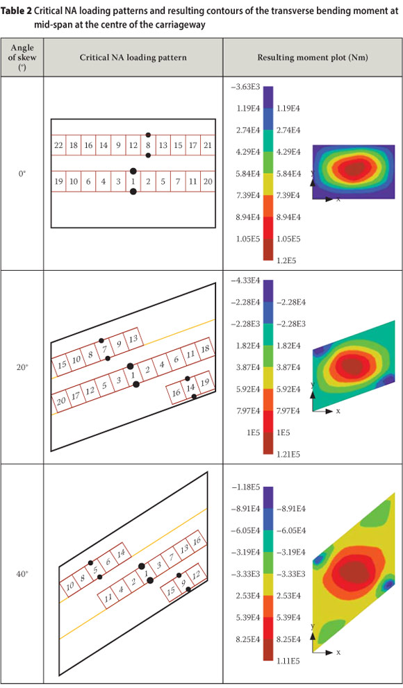
The following can be observed from Table 2 regarding the critical NA loading patterns for the transverse bending moment at mid-span, at the centre of the carriageway:
■ To produce the critical NA loading pattern, both the acute corners of the carriageway should not be loaded.
■ The highest intensity loading should be applied towards the centre of the carriageway in both the longitudinal and transverse directions, as expected.
Another observation from Table 2 is the concentration of the transverse bending moment in the obtuse corner when the angle of skew increases, even though the loading patterns were generated to produce critical values at mid-span and not in the obtuse corner. At a 40° angle of skew, the magnitude of the transverse bending moment in the obtuse corner exceeds its magnitude at mid-span.
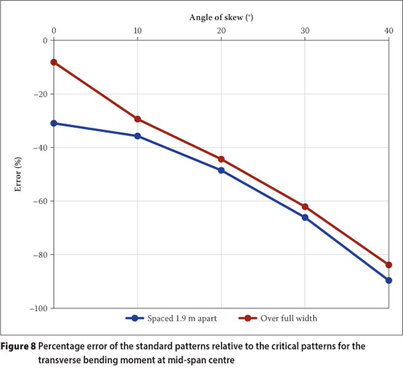
The comparative errors of the standard patterns relative to the critical patterns are shown in Figure 8. It can be seen that the standard NA loading patterns do not yield acceptable results for the transverse bending moment at mid-span, at the centre of the carriageway, especially at higher angles of skew. The standard patterns produce values up to 90% smaller than those produced by the critical patterns. The large errors are due to the fact that the effective area of the carriageway that should be loaded decreases as the angle of skew increases. Partial loading of notional lanes is not provided for by the standard NA loading patterns. As a result large areas that should not be loaded (so-called "areas of relief") are loaded by the standard patterns. This results in an increased error as the angle of skew increases.
Longitudinal bending moment
The longitudinal bending moment under consideration here is rotated to coincide with the angle of skew. The rotated longitudinal bending moment is measured at mid-span, at the bottom edge of the carriageway, i.e. M'21 shown in Figure 6. The corresponding critical NA loading patterns and resulting bending moment contours are illustrated in Table 3.
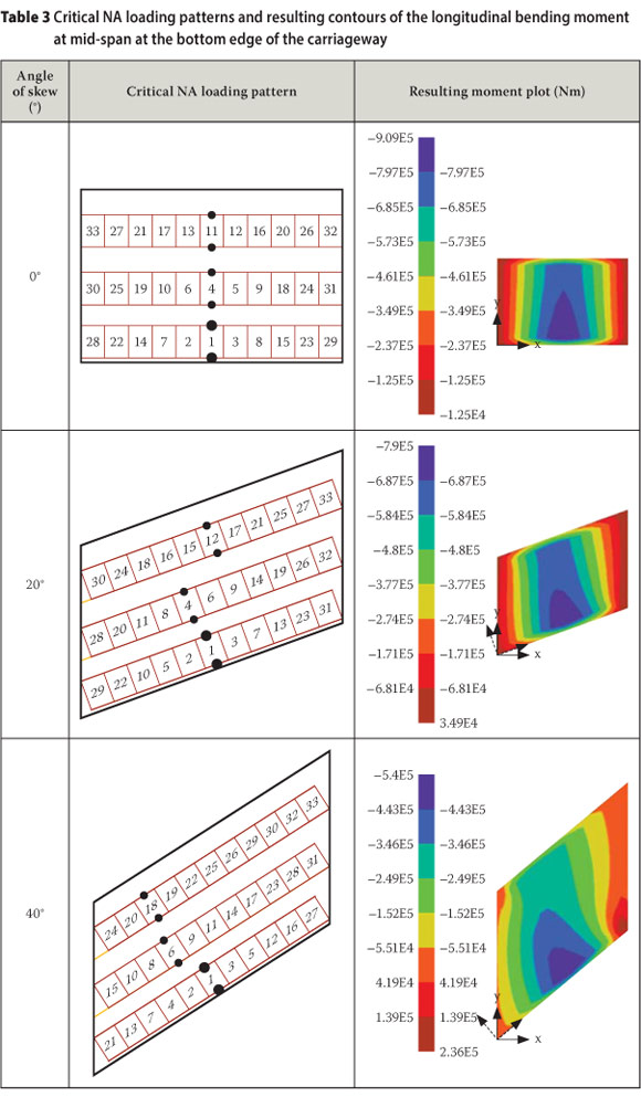
It is clear from Table 3 that the critical NA loading patterns for the longitudinal bending moment at mid-span, at the edge of the carriageway, are as expected for a singlespan deck:
■ All the loadable parts of the notional lanes are loaded.
■ The highest intensity loading is applied towards mid-span in the longitudinal direction and towards the bottom edge of the carriageway in the transverse direction.
As the angle of skew increases, the highest intensity loadings on the adjacent notional lanes are applied more towards the left edge, almost perpendicular to the direction of the carriageway. This can be ascribed to the rotated nature of the longitudinal bending moment vector and due to the fact that the patterns are generated for the edge of the carriageway and not for the centre.
The comparative errors of the standard patterns relative to the critical patterns are shown in Figure 9.
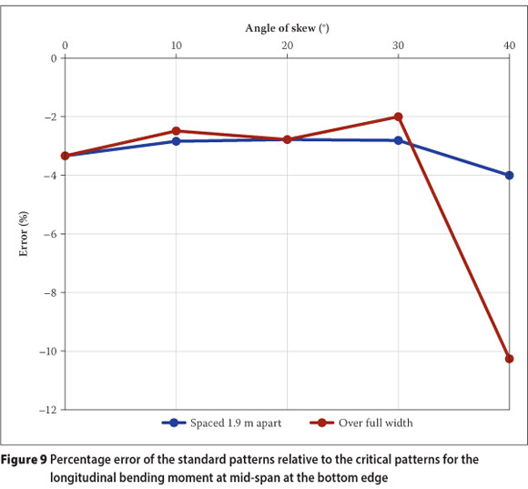
The standard loading patterns yield a good approximation of the critical longitudinal bending moment, especially for the application type where distributed line loads are used in combination with point loads. The values produced by the standard patterns are less than 4.5% smaller than those produced by the critical patterns for all the angles of skew, except for the 40° angle of skew and the application type where the load is distributed over the full width of the notional lanes. These small errors can be ascribed to the fact that both the standard and the critical patterns load the full loadable lengths of the notional lanes. The critical patterns only choose the loading sequences better, as indicated in Table 3.
Bridge deck behaviour
In order to gain insight into the overall flexural behaviour of the bridge deck, the different moment resultants described above are compared with each other. The different moment resultant values are normalised relative to the largest moment resultant in each of the selected design regions and then compared as shown in Figure 10.
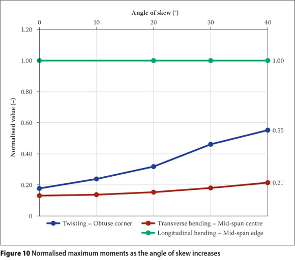
The following observations regarding the flexural behaviour of the particular bridge deck follow from Figure 10:
■ The rotated longitudinal bending moment at mid-span, at the edge of the carriageway, is the dominant moment resultant for all angles of skew.
■ The second-largest moment resultant is the twisting moment in the obtuse corner, reaching a value of 55% of the longitudinal bending moment at mid-span. The twisting moment resultant increases rapidly as the angle of skew increases.
■ The transverse bending moment at mid-span, at the centre of the carriageway, remains relatively constant as the angle of skew increases, with a relative value of approximately 16-20%.
CONCLUSIONS AND RECOMMENDATIONS
Critical NA loading patterns, complying with TMH7, were presented and compared with simplified, standard NA loading patterns for increasing angles of skew of a bridge deck. Only the flexural behaviour of the deck was investigated.
Critical normal traffic loading
It was shown that the critical NA loading patterns are not obvious, particularly for the twisting moments and transverse bending moments as the angle of skew increases. It is difficult to determine which parts of the carriageway should be loaded and which parts provide a relieving effect and should not be loaded. Another difficulty is determining the loading sequence, i.e. how to vary the loading intensity over the parts that should be loaded.
The results presented in this paper provide some guidelines regarding the area that should be loaded and the loading sequence. However, in general, specialised software is required to find the critical loading patterns, even for the single-span case considered here. It can be expected that for continuous multi-span carriageways the loading arrangements on the adjacent and alternate spans will not follow any clear pattern as the angle of skew increases.
Standard patterns and critical patterns
Simplified standard NA loading patterns were introduced. However, they did not provide good approximations of the twisting and transverse bending moment resultants in the selected design regions. In fact, large errors of up to 90% of the critical values were recorded. The only moment resultant for which the envelope of the standard patterns produced an acceptable approximation was the rotated longitudinal bending moment at the edge of the carriageway.
It is concluded that the standard patterns may be used to provide an approximation of the longitudinal bending moment at the edge of the carriageway. However, to obtain the critical moment resultants, especially the twisting and transverse moments, specialised software is required in order to perform rigorous distribution analysis.
Flexural bridge deck behaviour
For the case presented in this paper, the longitudinal bending moment at mid-span, at the edge of the carriageway, was the dominant moment resultant for all the angles of skew that were investigated. When the carriageway is not skew, the twisting and transverse bending moments are small relative to the longitudinal bending moment. However, as the angle of skew increases, the twisting and transverse bending moments increase relative to the longitudinal bending moment. Although the design is not necessarily done directly for the twisting moments, e.g. the incorporation of the twisting moments in the Wood and Armer (Wood 1968) design values, the twisting and transverse bending moments deserve more design consideration at larger angles of skew.
The k-factor of TMH7
The k-factor of TMH7 is a correction factor used to compensate for the effects of partial loading of parts of the influence lines (see Section 2.A.2.2 of TMH7). The complication arises from the fact that high-intensity loading of part of an influence line may result in a more severe effect than that caused by loading the whole base of the influence line at a lower intensity. With NA loading and an influence line base that exceeds 36 m in length, the challenge is to determine whether a more severe effect will be obtained if the whole base is loaded at reduced intensity, or whether just the peak of the influence line should be loaded at the full intensity of 36 kN/m. Figure 11 illustrates this problem.
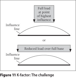
TMH7 introduces certain correction factors, called k-factors, to compensate for the effects illustrated in Figure 11. The k-factors depend on the tails of the influence lines and can be difficult to apply in practice. The procedure presented in this paper, with the incremental generation of critical NA loading patterns, provides a solution whereby the k-factor is no longer required. With the incremental generation of critical patterns, the area with the most severe effect, i.e. the peak of the influence line, will be loaded with the full intensity of type NA loading. The parts with decreasing influence values are loaded with correspondingly lower intensities, when these become applicable. The solution is illustrated in Figure 12.
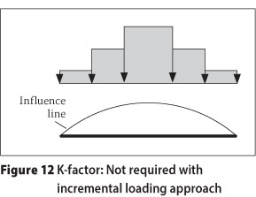
Although the procedure illustrated in Figure 12 is in contradiction to the definition of a separate loadable part (Section 2.6.3.2.1 of TMH7 states that a separate part is that continuous length of notional lane that has an entirely positive or negative effect on the member being analysed), the solution presented here eliminates the need for the k-factor. The procedure considers not only the positive or negative effect, but also the specific magnitude of the positive or negative effect, i.e. there is true optimisation of the information provided by the influence surface.
Recommendations for future work
In order to keep this paper detailed and focused, its scope was limited to critical normal traffic loading for flexure of skew bridges and only a single-span deck was considered. Multi-span, continuous decks were also investigated but are not reported on here. However, additional investigations still have to be done and they are briefly discussed below.
Additional types of traffic loading
Normal (NA) loading was investigated in this paper. Similar studies should be conducted for abnormal (NB) and super (NC) traffic loads.
Additional information for bridge designers
Future research should include additional information that is useful to bridge designers, including the determination of the following:
■ The impact on the dimensioning moments, using Wood, Armer, Kuyt or the French equations, specifically since most slabs are isotropic and the cracked stiffness may be different in the transverse and longitudinal directions.
■ The impact of elastomer bearings, specifically on hogging and torsion in the corners.
Code considerations
The current South African specification of TMH7 was written in 1981 and was last revised in 1988. By contrast, the Eurocode has undergone more recent upgrades. A comparative calibration analysis can be performed between the Eurocode and TMH7, similar to the comparative analyses performed in this investigation between the standard patterns and the critical patterns. Proposed adjustments to TMH7 can also be tested and compared with the current TMH7 by using the methods and software presented in this paper.
ACKNOWLEDGEMENTS
The authors wish to thank all the participating bridge engineers who provided valuable input throughout the course of the research. We also gratefully acknowledge the OSP funding from the University of Stellenbosch.
REFERENCES
Committee of State Road Authorities 1981. Code of Practice for the Design of Highway Bridges and Culverts in South Africa. TMH7 Parts 1 & 2, revised 1988. Department of Transport, Pretoria. [ Links ]
Hambly, E C 1976. Bridge Deck Behaviour. London: Chapman and Hall. [ Links ]
Wood, R H 1968. The reinforcement of slabs in accordance with a pre-determined field of moments. Concrete, 2(2): 69-76. [ Links ]
 Contact details:
Department of Civil Engineering, University of Stellenbosch
Private Bag X'
7602 Matieland
South Africa
T: +27 21 417 2923 F: +27 21 808 4947
E: andreas.malan@gmail.com
Contact details:
Department of Civil Engineering University of Stellenbosch Private Bag X'
7602 Matieland
South Africa
T: +27 21 808 4437 F: +27 21 808 4947
E: gcvr@sun.ac.za

ANDREAS MALAN holds a BEng degree in civi engineering and recently completed his MSc Eng degree in the field of Civil Engineering Informatics at Stellenbosch University. His research focused on the critical application of normal traffic loading on skew bridges according to the South African specification of TMHZ His research Interests Include bridge deck analysis, structural modelling and software development. He recently joined SMEC as a structural enigineer.

Dr G C VAN ROOYEN studied science anc engineering at the Universities of the Orange Free State, Pretoria and Stellenbosch, holding a PhD from the latter. He is currently responsible for Civil Engineering Informatics in the Department of Civil Engineering at Stellenbosch University. Before joining the lecturing staff at Stellenbosch in 1992 he worked as construction engineer for the Department of Water Affairs and as a researcher at the nstitute for Structural Engineering and the Bureau of Mechanica Engineering of the University of Stellenbosch.

