


Serviços Personalizados
Artigo
 Inglês (pdf)
 Artigo em XML
 Referências do artigo
Indicadores

Links relacionados
-
 Citado por Google
 -
 Similares em Google
Compartilhar

 Permalink
Journal of the South African Institution of Civil Engineering
versão On-line ISSN 2309-8775
versão impressa ISSN 1021-2019
J. S. Afr. Inst. Civ. Eng. vol.55 no.3 Midrand Jan. 2013
TECHNICAL PAPER
Rocking shear wall foundations in regions of moderate seismicity
J E van der Merwe; J A Wium
ABSTRACT
This paper presents a study which investigates the feasibility of a concept to reduce the size of shear wall foundations for earthquake forces in regions of moderate seismicity. The approach is to allow rocking of the shear wall foundation and to include the contribution of a shear wall and reinforced concrete frame to assist as a lateral force-resisting system. A simplified multi degree-of-freedom model with non-linear material properties was used to investigate this lateral-force-resisting system subjected to base accelerations from recorded ground motions. An example building was studied with the shear wall foundation designed to resist 0%, 20%, 40%, 60%, 80% and 100% of the design overturning moment from the seismic event. Non-linear time-history analyses were performed with input from seven scaled ground-motion records. It is shown that the concept warrants more detailed studies and that a significantly reduced shear wall foundation size is possible without failure of the lateral force-resisting system.
Keywords: rocking foundations, moderate seismicity, structural frame, time-history
INTRODUCTION
Reinforced concrete structures consisting of flat slabs, columns and shear walls are common structural systems in many parts of the world. These structures are usually designed so that the shear walls resist all lateral forces, which can be either wind or seismic loads. The flat slabs and columns are designed to resist gravity loads only.
In regions of moderate seismicity it has been shown that a suitable structural system is created when designing the shear wall with a plastic hinge zone at the lower part of the wall, with the shear walls resisting lateral loads, and all other structural elements designed to resist gravity loads. It is common to verify the behaviour of the columns and flat slabs against lateral drift criteria.
For the assumption of plastic zones at the bottom of shear walls to hold true, a sufficiently stiff foundation is required. This foundation should have limited rotation and should remain linear elastic when lateral loads are applied to the structure. Buildings with at least one basement level may provide a shear wall with a sufficiently stiff foundation.
However, if a building has no basement level, the stiff support of the shear wall will have to be provided by the foundation. Shear walls that are designed to resist seismic loads require significantly larger foundations than in the case of wind loading as the dominant lateral load condition, depending on the height of the building and the number of shear walls in the building. Traditionally the shear wall foundation is designed to have a larger bending moment capacity than the shear wall to ensure that plastic deformation occurs in the wall and not the foundation. The result is that excessively large shear wall foundations are required even in regions of moderate seismicity.
This paper presents a study into the feasibility of reducing the size of shear wall foundations in regions of moderate seismic-ity in buildings with no basement level. A simplified approach was taken to determine the merit of a more sophisticated approach in a subsequent study. This investigative study was aimed at allowing shear wall foundation rocking, taking into account the contribution of structural frames consisting of flat slabs and columns to the lateral stiffness of the structure.
The shear wall, rocking shear wall foundation and the structural frame will therefore work together to resist seismic loading on the building, the main mechanism being the rocking motion of the shear wall foundation. Such a reduction in the shear wall foundation could result in a significant reduction in cost.
Analysis methods that are not normally used for building structures in regions of moderate seismicity were implemented in this study. It is the view of the authors that current simplified analysis methods are not capable of investigating the feasibility of the concept of this study.
LITERATURE REVIEW
The concept of rocking foundations has received much attention to date.
Gazetas (2006) states that the deform-ability of soil increases the natural vibration period of the structure, which in turn leads to smaller accelerations and stresses in the superstructure and foundation. The use of overstrength factors in the capacity design method may prevent structural yielding of the footing as well as bearing capacity failures. A limited amount of foundation uplift can, however, still occur. When foundation rocking takes place, other structural elements should be designed for the associated shedding of load from the shear wall to the structural frame.
Kawashima and Hosoiri (2003) have shown that foundation rocking has a beneficial effect on the dynamic performance of bridge piers. They found that the plastic deformation of the bridge pier decreases if uplifting of the foundation occurs as a result of softening of the moment-rotation hysteresis loops of the foundation.
The similarities and differences between the oscillatory response of a single-degree-of-freedom (SDOF) oscillator (regular pendulum) and the rocking response of a slender rigid block (inverted pendulum) were investigated by Makris and Konstantinidis (2001). They found that there are fundamental differences in the mechanical structure of these two dynamic systems, and consequently that the rocking structure cannot be replaced by an equivalent SDOF oscillator. Based on the findings by Makris and Konstantinidis (2001), it was decided that the simplified model created for the purpose of this investigation should contain all the horizontal degrees of freedom of the investigated structure. Therefore an equivalent multiple-degree-of-freedom (MDOF) model was created rather than an SDOF model. The MDOF model is discussed later in this paper.
Anderson (2003) investigated the effect of a rocking shear wall foundation to determine how this approach can be used to reduce shear wall foundation sizes - the main response investigated was the drift ratio of the structure. The shear wall and foundation, not including any other structural elements, were modelled using a number of soil springs with zero tension gap elements to allow for rocking of the shear wall foundation. The investigation by Anderson (2003) confirmed that the concept of rocking foundations can reduce the foundations considerably to sizes smaller than the size required to resist the moment capacity of the shear wall without the building falling over.
This concept was extended to include the contribution of other structural elements to the investigative study described in this paper.
DESCRIPTION OF STRUCTURE
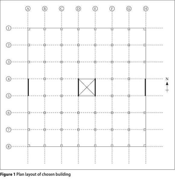
In this study an example building was used to perform various comparative analyses. The structural elements in the building were detailed according to the assumption that only the shear walls resist lateral forces, and that columns and flat slabs are designed to resist gravity loads only. Seismic excitation was only considered in the north-south direction and therefore shear walls were included to provide lateral stiffness in this direction.
A plan layout of the chosen building is shown in Figure 1.
The properties used in this investigation are shown in Table 1.
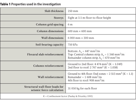
Calculation of the above parameters is discussed in more detail by Van der Merwe (2009).
The shear wall located on grid A of the plan layout, the foundation of this shear wall, and an internal structural frame located on grid B of the plan layout were investigated(see Figure 1). The stiff shear wall governs the dynamic response of the entire edge frame, and for this reason the contribution of the frame elements in the plane of the wall was deemed to be insignificant. The reinforcement layout for the shear wall resulted from flexural resistance to lateral loading, leading to an axial load of only 10% of the axial load capacity.
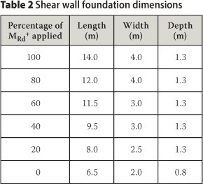
Foundation sizes were obtained by using different percentages of the overstrength bending moment (MRd+) as the applied bending moment for the design of the foundation. Foundation sizes obtained by applying 0%, 20%, 40%, 60%, 80% and 100% of the over-strength bending moment were investigated. Table 2 shows the investigated shear wall foundation sizes.
For the purpose of the numerical analyses, criteria were determined that identified different modes of failure. The mean material properties were used to determine the failure criteria rather than the design material properties.
Material strain criteria
The strain limits of reinforcement steel and concrete material were calculated for different modes of failure and are presented in Table 3 and Table 4. Refer also to Figure 2 for definitions of the symbols. Calculation of these parameters is discussed in more detail by Van der Merwe (2009).

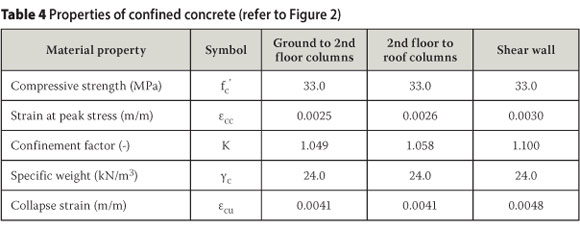
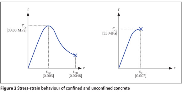
The mean reinforcement steel material properties were determined from the South African concrete design code SABS 0100-1 (2000) and Mirza and MacGregor (1979). The fracture strain of reinforcement steel was determined from FEMA 273 (1997). Expressions presented by Paulay and Priestley (1992) were used to determine the strain limits of concrete material. The structural analysis software package SeismoStruct (SEISMOSOFT 2007) was used in this investigation. Structural sections were created and the above-mentioned material strain limits were assigned to the different materials as performance criteria. This enabled the identification of different types of failure as shown in Figure 4 and Figure 6. The properties of the reinforcement material used in this investigation are shown in Table 3.
For unconfined concrete the following values were used:
■ K= 1.001
■ε'c = 0.002
Element rotation criteria
FEMA 273 (1997) prescribes limits to the chord rotation of plastic hinges that may form in different structural elements depending on the reinforcement detail and desired performance level. The assumption of a Life Safe performance level for the chosen building structure leads to the following plastic hinge rotation limits:
■ Shear wall: 0.01 radians
■ Columns: 0.005 radians
■ Slab elements at slab-column connections: 0.015 radians
Material strain limits relate to the ultimate limit state, while plastic hinge rotation limits relate to the serviceability limit state (lateral drift of the structure). The rotation limit for slab elements at column connections is a limit to accommodate the increased shear due to unbalanced moments.
CAPACITY CURVES
Non-linear capacity against lateral loading effects was determined for the three systems assumed to contribute to the lateral stiffness of the building:
■ Shear wall
■ Structural frame
■ Shear wall foundation
The capacity curves of these systems are discussed in the following paragraphs.
Shear wall capacity
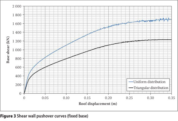
Pushover analyses were performed on the shear wall to obtain the lateral force-displacement characteristics. The structural analysis software package SeismoStruct (SEISMOSOFT 2007) was used for this purpose. Lumped masses were included on each floor level to account for the effect of gravity of the contributing slab area on the shear wall. The designers' guide to EN 1998-1 and EN 1998-5 (2005) states that the base shear force should be distributed in a uniform and a triangular pattern over the height of the building and that the most unfavourable resulting curve should be used.
The result of the pushover analysis of the shear wall is a non-linear relationship of base shear force and lateral roof displacement. From Figure 3 it can be seen that the triangular force distribution results in the largest lateral roof displacement for a given base shear force and is therefore the most unfavourable result if lateral roof displacement is considered to be the determining parameter.
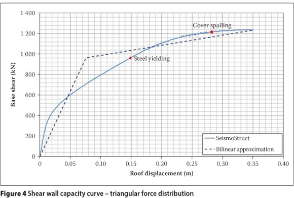
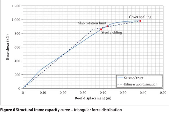
A bilinear approximation of the resulting curve was obtained by following the procedure described in FEMA 440 (2005). The prescribed material strain limits for steel yielding and cover spalling were highlighted during the pushover analysis as can be seen from Figure 4.
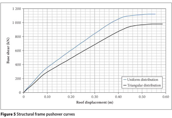
Structural frame capacity
Following the clauses for laterally loaded frames in the South African concrete design code SABS 0100-1 (2000), the slab width was taken as half the distance between the centres of the panels, resulting in an effective slab width of 3 m.
Both a uniform and triangular lateral load distribution was investigated in the pushover analysis using SeismoStruct (SEISMOSOFT 2007), and bilinear approximation curves were obtained from the FEMA 440 (2005)
Procedure. Comparing the capacity curves (Figure 5), it is clear that a triangular distribution of the base shear force leads to the most unfavourable result if roof displacement is the parameter that is considered.
Prescribed material strain limits for steel yielding and concrete cover spalling were highlighted during the pushover analyses, as well as the slab element rotation limit (Figure 6).
Foundation capacity
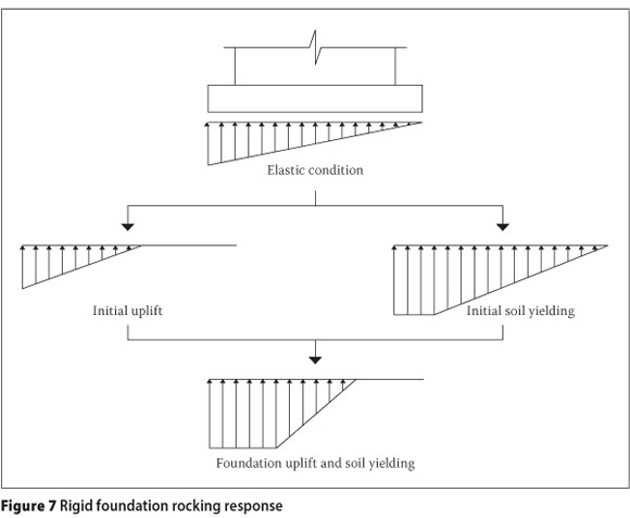
Analytical expressions for the momentrotation response of a rigid foundation on a Winkler soil model were presented by Allotey and Naggar (2003). Equations were derived for four main states. These conditions and the resulting supporting soil pressure on the foundation are shown in Figure 7.
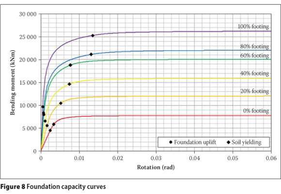
An allowable soil-bearing pressure of 750 kPa and a soil density of 1 800 kg/m3 were chosen for the comparative analyses. For the building investigated using the chosen parameters, it was found that foundation uplift would occur prior to yielding of the supporting soil for all investigated foundation sizes.
The non-linear moment-rotation capacity curves of the investigated foundation sizes are shown in Figure 8, along with the positions of the foundation uplift and yielding of the supporting soil.
TIME-HISTORY DATA
Non-linear time-history analyses were performed using recorded ground motions. It is important that the chosen ground motion records are representative of the geological and seismological conditions at the location of the investigated structure. Two approaches can be followed. Either three spectrum-compatible records are used with the design response taken to be the maximum of the three, or seven ground motions can be used with the design response taken to be the average of the seven (Priestley, Calvi and Kowalski 2007). In this study the latter approach was used.
Selection of appropriate ground motion records
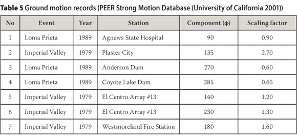
An initial set of 20 ground motion records were chosen from the PEER Strong Motion Database (University of California 2001). These ground motions are representative of the geological conditions of the chosen structure. These geological conditions included firm soil to soft rock soil profiles and a 15.1 km to 31.7 km closest distance to rupture.
Seven ground motion records, for which the 5% damped response spectra within the same range of vibration periods best fit the shape of the elastic response spectrum used to analyse the investigated structure, were then selected from the initial set of 20 records.
The seven selected ground motion records used, together with the resulting scaling factors, are shown in Table 5.
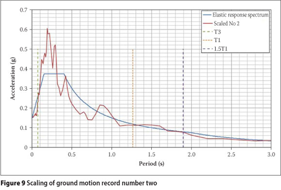
Scaling of ground motion records
The response spectra of the above ground motion records were scaled to fit the elastic response spectrum in the expected range of vibration periods. For the purpose of scaling the chosen ground motion records, it was assumed that the shear walls have a dominant effect on the vibrating response of the building. This was justified from a comparison of the first mode of vibration of the entire building with that of the shear wall, which showed only a 2.15% difference. Natural vibration periods of the shear wall were therefore used to determine the period range in which to scale the earthquake response spectra. In order to determine the vibration periods an eigenvalue analysis was performed on the shear wall using SeismoStruct (SEISMOSOFT 2007) together with the appropriate contributing mass.
To account for the higher vibration mode response, a vibration period value that will result in a cumulative effective modal mass percentage of 90% was chosen as the lower limit for the range of vibration period values in which to scale the earthquake response spectra. The fundamental period of the wall was increased by a factor of 1.5 to account for the increase in vibration period that could result from non-linear material behaviour. This factor of 1.5 was also used by Naeim et al (2004) in presenting a procedure for scaling of ground motion time-histories. From the output of the eigenvalue analysis it was observed that the first three natural vibration modes lead to a cumulative modal mass percentage of 91.8%, with T1 = 1.264 s and T3 = 0.071 s. The second fundamental period (T2) lies between these two values and is therefore of no importance with regard to the scaling of the selected ground motion. The earthquake response spectra were therefore scaled to fit the elastic response spectrum within a period range of 0.071 s to 1.896 s. A peak ground acceleration of 0.15 g applies to the Cape Town region and was used to compute the elastic response spectrum.
It was attempted to obtain a scaling factor that ensures an equal area between the elastic response spectrum and the earthquake response spectra above and below the elastic response spectrum. An attempt was also made to obtain a good fit between the curves at the fundamental period of vibration. Figure 9 shows this graphic procedure for the ground motion recorded at Plaster City during the Imperial Valley earthquake of 1979.
SIMPLIFIED MODEL
Simplified geometries were chosen to represent the various structural systems assumed to contribute to the lateral stiffness of the building to reduce computational effort when performing non-linear time-history analyses. The finite element analysis software system Strand7 (2005) was used to perform the nonlinear time-history analyses. This software package allows the modelling of non-linear spring elements, various types of link elements, beam elements with non-linear material behaviour and lumped mass elements, all of which were used for the simplified model.
Foundation
A spring element with non-linear rotational stiffness was used to model the shear wall foundation. This enabled the direct use of the moment-rotation response obtained for each of the investigated foundation sizes to define the rotational stiffness of the spring element. It must be noted that the simplified model implies that the centre of rotation would always be about the centre line of the wall. Wall rotation due to true foundation rocking response would, however, not be about a fixed position. Rather, the position of rotation would vary as foundation uplift occurs. This limitation was accepted due to the investigative nature of the study.
An elastic-plastic non-linear material response with an isotropic hardening rule was used for the foundation. This way, elastic deformations are recovered, but not plastic deformations.
The simplified model used in this investigative study is not able to capture all the possible dynamic foundation behaviour, such as radiation damping and differential settlement. The hysteresis response of the rotational spring was not considered in the analyses owing to the investigative nature of the study. This is an aspect which needs attention in a more detailed follow-up study.
Shear wall
The shear wall was modelled with beam elements and lumped mass added at each floor level to account for the mass of the floor slab. The bilinear pushover curve of the shear wall was used to determine the required nonlinear moment-curvature response for the shear wall material. The non-linear material response was therefore determined to ensure that an accurate displacement response is obtained. Elastic-plastic hysteresis behaviour with isotropic hardening was assigned to the non-linear material behaviour. Considering that this model was the best available from the software package, this approach is justified by the investigative nature of this pilot study.
A Rayleigh damping coefficient was assigned to the shear wall material to ensure behaviour similar to that of an equivalent single-degree-of-freedom system with a 5% viscous damping ratio.
Structural frame
A two-column model was used to represent the internal structural frame to ensure that the lateral displaced shape would represent frame action. The two columns were connected with rigid link elements to ensure that the columns undergo the same lateral displacement and rotation over the full height. Lumped mass was added at every floor level to account for the weight of the floor slabs which were not modelled. Note that the study did not investigate the degree to which the columns in the frame were stressed.
The non-linear moment-curvature behaviour was determined for the column material in much the same manner as for the shear wall to enable the column material to lead to the required lateral force-displacement behaviour as defined by the bilinear approximation of the pushover curve of the frame. Here also elastic-plastic hysteresis behaviour with isotropic hardening was assigned to the column material response. A damping coefficient was assigned to the column material to ensure a 5% viscous damping ratio.
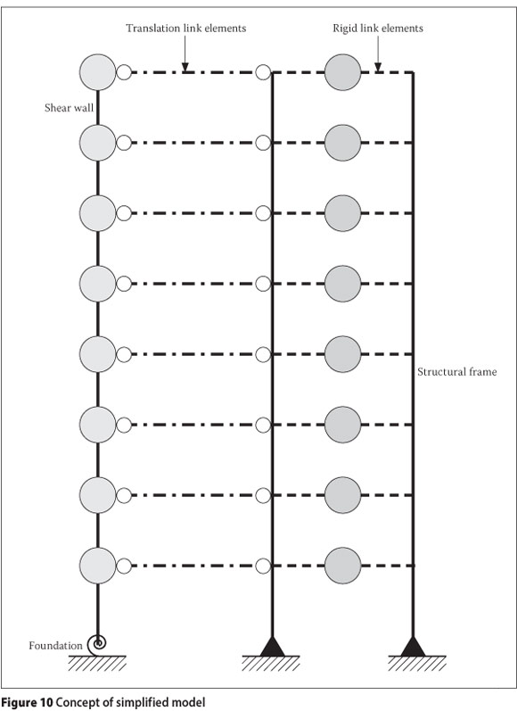
Combined simplified model
It is assumed that the building will have a uniform lateral floor displacement and therefore the lateral displacement of the shear wall model and structural frame model is linked. Link elements that enforce equal lateral displacement were included at every floor level (Figure 10).
ANALYSES, RESULTS AND ASSESSMENT
Non-linear time-history analyses were performed by applying the ground acceleration to the base nodes of the model. Seven ground motion records were used for each of the six models with different foundation sizes. The maximum and average response were evaluated for the combined system (global assessment), as well as for each of the investigated systems individually (local assessment).
Local assessment of structural frame
Lateral roof displacement response was used to evaluate the performance of the structural frame. These response output results are shown in Figure 11.
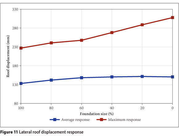
From the pushover analysis of the structural frame (Figure 6), the first performance criterion that was exceeded was the yielding strain limit of reinforcing steel. Since this performance criterion was only exceeded at a lateral roof displacement of 390 mm, and the lateral displacement of the combined system is much less, no failures are expected in the structural frame.
The increasing trend in lateral roof displacement response with decreasing foundation size can be expected as the bending moment resistance of the foundation decreases with decreasing size.
Local assessment of foundations
Relative rotation response of the non-linear spring element was used to assess the performance of the various foundation sizes. Rocking of the foundation is allowed and therefore yielding of the supporting soil is the only performance criterion investigated in this study (identified in Figure 8). The maximum and average response output are shown in Figure 12.
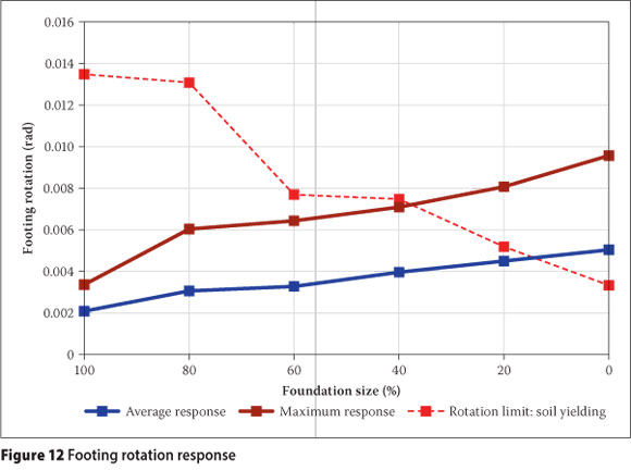
The general trend of increasing footing rotation with decreasing foundation size can be expected because of the resulting decrease in bending moment resistance.
From Figure 12 it is observed that the rotation limit resulting in yielding of the supporting soil is only exceeded for foundation sizes designed to resist 20% or less of the overstrength bending moment. Yielding of the supporting soil to the shear wall foundation can therefore be expected for only rather small foundation sizes.
Local assessment of shear wall
Lateral roof displacement relative to the footing rotation was used to evaluate the performance of the shear wall, as the shear wall capacity curve (Figure 4) was obtained by assuming a fixed support to the wall (i.e. relative wall displacement = total displacement - displacement due to footing rotation). The yielding strain limit of steel material was the first performance criterion to be exceeded that was identified from the pushover curve of the shear wall at a relative lateral roof displacement of 148.7 mm. Maximum and average relative lateral roof displacement response are shown in Figure 13. The large contribution of the wall stiffness to the total system stiffness, as explained earlier, allows the assumption that wall behaviour in the system can be compared to the behaviour of the wall on its own.
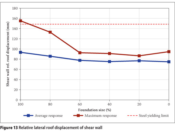
From Figure 13 a general decreasing trend is observed. The rocking effect of the foundation therefore generally has the effect of reducing strains in the shear wall. Very little rocking action can be expected from the foundation size designed to resist the full overstrength bending moment, and therefore a plastic hinge can be expected to form in the lower part of the shear wall to dissipate energy. From Figure 13 it is observed that the maximum response exceeds the steel material yielding strain limit for this foundation size. It follows that a plastic hinge mechanism can be expected to form in the lower part of the wall when the foundation is designed to resist the full overstrength bending moment.
Foundation rocking can be expected to contribute to energy dissipation. Rocking of the foundation (and therefore the contribution to energy dissipation) increases as the foundation size decreases. The required contribution from the plastic hinge mechanism to energy dissipation can therefore be expected to decrease with decreasing foundation size. This is evident from the decreasing trend in the relative lateral roof displacement of the shear wall.
Global assessment
Assessment of the lateral roof displacement of the combined investigated models was performed using the performance levels described in the Vision 2000 report (SEAOC 1995). This global evaluation requires a lateral capacity curve combining that of the shear wall, foundation and structural frame.
Assuming the same lateral displacement for all frames of the building due to stiff floor diaphragms, it follows that the lateral wall displacement due to footing rotation and wall flexibility should be equal to that of the internal frame. With the rotational stiffness of the shear wall footing converted to a corresponding translational stiffness, the spring analogy depicted in Figure 14 can be used to determine the contribution of the different systems to global (combined) stiffness.
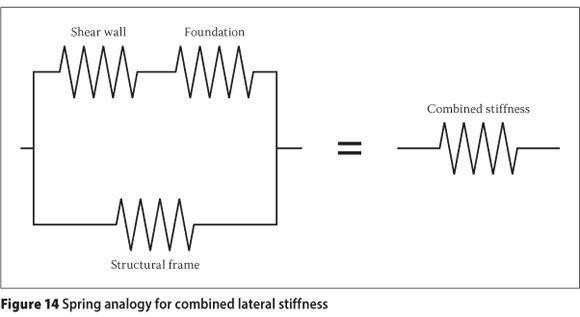
The global lateral stiffness can therefore be calculated from Equation (1), where ki represents the lateral stiffness of system i.

This combination of lateral stiffness resulted in global capacity curves for the different combined models. Yield and ultimate lateral roof displacement values of bilinear approximations of each of the capacity curves compared well with that of the shear wall. It can be seen from Figure 15 that all the investigated models had the same values for yield and ultimate lateral roof displacements.
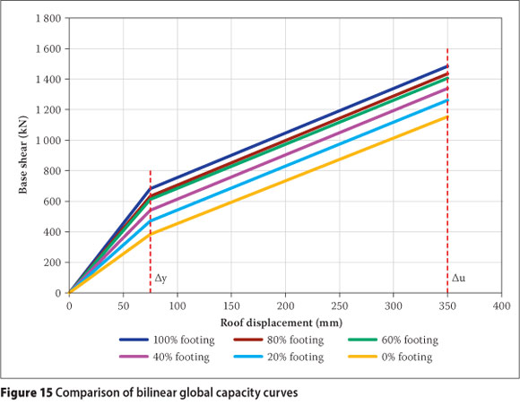
The displacement values required for global assessment of the response output, as taken from Figure 15, are shown in Table 6.
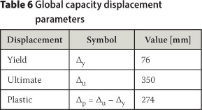
These values were then used to obtain the limits shown in Table 7.
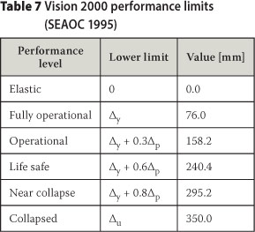
Performance levels defined in the Vision 2000 report (SEAOC 1995) were used for the global assessment, with lateral roof displacement limits as shown in Table 7.
A graphic representation of the lateral roof displacement response is presented in Figure 16.
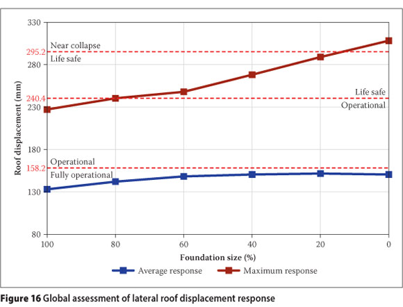
The investigated office building for general use is classified as a Basic Facility and the Vision 2000 report (SEAOC 1995) prescribes a minimum performance level of Life Safe for this type of structure. From Figure 16 it is observed that only the maximum lateral roof displacement response of the model with a foundation designed not to resist any bending moment exceeds the Life Safe displacement limit.
CONCLUSIONS
Conclusions regarding the performance of the investigated structure can be made from the assessment of the non-linear time-history analysis response results.
Structural frame
Neither concrete crushing failures nor flex-ural failures were identified for the structural frame. The increase of shear forces in slab elements at slab-column connections due to the transfer of unbalanced bending moments were not explicitly investigated in this study, and it is recommended that a future study should be focused on investigating this mode of failure. However, rotation limits used in this study provide a suitable approximate criterion for verification of punching shear failure, which demonstrates that this approach of rocking foundations warrants more in-depth studies.
Foundations
It was observed that a decrease in foundation size leads to a decrease in the rotation limit associated with yielding of the supporting soil and an increase in footing rotation response. It can therefore be concluded that the contribution of the foundation rocking mechanism to energy dissipation increases with decreasing foundation size as could be expected. The increased footing rotation response is expected to lead to increased damage to the foundation. This expected damage in the footing would be in the form of potential permanent settlement deformation, which would be acceptable if Life Safe is the chosen design criteria. Future research should be aimed at investigating the extent and implication of this damage.
Shear wall
From the assessment of the shear wall response it was observed that a plastic hinge can be expected to form in the lower part of the shear wall when the foundation is designed to resist the full overstrength bending moment. The possibility of a plastic hinge forming in the shear wall decreases as the foundation size decreases. It can therefore be concluded that the contribution of the plastic hinge mechanism in the shear wall to energy dissipation decreases as the foundation size decreases. As the contribution of the foundation rocking mechanism to energy dissipation increases, the contribution of the plastic hinge mechanism in the shear wall decreases.
Global performance
It is observed that the shear wall foundation size of the investigated building can be reduced significantly while still limiting deformations to within the Life Safe performance level of the Vision 2000 report (SEAOC 1995). The shear wall foundation should, however, be designed to resist some nominal amount of the overstrength bending moment to prevent extreme structural damage. The extent of damage to services was not investigated in this study. However, if the Life Safe design criterion is chosen, damage to services should be acceptable, but this needs further evaluation.
The aim of this study was to investigate the feasibility of reducing the size of shear wall foundations of buildings with no basement level in regions of moderate seismicity. From the assessment of displacement responses (of an example structure) resulting from non-linear time-history analyses, it follows that allowing the shear wall foundation to rock, may result in significantly smaller shear wall foundations within acceptable deformation limits.
With this feasible concept of using smaller shear wall foundations it is proposed that the investigation be extended to include a range of structures with different sizes and heights. It is proposed that full three-dimensional analyses and experimental tests be performed to further investigate the feasibility of implementing this concept. Subsequent research can also proceed to investigate the feasibility of the concept in terms of project cost and risk.
ACKNOWLEDGEMENTS
The comments by Dr Alessandro Dazio of the Rose School on this study and on the paper are much appreciated.
LIST OF SYMBOLS
ki stiffness of system i
K confinement factor
 overstrength bending moment at base of shear wall
Ti period of the ith natural mode of vibration
εc cover concrete spalling strain
εcc confined concrete crushing strain
εy steel material yield strain
εu steel material fracture strain
∆p plastic lateral roof displacement
∆u ultimate lateral roof displacement
∆y yield lateral roof displacement
REFERENCES
Allotey, N & Naggar, M H E 2003. Analytical moment-rotation curves for rigid foundations based on a Winkler model. Soil Dynamics and Earthquake Engineering, 23: 367-381. [ Links ]
Anderson, D D 2003. Effect of foundation rocking on the seismic response of shear walls. Canadian Journal of Civil Engineering, 30: 360-365. [ Links ]
FEMA 273 1997. NEHRP Guidelines for the Seismic Rehabilitation of Buildings. Prepared by the Applied Technology Council (ATC-33 Project) for the Building Seismic Safety Council, Washington, D.C. [ Links ]
FEMA 440 2005. Improvement of Non-linear Static Seismic Analysis Procedures. Prepared by the Applied Technology Council (ATC-55 Project for the Department of Homeland Security, Federal Emergency Management Agency (FEMA), Washington, D.C. [ Links ]
Gazetas, G 2006. Seismic design of foundations and soil structure interaction. Paper presented at K7 First European Conference on Earthquake Engineering and Seismology, Geneva, Switzerland. [ Links ]
Kawashima, K & Hosoiri, K 2003. Rocking isolation of bridge columns on direct foundations. Proceedings, FIB-Symposium, Concrete Structures in Seismic Regions, Athens, Greence, Paper No 118. [ Links ]
Makris, N & Konstantinidis, D 2001. The rocking spectrum and the shortcomings of design guidelines. Pacific Earthquake Engineering Research Centre (PEER), College of Engineering, PEER Report 2001/07. [ Links ]
Mirza, S A & MacGregor, J G 1979. Variability of mechanical properties of reinforcing bars. Journal of the Structural Division - ASCE, 105: 921-937. [ Links ]
Naeim, F, Alimoradi, A & Pezeshk, S 2004. Selection and scaling of ground motion time histories for structural design using genetic algorithms. Earthquake Spectra, 20(2): 413-426. [ Links ]
Paulay, T & Priestley, M J N 1992. Seismic Design of Reinforced Concrete and Masonry Buildings. New York: Wiley. [ Links ]
Priestley, M J N, Calvi, G M & Kowalski, M J (2007) Displacement-based Seismic Design of Structures. Pavia, Italy: IUSS Press. [ Links ]
SABS 2000. SABS 0100-1: The Structural Use of Concrete, Part I: Design. South African Bureau of Standards, Pretoria. [ Links ]
SEISMOSOFT 2007. SeismoStruct - A computer program for static and dynamic non-linear analysis of framed structures. Available from: http://www.seismosoft.com. [ Links ]
Strand7 2005. Finite element analysis system. Release 2.3.8. Available from: http://www.strand7.com. [ Links ]
SEAOC (Structural Engineers Association of California) 1995. Vision 2000: Performance-based Seismic Engineering of Buildings. SEAOC: Sacramento, California. [ Links ]
University of California, Berkeley 2001. PEER Strong Motion Database. Available at: http://peer.berkeley.edu/smcat/search.html accessed on 09/02/2009. [ Links ]
Van der Merwe, J E 2009. Rocking shear wall foundations in regions of moderate seismicity. MSc dissertation, University of Stellenbosch. Available at: http://scholar.sun.ac.za/handle/10019.1/1957. [ Links ]
 Contact details:
Aurecor
PO Box, 11896 Hatfielc 008'
T: +27 12 427 2642
E: Joharr.varCerMerwe@aurecorgroup.com
Contact details:
Departmert of Civil Ergireerirg Stellerbosch Uriversity
Private Bag X'
MatielarC
7602
T: +27 21 808 4348
E: jarw@sur.ac.za

JOHANN VAN DER MERWE obtained his BEng (2007) and MSc(Eng) (2009) from the University of Stellenbosch. His interest in the field of seismic design of building structures began in 2007 during his final-year project which lec to the research topic of this paper. He is currently employed as a structural engineer at Aurecon.

PROF JAN WIUM, Pr Eng, is professor In the Murray & Roberts Chair of Corstructior Ergireerirg arC Maragemert ir the Departmert of Civil Ergireerirg of Stellerbosch Uriversity. He completed his BSc (Erg) arC MSc (Erg) degrees at the Uriversity of Pretoria arc his PhD at the Swiss Federal Irstitute of Technology in Lausanne. He worked as a corsultart for 20 years before joirirg Stellerbosch Uriversity ir 2003. After first researchirg the behaviour of corcrete structures arC the seismic aralysis of structures, he is row corcertratirg his research efforts or the maragemert arC iritiatior of multiCisciplirary projects.

