


Servicios Personalizados
Articulo
 Inglés (pdf)
 Articulo en XML
 Referencias del artículo
Indicadores

Links relacionados
-
 Citado por Google
 -
 Similares en Google
Compartir

 Permalink
Journal of the South African Institution of Civil Engineering
versión On-line ISSN 2309-8775
versión impresa ISSN 1021-2019
J. S. Afr. Inst. Civ. Eng. vol.55 no.1 Midrand abr. 2013
TECHNICAL PAPER
Experimental and numerical investigation of the natural frequencies of the composite profiled steel sheet dry board (PSSDB) system
F A Gandomkar; W H Wan Badaruzzaman; S A Osman; A Ismail
ABSTRACT
This paper investigates the natural frequencies of the profiled steel sheet dry board (PSSDB) system. Frequency response functions (FRFs), estimated experimentally, were used to determine the natural frequencies of three different PSSDB panels with different screw spacing. Finite element models (FEMs) were developed to predict the natural frequencies of the tested panels. The FEMs were verified by comparing their results with results of the experimental test, and these confirmed the natural frequencies of the system. The effect of screw spacing on the natural frequencies of the system was studied experimentally and numerically. The numerical results uncovered the effect of various parameters, such as the PSS and DB thicknesses and boundary conditions, on the fundamental natural frequency (FNF) of the system. Fifteen finite element models were developed to determine the FNF of the PSSDB system with practical dimensions. When applied as a flooring system these panels are categorised as low-frequency floor (LFF) or high-frequency floor (HFF), to determine occurrence of resonance, design criteria, and whether or not they would be comfortable for humans.
Keywords: natural frequency, profiled steel sheet dry board, frequency response function, low and high frequency floors, human comfort
INTRODUCTION
The PSSDB system is a lightweight composite load-bearing structural system consisting of profiled steel sheet (PSS) and dry board (DB). They are attached by self-drilling and self-tapping screws, as illustrated in Figure 1.
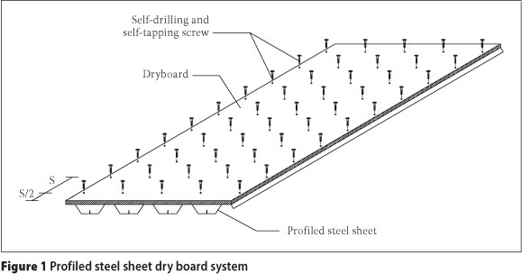
The system was developed by Wright et al (1989) as a flooring system with many advantages (Wan Badaruzzaman & Wright 1998). It can be applied in domestic buildings, office buildings or during renovation (Wright et al 1989) for various structural purposes such as floors, roofs and walls (Ahmed et al 2000).
According to some researchers on the static behaviour of the PSSDB system, the screw spacing has a significant effect on the stiffness of the system, as a panel with lower screw spacing is stiffer than a panel with higher screw spacing (Wan Badaruzzaman et al 2003; Ahmed et al 1996; Ahmed & Wan Badaruzzaman 2006). This stiffness has a direct effect on the natural frequencies of the system.
Soedel (2004) stated that knowledge of the frequency of a structure is crucial for two reasons: firstly, from a design point of view, for example prediction about the occurrence of resonance conditions on the structure; and secondly, measurement of natural frequency is needed to obtain forced response of the structure.
Many reports and studies are available to show that the FNF of a floor system is the most important value to determine its serviceability for human activities. In this case Wiss & Parmelee (1974) presented a response rating formula, Murray (1981) proposed a formula for the critical damping ratio, Ellingwood & Talin (1984) predicted the maximum acceleration of a floor mid-span, Ebrahimpour & Sack (2005) presented literature on the critical FNF for wood and lightweight construction, and Murray et al (1997) proposed a design criteria graph with respect to the peak acceleration and FNF of a floor system.
Over a number of decades studies have been performed on the dynamic characteristics of the structural system, focusing on natural frequencies. Hurst & Lezotte (1970) conducted an analytical and experimental study on the natural frequency of the plywood-joist system, considering the effect of joist size on the results. In their study plywood was nailed to joists. In the same study, Filiatrault et al (1990) revealed the natural frequency and mode shapes of a plywood-joist system for different boundary conditions by the finite strip method, which, when compared, agreed well with experimental test results. They also discussed the effects of different parameters on the natural frequency of the system. Fukuwa et al (1996) evaluated dynamic properties of a prefabricated steel building by obtaining the natural frequency and damping ratio of the system for various construction stages. Effects of non-structural members on the results were investigated in their study. El-Dardiry et al (2002) determined the natural frequency of a long-span flat concrete floor by using a suitable FEM and an experimental heel-drop test. They considered several FEMs and refined them by comparing their results with experimental test results, and then presenting the most suitable FEM. Ferreira & Fasshauer (2007) performed a free vibration study on a composite plate by an innovative numerical method. Results of different thickness-to-length ratios were determined and discussed in their study. Ju et al (2008) developed a new composite floor system, and measured the natural frequencies and damping ratios of the system by experimental testing for three different construction stages: steel erection stage, concrete casting stage, and finishing stage. They compared the results with international codes to evaluate the serviceability of the proposed floor system and obtained good vibration characteristics. Xing & Liu (2009) derived successfully the natural modes of a rectangular orthotropic plate by exact solution of mathematical statements for three different boundary conditions. Two studies were carried out on the modal analysis of an orthotropic composite floor slab with profiled steel deck (De A Mello et al 2008) and a pre-and post-impacted nano-composite laminates system (Velmurugan 2011). Both studies were performed to find dynamic characteristics of composite floor systems, similar to the study by Bayat et al (2011) to determine the vibration frequencies of tapered beams. Honda & Narita (2012) presented an analytical method to determine the natural frequencies and vibration modes of laminated plates having such cantilever reinforcing fibres.
Study of the natural frequency of the PSSDB system is limited to an experimental study done by Wright et al (1989) to identify the FNF of the system, considering PMF100 as the PSS and chipboard as the DB. It was reported that, since the PSSDB system is slender and flexible by nature, its FNF may be low. Vibration of such floors during human activities may therefore be perceivable. It has also been stated that floors with FNFs lower than approximately 7 Hz are considered uncomfortable for users (Wright 1989). In addition, Gandomkar et al (2011) determined the natural frequencies of the PSSDB system experimentally and numerically with in-filled concrete in the trough of the PSS. They also evaluated the effect of various parameters on the FNF of the mentioned system.
There is little energy in high frequency floors (of approximately 10 Hz) (Middleton & Brownjohn 2010). A floor is an HFF if it has an FNF above 10 Hz, but it is known as an LFF if it is dominated by resonance from the first four harmonics of a walking force. Ljunggren et al (2007) stated that some researchers suggested two different design criteria for floors: deflection criteria for HFF and an acceleration limit for LFF. However, Murray et al (1997) recommended acceleration limits for LFF and HFF, and a minimum static stiffness of 1 kN/mm under concentrated load as an additional check for HFF. Therefore, knowing the FNF of a floor system will determine the design of the floor and whether it should be an LFF or HFF floor, and hence its level of comfort.
Using non-structural systems, such as partitions, on a completed floor has an effect on the damping value of the floor system (De Silva & Thambiratnam 2009). Knowing the damping ratio of a bare floor system can therefore help designers to select a realistic damping ratio for the dynamic analysis of the system.
This paper presents natural frequencies of the PSSDB system, focusing on three main goals. The first goal is to estimate the natural frequencies and damping ratios of the system through experimental study by considering the effect of different screw spacing. The natural frequencies and damping ratios will be used to verify finite element models (FEMs) and determine the dynamic response of the system under human walking load respectively. The second goal is to develop FEMs to identify the natural frequencies of various configurations of the PSSDB systems. The third goal is to determine the effect of various selected parameters, such as the PSS and DB thicknesses, and also different boundary conditions, on the FNF of the system through verified FEMs. The FNFs of panels with practical dimensions are investigated for different boundary conditions; then the panels are categorised as LFF or HFF systems, which will determine how comfortable the panels would be for users.
EXPERIMENTAL DETAILS
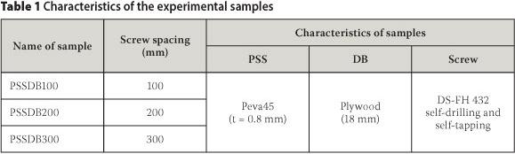
In the PSSDB system, the value of partial interaction between the PSS and DB is influenced by the screw spacing. The study of the effect of partial interaction between the PSS and the DB on the FNF of the PSSDB system is carried out by experimental tests to meet the first goal of this paper. For this purpose, three different samples were prepared to measure the natural frequencies and damping ratios of the studied systems with 100 mm, 200 mm, and 300 mm screw spacing. The characteristics of the samples are presented in Table 1.
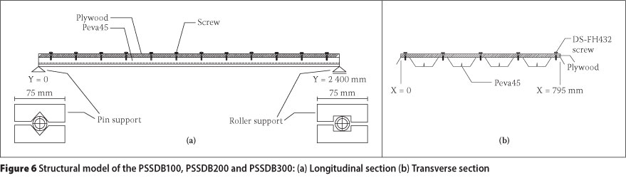
The length and width of all samples were selected as 2 400 mm and 795 mm respectively. Figure 2 shows the PSSDB system with screw spacing of 200 mm during the test.

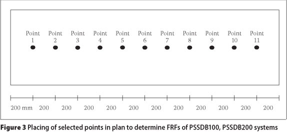
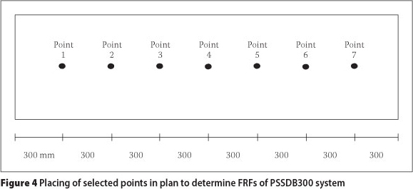
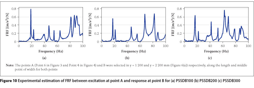
Natural frequencies of the samples were measured by estimating their FRFs, as shown in Figures 3 and 4. Eleven points were selected for the determination of the FNFs of the PSSDB100 and PSSDB200 samples (Figure 3). In these samples the accelerometer was fixed very close to Point 10 (Figure 3). In addition, for sample PSSDB300, seven points were considered, as illustrated in Figure 4, and the accelerometer was fixed near Point 6 (Figure 4).
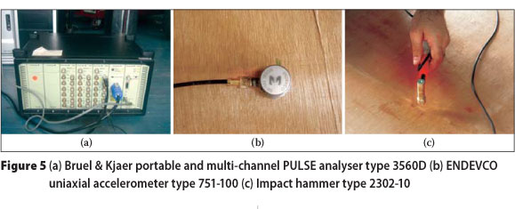
The excitation and response signals of the studied systems were recorded and measured. Bruel & Kjaer portable, and multi-channel PULSE analyser type 3560D ENDEVCO accelerometers type 751-100, and impact hammer type 2302-10 were used as the measuring devices (Figure 5), as well as the Bruel & Kjaer Pulse LabShop as measurement software. Damping ratios of the systems were also outcomes of these tests.
STRUCTURAL MODEL
The structural model of the samples is depicted in Figure 6.
According to Murray et al (1997), the dynamic modulus of elasticity for steel can be chosen similar to its static value (BS 5950 Part 4:1994), i.e. 210 GPa. Stalnaker & Harris (1999) stated that plywood is nearly isotropic because of its manufacturing process. Also, Ahmed (1999) declared that, although dry boards may be found to be isotropic or orthotropic by nature, they can easily be modelled as isotropic plates with very good results. Based on the study carried out by Narayanamurti et al in Hu (2008), Matsumoto & Tsutsumi (1968), and Bos & Bos Casagrande (2003), the dynamic Young's modulus of plywood was found to be higher than its static value. In this study, the static modulus of elasticity of plywood, available in the local market, is adopted as 7 164 MPa (Yean 2006), considering an isotropic sheeting, while the dynamic value is chosen 10% greater than the static value according to Bos & Bos Casagrande (2003).
The density of Peva45 and plywood has been chosen as 7 850 kg/m3 and 600 kg/m3 respectively.
In the PSSDB system, the stiffness of the screws which is obtained by experimental push-out tests (Ahmed 1999; Akhand 2001; Nordin et al 2009) is directly used as input data for the FEMs (Nordin et al 2009). A study was performed to identify the connection stiffness between Peva45-Cemboard, Cemboard-Timber, and Peva45-Plywood by push-out tests. Also, the shear connection stiffness between Peva45 and plywood for the same configuration was found to be 610 N/mm (Nordin et al 2009), which is the same as in this paper.
COMPUTATIONAL MODEL
To cover the second goal of this paper, three FEMs were developed to obtain natural frequencies of the PSSDB100, PSSDB200, and PSSDB300 systems. The FEMs are implemented using ANSYS finite element computer program (ANSYS 2007).
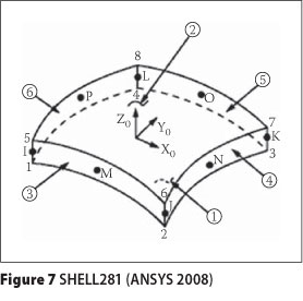
Two methods were used to evaluate the natural frequencies of the systems. The "Block Lanczos" and "QR damped" methods were utilised to extract undamped and damped natural frequencies of panels respectively. In the FEMs, the PSS and DB were assigned by element of SHELL281 (Figure 7) as it is suitable for analysing thin to moderately thick shell structures (ANSYS 2007). It comprises an 8-noded element having six degrees of freedom at each node: translation in and rotation about the x-, y- and z-axes. In addition, the screws were represented by an element of COMBIN14 (Figure 8) as the connection between Peva45 and plywood. COMBIN14 possesses longitudinal or torsional capability in 1-D, 2-D or 3-D applications (ANSYS 2007).
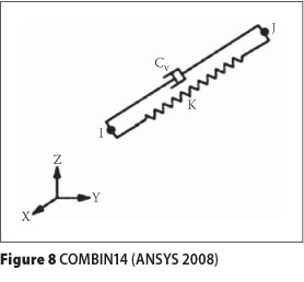
The longitudinal spring-damper option is a uniaxial tension-compression element having up to three degrees of freedom at each node: translation in the nodal x-, y- and z-directions. No bending or torsion is considered. The spring-damper element has no mass. Mass can be added by using the appropriate mass element. The spring or the damping capability may be removed from the element (ANSYS 2007). In this paper, the capability of damping was removed (Cv = 0) from the element.
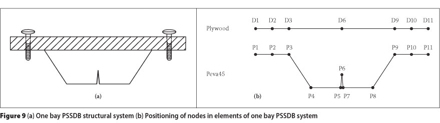
Figure 9 illustrates the procedure of modelling Peva45 and plywood in a simulation for one bay of the studied system. The connection between elements of Peva45 and plywood in the simulation is performed by using spring element (COMBIN14) in three directions (X, Y, and Z). In this case, and according to Figure 9, the nodes D2 and D10 were respectively connected to the nodes P2 and P10 in which stiffness of springs were adopted as 610 N/mm (Nordin et al 2009) in X and Y directions, and as 105 N/mm in Z (vertical) direction (see Figure 9).
OBSERVATION OF RESULTS AND COMPARISON
Results are presented in two parts - experimental and finite element simulation. Then the experimental and finite element results are compared to present the accuracy of the FEMs.
Experimental results
The FRFs of studied systems are shown in Figure 10 and according to the figure the first six natural frequencies (NFs) of the systems are presented in Table 2. Damping ratios (DRs) corresponding to the NFs of the systems are also summarised in Table 2.
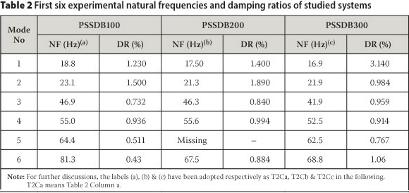
The status of the natural frequency in Table 2 was missing for the mode number 5 while the natural frequency of this mode was available in its FEM (Table 3). The reason for this absence has been revealed by evaluation of its mode shape. This mode was in the transverse direction of accelerations that were measured. Therefore, the mode did not appear in the experiments.
According to earlier studies, the PSSDB100 is stiffer than PSSDB200, and the latter is stiffer than PSSDB300 due to the number of screws. On the other hand, the mass of the PSSDB100, PSSDB200 and PSSDB300 is almost the same. As a result it can be predicted that the FNF of the PSSDB100 should be greater than that of PSSDB200, and the latter greater than that of PSSDB300. This issue was verified by results of the experimental test. Table 2 shows that the partial interaction between two main elements of the PSSDB system had an effect on the natural frequencies of the systems, as the FNF of the system increased by 3.55% and 11.24% respectively for changing the screw spacing from 300 mm to 200 mm, and 300 mm to 100 mm. However, reduction of the screw spacing decreases the damping of the system. The FNFs of the studied panels were measured by the test well above 10 Hz. Therefore all panels fell in the HFF category (Middleton & Brownjohn 2010) and were also comfortable for users (Wright et al 1989).
Finite element results
The experimentally observed FRFs of the systems presented their damped natural frequencies. Therefore, in the simulation, damped natural frequencies of the systems were determined by the QR damped method via the ANSYS finite element package. In the QR damped method, damping of the system is introduced by the Rayleigh damping approach (see more detail in Clough & Penzien 1993). According to Chowhury & Dasgupta (2003), only the first few modes of a structure with large degrees of freedom (around three at minimum and about 25 at maximum) contribute to the dynamic response of a structure. In this study, the first six modes are assumed to be significant in the dynamic behaviour of the system. Then the Rayleigh damping coefficients were determined (Chowhury & Dasgupta 2003) and used in the simulation.
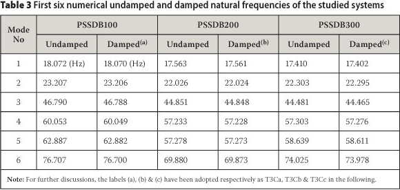
Three finite element models were developed to identify the natural frequencies of the PSSDB100, PSSDB200 and PSSDB300 systems. The first six undamped and damped natural frequencies of the studied systems are summarised in Table 3.
According to simulation results, the FNF of the PSSDB100 was greater than the PSSDB200, and the latter was greater than PSSDB300. This point is also confirmed by the experimental results. Table 3 shows small differences between undamped and damped natural frequencies of the systems. The results also show that the undamped natural frequencies of all systems were greater than their corresponding damped natural frequencies. Caughey & O'Kelly (1961) stated that, in a system with classical normal modes, the damped natural frequencies are always less than or equal to their corresponding undamped natural frequencies. Piersol et al (2010) mentioned that generally classical normal modes exist in a structure without damping or with particular types of damping. According to the results of this study, the measured damping can be considered as particular damping for each system; therefore they can be used in the dynamic analysis of the bare PSSDB systems with different screw spacing.
Comparison of experimental and finite element results
As stated, the FRFs of the systems present their damped natural frequencies. However, undamped and damped natural frequencies of the studied systems were calculated very close to one another by the numerical method. Nevertheless, damped natural frequencies of the systems which were determined by FEM are compared with their damped natural frequencies that have been evaluated by the tests in order to reveal more accurate errors. The errors of numerical results are calculated by Eq (1) and presented in Table 4.
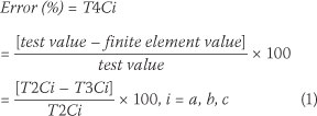
where:
T2Ci: column i = a, b, c of Table 2
T3Ci: column i = a, b, c of Table 3
T4Ci: column i = a, b, c of Table 4
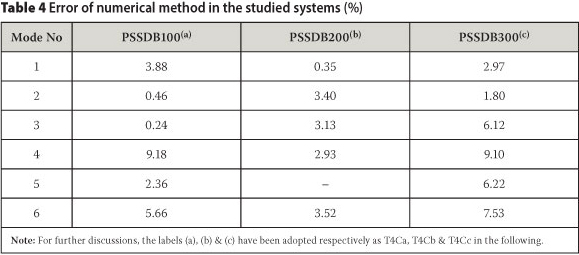
The mentioned errors show that the FEMs can predict the natural frequencies of the PSSDB system with accuracy. Therefore, performed convergence studies on the finite element models and selected elements of the models which were combinations of the SHELL281 and COMBIN14 elements were suitable for the purpose of the study. The difference between the experimental and FEM results may be due to reasons such as:
■ Finite element method is a numerical approximate method.
■ Imperfections of the PSS, DB and screws in the test specimens were not captured in the FEMs.
PARAMETRIC STUDY
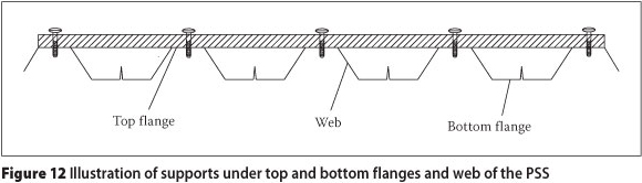
A series of parametric studies based on the FEMs for the PSSDB200 system were performed to show the effect of different conditions on the FNF of the system. The PSSDB system with a length of 2 400 mm and a width of 795 mm was chosen as the control sample, adopting 0.8 mm thick Peva45 as PSS, 18 mm thick plywood as DB, DS-FH 432 self-drilling and self-tapping screws at 200 mm screw spacing as the connectors, and pin support at Y = 0 and roller support at Y = 2 400 mm both at the bottom flange of the PSS (Figure 6(a)). A series of studies were performed to uncover the FNF of the PSSDB panels with practical dimensions. Their categorisation and level of comfort were also revealed. All supports in these studies were considered at the bottom flange of the PSS. Only in one case supports were assumed at the bottom, top and web of the PSS (see Figure 12).
Effect of thicknesses of Peva45 and plywood
The thickness of the considered Peva45 is 0.8 mm and 1.0 mm, whilst the thickness of the plywood is 9.252, 12.7, 18, 23 and 25 mm. Both products are available on the local market. The effect of the thicknesses of Peva45 and plywood on the FNF of the system is presented in Table 5. The percentage difference between the FNF of the control sample and the FNF of the panel with other thicknesses for Peva45 and plywood are also presented in Table 5.
According to the results, increasing the thicknesses of the Peva45 and the plywood enhanced and decreased the FNF of the system respectively. By enhancing the thickness of the Peva45 from 0.8 mm to 1.0 mm, and the thickness of the plywood from 9.252 mm to 25 mm the FNF increased and decreased by an average value of 4.91% and 18.56% respectively. It can therefore be seen that the obtained results are a manifestation of the effect of the mass and stiffness of Peva45 and plywood on the FNF of the system. The highest value of the FNF occurred for the maximum thickness of Peva45 and minimum thickness of plywood (20.677 Hz), whilst the lowest value of the FNF occurred for the minimum thickness of Peva45 and maximum thickness of plywood (16.566 Hz).
Therefore, by changing the thickness of main elements the FNF can be increased by a maximum value of 24.82%. The minimum value of the FNF of the studied system showed well above 10 Hz. The studied system was therefore in the HFF category and also comfortable for occupants.
Effect of boundary conditions
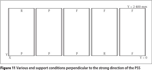
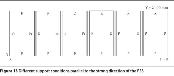
The effect of boundary conditions on the FNF of the system was taken into account in three situations: effect of sliding and rotation at the end supports perpendicular to the strong direction of the PSS (sliding parallel with Y direction of the plan, Figure 11); effect of locating support under the top flange and web of the PSS at two ends of the length (Figure 12); and effect of adding support parallel with the strong direction of the PSS (parallel with Y direction of the plan, Figure 13).
Effect of sliding and rotation of supports
The effect of sliding and rotation at the end supports perpendicular to the strong direction of the PSS (X direction, Figure 11) on the FNF of the system is investigated for various support conditions, as shown in Figure 11. These involve (i) pin (P) and roller (R) (control sample), (ii) P-P, (iii) P-F (fixed), (iv) R-F and (v) F-F end supports.
The FNF results for these conditions are presented in Table 6. The percentages of the increase (PI) in the FNF of the various models over the control sample are also shown in Table 6.
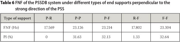
The results show that if sliding is constrained parallel with the strong direction of the PSS (P-R support converted into P-P support), then the FNF is increased significantly. Chao & Chern (2000) and Jalali (2012) affirmed this observation. On the other hand, changing a pin support to a fixed support (P-F instead of P-P, and F-F instead of P-P) did not show a considerable effect on the FNF value. Therefore, the control of rotation at the bottom flange of the PSS at the end support did not significantly affect the FNF of the system.
Effect of adding support under top flange and web of PSS
The supports for the control sample were only considered under the bottom flange (Case 1) of the PSS. Table 7 shows the FNF and PI in the FNF for various models over the control sample of the system if additional supports are provided at both the top and bottom flanges of the PSS (Case 2), and at the top and bottom flanges and the web (Figure 12) of the PSS (Case 3).

When comparing the results of Cases 1 and 2, it is clear that the FNF of the system is enhanced significantly if supports are added at the top and bottom flanges of the PSS. Also, by comparing the results of Cases 2 and 3, it is demonstrated that additional supports at the web do not have any significant effects on the FNF of the system. This may be because adding support on the top flange already prevents rotation of the PSS, so adding more support on the web does not make a big difference. By keeping the above-mentioned three cases in mind, designers can decide on the shape of supports (beams) which can be used under the PSS of the PSSDB floor system to reduce its natural frequencies.
Effect of adding support parallel with longitudinal side edges
The supports of the longitudinal side edges (support in X = 0 and 795 mm parallel with Y direction of the plan as in Figures 6(b) and 13) for the control sample were considered free (unconstrained). Various additional support conditions studied at the longitudinal side edges are shown in Figure 13. Table 8 shows the FNF and PI in the FNF for various models in the control sample.
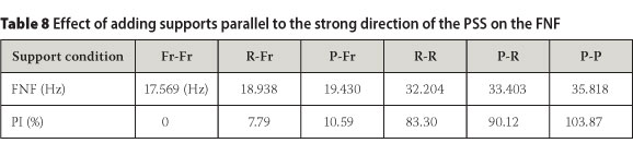
As shown in Table 8, when only one of the longitudinal side edges was supported one side edge free), as in the R-Fr and P-Fr cases, the FNF increased slightly. It can be seen that restraining sliding perpendicular to the strong direction of the PSS (X direction of the plan) would not change the FNF of the system much (2.8% = 10.59%-7.79%) if only one of the longitudinal side edges were supported. However, the increase in FNF was much more significant, based on restraining both longitudinal side edges as in the R-R, P-R and P-P cases. The control of sliding perpendicular to the strong direction of the PSS shows a pronounced effect on increasing the FNF of the system (20.57% = 103.87%-83.30%), where both longitudinal side edges of the panel were supported (P-P instead of R-R).
FNF of panels with practical dimensions
Peva45 is available on the local market in widths of 795 mm and maximum lengths of 15 m. Also, the maximum length and width of plywood is 2 400 mm and 1 200 mm respectively. Therefore, to prepare bigger practical panels, some pieces of Peva45 and plywood should be used together. Fifteen panels in four different lengths of 1 200 mm, 2 400 mm, 3 600 mm and 4 800 mm involving one, two, three and four repeating sections of the system were developed, which were combinations of elements similar to the control sample, verified by experiments, as shown in Figure 6(b) and Figures 14-16. In all fifteen panels, the length and width of all pieces of plywood were chosen as 2 400 mm and 795 mm respectively. Also, the length of Peva45 was used as the length of the panels.
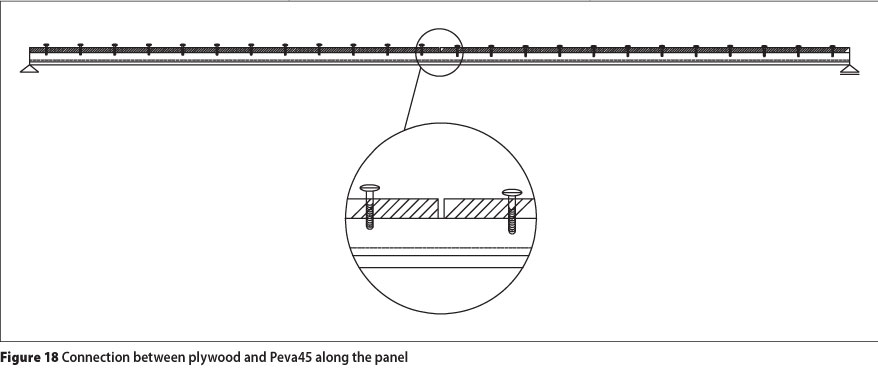
The connection between two adjacent side-by-side panels (detail A) was represented by a typical lap joint idea as shown in Figure 17. Wright & Evans (1987) presented the connectivity characteristics of such a joint. As can be seen in Figure 17, nodes i(2) and j(2) are connected to node i(3) and node j(3) respectively, assuming complete freedom in the longitudinal and rotational directions, whilst assumed to have complete connection in the vertical and lateral directions (Wright & Evans 1987). It should be noted that connections between i(1) and j(1) respectively to i(2) and j(2) (Peva45 to plywood) are represented by results of the study by Nordin et al (2009).
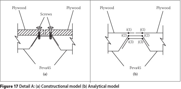
The joint does not exist perpendicularly to the strong direction. Figure 18 shows the connection between plywood and Peva45 according to their dimensions.
Table 9 shows the characteristics and the FNF of the developed panels with practical dimensions. The categorisation (LFF or HFF) and level of comfort of the panels are also undertaken. All panels had pin-roller supports perpendicular to the strong direction of the PSS and free-free supports parallel with the strong direction of the PSS (Model 0).
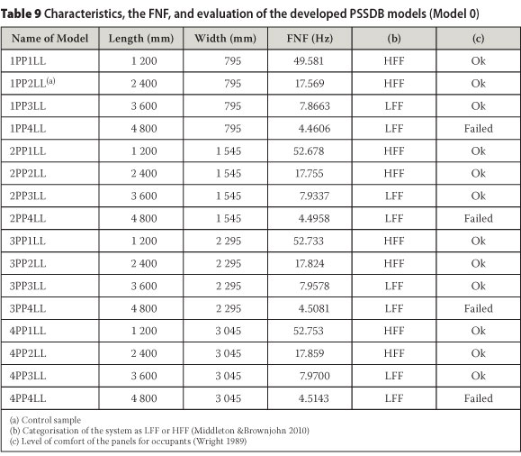
The width of the panels with only end supports perpendicular to the strong direction of the PSS did not significantly affect the FNF of the system, as the panels with the same length and widths of 795 mm, 1 545 mm, 2 295 mm and 3 045 mm had close values in terms of the FNF. The reason for this was the enhancement of the stiffness and mass by increasing the width. However, the FNF of the 3 045 mm wide panel was a bit greater than the FRF of the 2 295 mm wide panel, etc. This may be due to the increased stiffness of the panels when using lap joints in the panels, with two pieces of Peva45 (one-lap joint), three pieces of Peva45 (two-lap joints), and four pieces of Peva45 (three-lap joints), compared to panels with one piece of Peva45 without a lap joint (795 mm wide).
It is obvious that the length of the system has a direct effect on the FNF of the system. The results showed that the FNF of a PSSDB system with a length of more than 3 600 mm and widths of 795 mm, 1 545 mm, 2 295 mm and 3 045 mm fell in the LFF category. Also, panels that were 3 600 mm and 4 800 mm long, with any widths, were respectively shown to be comfortable and uncomfortable for users.
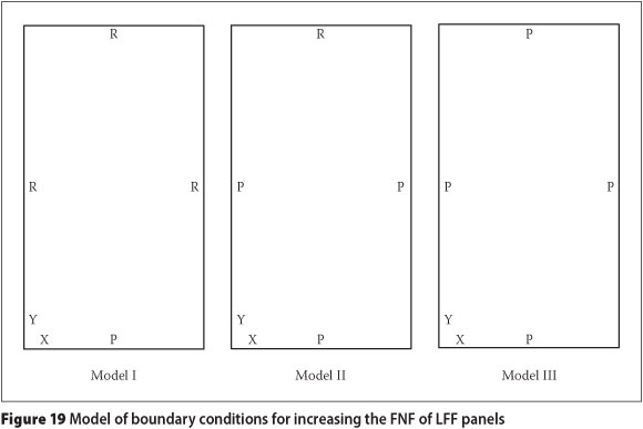
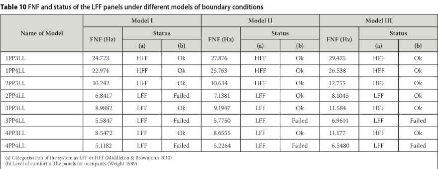
An increase in the FNF of a floor system (less resonance) is required for user comfort. If panels are supported on all sides, the FNF of the system will be higher. This can be used to increase the FNF (stiffness) of the panels via boundary conditions. Depending on the control of sliding at supports, roller or pin supports can be used on all sides. In this case, all panels with lengths of 3 600 mm and 4 800 mm were selected in order to increase their FNFs through three boundary conditions as shown in Figure 19. Table 10 summarises the increased FNFs of the panels corresponding to these boundary conditions (models I, II, and III). It also illustrates the level of comfort of the studied panels.
The PI in the FNF of the selected panels are listed in Table 11 by comparing the FNFs of the panels under boundary conditions of models I, II, and III with the FNFs of the panels under boundary conditions of model 0.
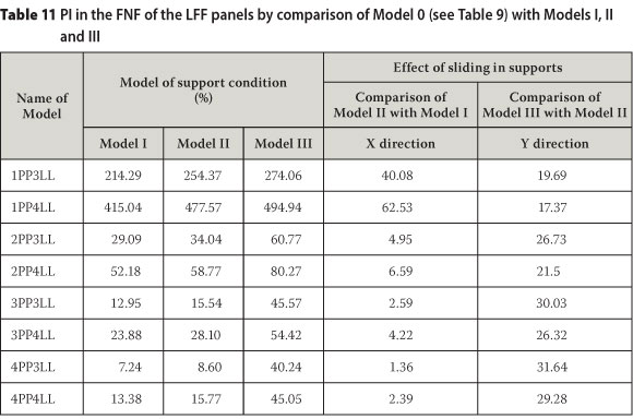
Table 11 shows that control of sliding parallel with the strong direction of the PSS in the multi-panel systems had a significant effect on the FNF of the system. However, control of sliding perpendicular to the strong direction of the PSS considerably affected the FNF of the 795 mm wide panel and did not have a significant effect on the FNF of the panels wider than 795 mm. Even by using the model III boundary condition (pin supports in all sides), the panels that were 4 800 mm long, with widths of 1 545 mm, 2 295 mm and 3 045 mm were still in the category of LFF. Also, panels with a length of 4 800 mm and widths of 2 295 mm and 3 045 mm were not comfortable for users.
CONCLUSIONS
This paper reveals experimentally and numerically the natural frequencies of the PSSDB system, considering the effect of the level of interaction between the PSS and the DB. It is shown that the PSSDB system with lower screw spacing has higher FNF. The damping ratio of the PSSDB system is inversely related to the stiffness of the system, as the damping ratio of the PSSDB with lower screw spacing is greater than the system with higher screw spacing. A series of parametric studies reveal the effects of different parameters on the FNF of the system. It is proved that the FNF of the PSSDB system is significantly influenced by (i) screw spacing or level of interaction between the PSS and DB, (ii) thicknesses of the PSS and DB, (iii) control of sliding along the strong direction of the PSS, (iv) using support under both the top and bottom flanges of the PSS, and (v) the number of side edges being supported. On the other hand, the FNFs are not much affected by (i) control of sliding along the weak direction of the PSS at the side edge supports, (ii) rotations at all end and side edge supports, and (iii) the support conditions under the web of the PSS. Identification of the FNF of the panels with practical dimensions with end supports only shows that the FNF of the panels with the same length and different widths are very close to one another. However, a small difference may occur by increasing the thickness of Peva45 in the location of the lap joint. It is proved that a significant increase in the FNF of the PSSDB floor system with practical dimensions is possible via boundary conditions.
ACKNOWLEDGEMENTS
The authors would like to acknowledge the Mechanical Engineering Department of Universiti Kebangsaan Malaysia for granting permission to conduct the experimental tests. The authors also express their gratitude to Mr Alireza Bahrami and Dr Mohammad Hosseini Fouladi for their contributions to some parts of this study.
REFERENCES
Ahmed, E, Wan Badaruzzaman, W H & Khalim, A R 1996. A simplified elastic composite floor section analysis with incomplete interaction. Jurnal Kejuruteraa, 8: 67-78. [ Links ]
Ahmed, E 1999. Behavior of profiled steel sheet dry board folded plate structures. PhD Thesis, Malaysia: Universiti Kebangsaan, Department of Civil & Structural Engineering. [ Links ]
Ahmed, E, Wan Badaruzzaman, W H & Wright, H D 2000. Experimental and finite element study of profiled steel sheet dry board folded plate structures. Thin-Walled Structures, 38: 125-143. [ Links ]
Ahmed, E & Wan Badaruzzaman, W H 2006. Bondok II/cemboard composite floor panel: Development, structural performances and applications. Proceedings, The Earth East Asia-Pacific Conferences on Structural Engineering and Construction, Bangkok, Thailand, 591-596. [ Links ]
Akhand, A M 2001. Nonlinear finite element modeling and partial plastic analysis of composite profiled steel sheeting dry board continuous floor. PhD Thesis, Malaysia: Universiti Kebangsaan, Department of Civil & Structural Engineering. [ Links ]
ANSYS Version 11.0 2007. Swanson Analysis Systems, Inc., Houston, PA, US. [ Links ]
Bayat, B, Pakar, I & Bayat, M 2011. Analytical study on the vibration frequencies of tapered beams. Latin American Journal of Solids and Structures, 8(2): 149-162. [ Links ]
Bos, F & Bos Casagrande, S 2003. On-line non-destructive evaluation and control of wood-based panels by vibration analysis. Journal of Sound and Vibration, 268: 403-412. [ Links ]
BS 5950 1994. Structural use of steelwork in building. Part 4: Code of practice for design of composite slabs with profiled steel sheeting. British Standards Institution, UK. [ Links ]
Caughey, T K & O'Kelly, M E J 1961. Effect of damping on the natural frequencies of linear dynamic systems. The Journal of the Acoustical Society of America, 33(11): 1458-1461. [ Links ]
Chao, C C & Chern, Y-Ch 2000. Comparison of natural frequencies of laminates by 3-D theory. Part I: Rectangular plates. Journal of Sound and Vibration, 230(5): 985-1007. [ Links ]
Chowdhury, I & Dasgupta, S P 2003. Computation of Rayleigh damping coefficients for large systems. The Electronic Journal of Geotechnical Engineering, 8: Bundle 8C. [ Links ]
Clough, R W & Penzien, J 1993. Dynamics of structures, 2nd edition, New York: McGraw-Hill. Da Silva, J G S, Da Silva Vellasco, P C G, De Andrade, S A L & De Lima, L R O 2006. Dynamical response of composite steel deck floors. Latin American Journal of Solids and Structures, 3(2): 163-178. [ Links ]
De A Mello, A V, Da Silva, J G S, Da Silva Vellasco, P C G, De Andrade, S A L & De Lima, L R O 2008. Modal analysis of orthotropic composite floors slabs with profiled steel decks. Latin American Journal of Solids and Structures, 5(1): 47-73. [ Links ]
De Silva S S & Thambiratnam D P 2009. Dynamic characteristics of steel-deck composite floors under human-induced loads. Computers and Structures, 87: 1067-1076. [ Links ]
Ebrahimpour, A & Sack, R L 2005. A review of vibration serviceability criteria for floor structures. Computers and Structures, 83: 2488-2494. [ Links ] El-Dardiry, E, Wahyuni, E, Ji, T & Ellis, B R 2002. [ Links ]
Improving FE models of a long-span flat concrete floor using natural frequency measurements. Computers and Structures, 80: 2145-2156. [ Links ] Ellingwood, B & Tallin, A 1984. Structural serviceability floor vibrations. Journal of Structural Engineering, 110: 401-420. [ Links ]
Ferreira, A J M & Fasshauer, G E 2007. Analysis of natural frequencies of composite plates by an RBF-pseudospectral method. Composite Structures, 79: 202-210. [ Links ]
Filiatrault, A, Folz, B & Foschi, R O 1990. Finite-strip free-vibration analysis of wood floors. Journal of Structural Engineering, 116(8): 2127-2142. [ Links ]
Fukuwa, N, Nishizaka, R, Yagi, S, Tanaka, K & Tamura, Y 1996. Field measurement of damping and natural frequency of an actual steel-framed building over a wide range of amplitudes. Journal of Wind Engineering and Industrial Aerodynamics, 59: 325-347. [ Links ]
Gandomkar, F A, Wan Badaruzzaman, W H & Osman, S A 2011. The natural frequencies of composite Profiled Steel Sheet Dry Board with Concrete infill (PSSDBC) system. Latin American Journal of Solids and Structures, 8: 351-372. [ Links ]
Honda, S & Narita, Y 2012. Natural frequencies and vibration modes of laminated composite plates reinforced with arbitrary curvilinear fiber shape paths. Journal of Sound and Vibration, 331(1): 180-191. [ Links ]
Hu, Y 2008. Nondestructive testing of mechanical parameters for wood-based materials. Proceedings, 17th World Conference on Nondestructive Testing, Shanghai, China. [ Links ]
Hurst, H T & Lezotte, H R 1970.A comparison of vibrational characteristics of wooden floor constructions. Build Science, 5: 105-109. [ Links ]
Jalali, A 2012. Dynamic analysis of isotropic and laminated reinforced composite plates subjected to flowing fluid. Master's Dissertation, Montreal, Canada: University of Montreal, Department of Mechanical Engineering. [ Links ]
Ju, Y K, Kim, D Y, Kim, S D, Yoon, S W, Lee, Y K & Kim, D H 2008. Dynamic characteristics of the new composite floor system. Steel Structures, 8: 347-356. [ Links ]
Ljunggren, F, Wang, J & Agren, A 2007. Human vibration perception from single- and dual-frequency components. Journal of Sound and Vibration, 300: 13-24. [ Links ]
Matsumoto, T & Tsutsumi, J 1968. Elastic properties of plywood in dynamic test. I. Relation between static Young's Modulus and dynamic Young's Modulus. Mokuzai Gakkaishi, 14(2): 65-69. [ Links ]
Middleton, C J & Brownjohn, J W W 2010. Response of high frequency floors: A literature review. Engineering Structures, 32(2): 337-352. [ Links ]
Murray, M M, Allen, D E & Ungar, E E 1997. Floor vibration due to human activity. AISC: 11th Steel Design Guide Series, Chicago, US. [ Links ]
Murray, T M 1981. Acceptability criterion for occupant-induced floor vibrations. Engineering Journal: American Institute of Steel Construction, 18(Q2): 62-70. [ Links ]
Nordin, N, Wan Badaruzzaman, W H & Awang, H 2009. Connector stiffness of 'Peva-Cemboard' screwed connection in Profiled Steel Sheet Dry Board (PSSDB) panel. Proceedings, 5th International Conference on Construction in the 21st Century (CITC-V), "Collaboration and Integration in Engineering Management and Technology", Istanbul, Turkey, 1476-1482. [ Links ]
Piersol, A G, Harris, C M & Paez, T L 2010. Harris's shock and vibration handbook, 6th edition. New York: McGraw-Hill. [ Links ]
Soedel, W 2004. Vibrations of shells and plates. New York: Marcel Dekker. [ Links ] Stalnaker, J J & Harris, C E 1999. Structural design in wood. Massachusetts, US: Kluwer Academic. [ Links ]
Velmurugan, R 2011. Modal analysis of pre- and post-impacted nanocomposite laminates. Latin American Journal of Solids and Structures, 8(1): 9-26. [ Links ]
Wan Badaruzzaman, W H & Wright, H D 1998. Lightweight thin-walled Profiled Steel Sheeting/Dry Board (PSSDB) composite floor system. Proceedings, 2nd International Conference on Thin-walled Structures: Research and Development, 355-365. [ Links ]
Wan Badaruzzaman, W H, Zain, M F M, Akhand, A M & Ahmed, E 2003. Dry board as load-bearing element in the Profiled Steel Sheet Dry Board floor panel system - Structural performance and applications. Journal of Construction and Building Materials, 17(4): 289-297. [ Links ]
Wiss, J F & Parmelee, R A 1974. Human perception of transient vibrations. Journal of the Structural Division, 100(ST4): 773-787. [ Links ]
Wright, H D & Evans, H R 1987. A folded plate method of analysis for profiled steel sheeting in composite floor construction. Thin-Walled Structures, 5: 21-37. [ Links ]
Wright, H D, Evans, H R & Burt, C A 1989. Profiled steel sheet/dry boarding composite floors. Thez Structural Engineer, 67: 114-121. [ Links ] Xing, Y F & Liu, B 2009. New exact solutions for free vibrations of thin orthotropic rectangular plates. Composite Structures, 89: 567-574. [ Links ]
Yean, T C 2006. Load-carrying capacity of dry floor panel system. MSc Dissertation, Malaysia: Universiti Teknologi Malaysia, Faculty of Civil Engineering. [ Links ]
 Contact details:
Dr Farhad Abbas Gandomkar
Department of Civil & Structural Engineering
Faculty of Engineering & Built Environment
Universiti Kebangsaan Malaysia
43600 Bangi, Selangor, Malaysia
T: 00603 8925 5760/1492
F: 00603 8925 5703,
E: farhad.abbas.gandomkar@gmail.com
Contact details:
Prof Wan Hamidon Wan Badaruzzaman
Department of Civil & Structural Engineering
Faculty of Engineering & Built Environment
Universiti Kebangsaan Malaysia
43600 Bangi, Selangor, Malaysia
T: 00603 8925 5760/1492
F: 00603 8925 5703
E: whamidon@vlsi.eng.ukm.my
Contact details:
Prof Siti Aminah Osman
Department of Civil & Structural Engineering
Faculty of Engineering & Built Environment
Universiti Kebangsaan Malaysia
43600 Bangi, Selangor, Malaysia
T: 00603 8921 6221
F: 00603 8921 6147
E: saminah@eng.ukm.my
Contact details:
Prof Amiruddin Ismail
Department of Civil & Structural Engineering
Faculty of Engineering & Built Environment
Universiti Kebangsaan Malaysia
43600 Bangi, Selangor, Malaysia
T: 00603 8921 6203
F: 00603 8921 6147
E: abim@eng.ukm.my

DR FARHAD ABBAS GANDOMKAR obtained his BEng in Civil Engineering from Shahid Chamran University of Ahvaz in 1996, his MSc in Structural Engineering from Isfahan University of Technology in 1999, and his PhD in Structural Engineering from Universiti Kebangsaan Malaysia in 2012. He has been a full-time ecturer at the Ahvaz branch of the Islamic Azac University, Iran, since 1999 and is a member of the Khouzestan Construction Engineering Disciplinary Organization. He has more than 13 years' experience n teaching, training, research, publication and administration.

PROF WAN HAMIDON WAN BADARUZZAMAN obtained his PhD in Structural Engineering from the University of Wales, Cardiff, UK in 1994. He is Professor of Structural Engineering at the National University of Malaysia, where he began his career almost 30 years ago. His research interest focuses on the profiled stee sheeting dry board (PSSDB) system, a lightweight composite structural system that he has developed over the years. He has published many papers related to research findings on this patented and award-winning construction system.

PROF SITI AMINAH OSMAN is Associate Professor in Civil and Structural Engineering, and is a member of the Board of Engineers Malaysia. She graduated from Universiti Teknologi Malaysia in 1992 with a BEng (Hons), MSc in Structural Engineering from the University of Bradford, UK (1995) and a PhD in Civi and Structural Engineering from Universit Kebangsaan Malaysia (2006). After her undergraduate studies, she started ecturing at Universiti Kebagsaan Malaysia. Her interests are structura engineering, wind engineering and industrial building system construction.

PROF AMIRUDDIN ISMAIL obtained his BEng in CM Engineering from the University of Pittsburgh, USA, in 1983, his MSc in Transportation and Urban Systems from the University of Pittsburgh in 1984, and his PhD in Transportation Engineering from Universiti Kebangsaan Malaysia in 2002. He is currently Professor in Civil & Structural Engineering at Universiti Kebangsaan Malaysia, and has more than 25 years' experience in teaching, training, research, publication and administration.

