


Services on Demand
Article
 English (pdf)
 Article in xml format
 Article references
Indicators

Related links
-
 Cited by Google
 -
 Similars in Google
Share

 Permalink
Journal of the South African Institution of Civil Engineering
On-line version ISSN 2309-8775
Print version ISSN 1021-2019
J. S. Afr. Inst. Civ. Eng. vol.54 n.2 Midrand Jan. 2012
TECHNICAL PAPER
Prediction of the debonding/ slip load of composite deck slabs using fracture mechanics
J Mahachi; M Dundu
ABSTRACT
The aim of this paper is to develop equations that can be used to predict the load at which debonding or slip occurs in composite deck slabs, failing as a result of shear bond rupture. Debonding is the separation of the bonded steel plate from the concrete. The expressions are based on end-slip of the shear span occurring prior to ultimate load. Shear bond failure is considered to be a result of breakdown of mechanical and frictional resistance force between the steel and the concrete interface. Linear elastic fracture mechanics (LEFM) is assumed and the eccentric axial force transmitted by the steel deck is calculated using rotational congruence. The theoretical debonding load results are found to be comparable with experimental results, and to be of use in formulating the response of composite slabs when subjected to fatigue load.
Keywords: composite decks, debonding, shear bond failure, linear elastic fracture mechanics, fatigue
INTRODUCTION
Composite steel deck floor slabs consist of concrete cast on top of cold-formed profiled steel sheets (Krige & Mahachi 1995). The steel deck is made by cold-forming structural grade sheet steel into a repeating pattern of parallel ribs, and the concrete, which may be either lightweight or normal weight, is then poured onto the decking, usually by pumping, to make up the composite system. Metal decking acts both as permanent formwork for the concrete, eliminating the need to provide props, and as tensile reinforcement for the slab. The integral composite action between the steel deck and the concrete is provided by mechanical interlocking devices (embossments) capable of resisting horizontal shear and preventing vertical separation of the steel/concrete interface. This form of slab construction is particularly popular for multi-storey buildings and bridge construction, when rapid construction is required.
Tests carried out by a number of researchers (Ekberg & Schuster 1968; Schuster & Ekberg 1970; Luttrell & Davison 1973; Porter & Ekberg 1976; Wright et al 1987; Mahachi 1997) have shown that generally the two materials exhibit complete interaction at relatively low loads. The load vs vertical mid-span deflection is linear up to the point when loss of interaction between the two materials occurs. The loss of interaction has been attributed to loss in shear bond. Determination of the debonding load is important, since it has been observed in fatigue tests (Mahachi 1994, 1995) that subjecting composite slabs to fatigue loads above the debonding load generally results in shear bond rupture. The debonding load is also important for serviceability, since deflection of the slab should be such that slippage does not occur at working loads. This paper will focus on the development of the debonding load for two steel deck profiles manufactured in South Africa, i.e. the Bond-Lok and the Bond-Dek.
The Bond-Lok and Bond-Dek floor slabs are one-way spanning slabs and are designed to carry uniformly distributed loads. They provide permanent formwork/shuttering to the wet concrete floor with an attractive flat ceiling on the underside and are able to span up to 3 m, unsupported, thus saving on the props utilised. The Bond-Lok decks have plain cold-rolled profiled steel sheets with male and female ribs that interlock. The deck has some form of re-entrant or dove tail angle, which prohibits vertical separation of concrete and steel deck due to the interlocking shape. When used with concrete, the system forms a composite slab, with the ribs bonded to the slab. A chemical bond is also formed with the ribs and flat section of the unit. The Bond-Lok tested in this investigation had a cover of 320 mm, gauge thickness of 0.92 mm and a trough depth of 50 mm (Figure 1(a)). To prevent rusting, galvanised surface coating with an average thickness of 0.035 mm (Z275) was bonded on both surfaces of the metal deck.
The steel deck profile for the Bond-Dek is trapezoidal in cross-section, as shown Figure 1(b). This figure also shows the dimensions of the Bond-Dek specimen that was tested. Both surfaces of the profile were galvanised with a 0.015 coating to prevent rusting. The shear connection in Bond-Dek is more reliable than that of the Bond-Lok, because of the embossments that project from the corrugations. The embossments run across the webs and provide good mechanical shear connection. The profile of the Bond-Dek is further stiffened by longitudinal grooves that run along the steel deck flanges to reduce the effects of buckling during construction loading. Both composite systems have been fire-tested by the Council of Scientific and Industrial Research (CSlR) in South Africa and have qualified for a rating of two hours. For normal applications of Bond-Dek steel floors, no additional reinforcing other than a light mesh for shrinkage control is required, typically 193 mesh.
ANALYSIS
The behaviour and strength of composite slabs are often governed by the horizontal shear load at the interface of the steel deck and the concrete. Shear connection between steel and concrete is normally achieved by chemical adhesion, frictional resistance and mechanical interlock, collectively. The bond thus attained depends on panel geometry, thickness of the steel sheeting and concrete, surface conditions of the steel deck and types of embossments or rolled dimples that project from the steel deck into the concrete.
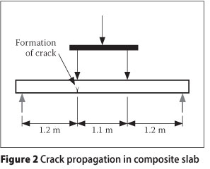
In this analysis, equations to predict the load (Pd) at which debonding occurs are developed using linear elastic fracture mechanics (LEFM). LEFM is assumed since concrete does not behave plastically under tensile situations. The horizontal slip resistance requires two experimentally determined parameters to model the interface slip, i.e. the coefficient of friction, , and the shear strength parameter, τ. The analysis is performed on a simply supported composite deck slab subjected to static point line loads. When subjected to loading, a discrete crack is assumed to form and propagate in the concrete under one of the loading points as shown in Figure 2.
The following assumptions will be made in the analysis:
1. The crack is assumed to propagate vertically upwards from the bottom.
2. Within the regime of LEFM, a linear elastic law will be assumed for concrete, and a rigid-plastic constitutive law for steel. This assumption can be considered valid since debonding normally occurs in the linear elastic regime.
3. The interface slip consists mainly of mechanical interlock and friction. The effect of the adhesion bond is assumed to be negligible.
4. Debonding of the steel/concrete interface occurs before the ultimate load.
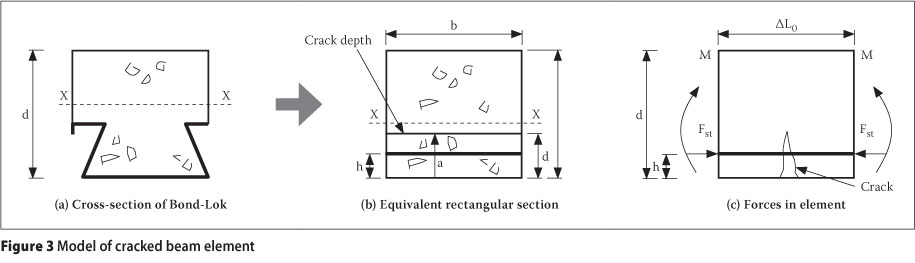
In order to calculate the rotation in a cracked element, subjected to a bending moment and/or axial force, it is proposed to use the "Compliance Approach", suggested by Okamura et al (1973, 1975) and Carpinteri (1984). For this approach to work, the composite cross-section is converted to an "equivalent" rectangular section by transforming the section so that the bending stiffness about the X-X axis remains the same, as shown in Figure 3. In the transformed section, the steel area is assumed to be concentrated at a height h from the bottom, and a crack of height a, penetrating through the thickness of the model.
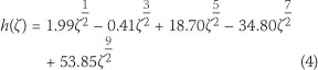
Consider a small element of the slab of length as shown in Figure 3, subjected to an opening external moment M. Under the external moment, LEFM assumes that the force transmitted to the concrete increases with increasing moment until slippage or yielding of steel occurs. Due to the influence of the moment an eccentric axial force Fst will be induced in the steel deck. The force transmitted by the steel deck to the beam can be estimated by the principle of rotational congruence. This force is expected to increase linearly as the moment increases, until debonding occurs. The stress intensity factor K1 for a rectangular section (width b and height d) that contains an edge crack of depth a, subjected to a bending moment Mx about the centroid of the section has been shown by Okamura et al (1973, 1975) to be given by:
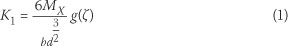
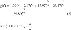
where, the function of the relative crack depth ζ is for ζ < 0.7 and IMAGEM AQUI
Similarly, the stress intensity factor K2 for a rectangular section subjected to an axial force Fx acting at the level of the steel has been shown by Okamura et al (1973, 1975) to be
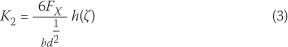
where
Whilst an uncracked section behaves as a perfectly fixed joint, a cracked section behaves as an elastic joint. Using a rotational congruence approach similar to that used by Okamura et al (1973, 1975) and Carpinteri (1981) for reinforced concrete, the rotation φ of the crack due to an applied bending moment Mx and an axial force Fx can be evaluated by the principle of linear superposition as

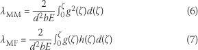
Parameters and are the compliances of the member due to the existence of the crack and can be derived from energy methods by considering the moment Mx and the axial force acting together to give
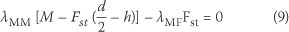
At the point of slippage the net rotation φ = 0 since the applied bending moment to open the crack and the axial force from the steel deck, to close the same crack, are of the same magnitudes. Setting φ = 0 in Eq (5) yields the angular compatibility equation:

From Figure 3, the applied bending moment Mx = M - Fst(d/2 - h) and the axial force Fx = -Fst. Substituting Mx and Fx in Eq (8) gives
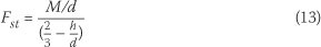
Rearranging Eq 9 gives the indeterminate force Fst as a function of the applied moment M, that is
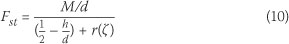
where
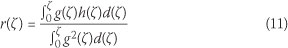
From Eq (11):

Substituting Eq (12) into Eq (10) results in
Now consider the equilibrium of horizontal forces, along the shear span as shown in Figure 4.
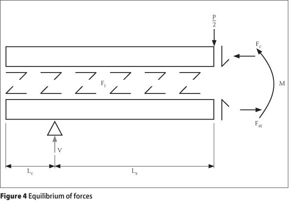
In the figure Lc is the overhang length, Ls is the shear span and Ft is the interface force. If a load P is applied to the composite system (see Figure 1), then the slab is subjected to a two-point line loading, with each point load of magnitude P/2. For horizontal equilibrium, the interface force is Fi given by

where Fc = Force in the concrete. The limiting force F1 at the interface is due to the mechanical interlock and friction (Patrick & Bridge 1990; Schuster & Ling 1990) and is given by

where V is the clamping force due the vertical reaction, At is the interface area, im is the mechanical shear strength parameter and the coefficient of friction. As long as Ft < F1 no slippage occurs. This implies that the limit force for slippage to occur is

It can be deduced from Eqs (14), (15) and (16) that debonding starts to occur when

Substituting Eq (17) into Eq (13) yields
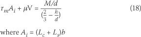
Eq (18) can be solved to obtain the maximum loads that can be applied to the slab before debonding starts to occur.
APPLICATION
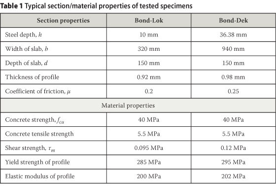
Fatigue tests were carried out by Mahachi (1997) in order to determine the response of composite Bond-Lok and Bond-Dek slabs to fatigue loading. Initial experimental tests involved the determination of the maximum ultimate static load, as well as the load at which debonding occurs. It was necessary to determine the load at which slip occurred, since applying a fatigue load above this resulted in immediate failure or a failure after a few hundred cycles. Typical section and material properties of the tested specimens are given in Table 1.
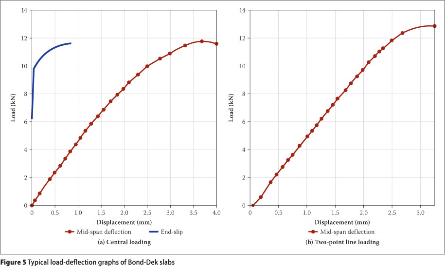
The shear bond parameters (mean shear stress per unit horizontal area (xm) and coefficient of frication ()) were established using the test method, developed by Patrick & Bridge (1990). The slabs were cast on the laboratory floor, and after 28 days the slabs were lifted onto the testing platform. In all tests, the composite slabs were one-way spanning and simply-supported on a span of 3.5 m. Tests were conducted using centre-line loading and two-point-line loading. The line loading was applied across the width of the specimen. For the two-point line loading, the shear span was maintained at 1.2 m. During testing, readings were taken of the vertical mid-span deflections and the horizontal differential movement or slip between the steel sheeting and the concrete slab using LVDTs and dial gauges. Typical graphs of the load vs mid-span deflections and end-slip for the Bond-Lok are shown in Figure 5.
Similar load-deflection graphs were developed for composite Bond-Dek slabs, and were documented by Mahachi (1997).
THEORETICAL CALCULATIONS
Substituting V and M in Eq (18) for a slab subjected to a two-point loading, with a shear span Ls yields the total load:
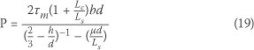
If, however, the coefficient of friction is neglected, then  and Eq (19) reduces to:

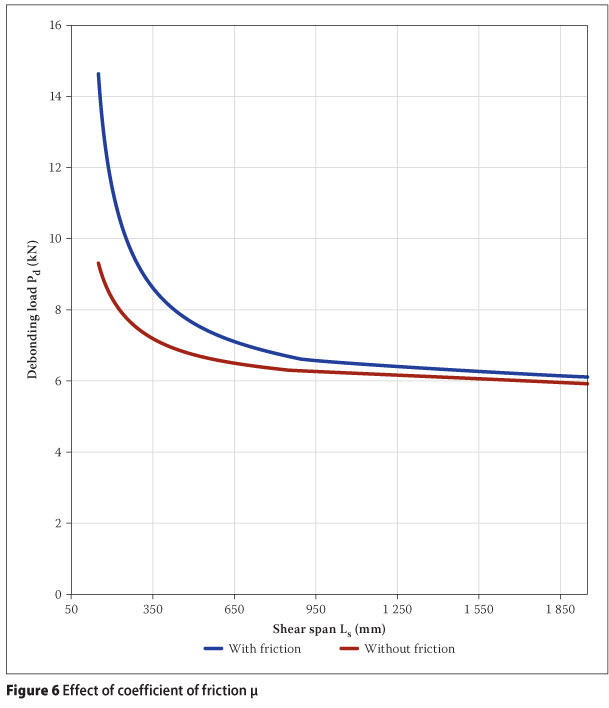
From Eq (19) it can be observed that the effect of is to increase the load at which debonding occurs, particularly for shorter spans.
Eq (18) is valid for:
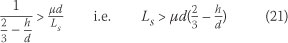
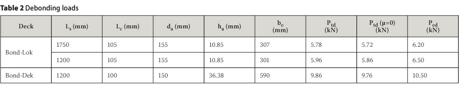
Using a value of = 0.2 and Tm = 0.095 JV7mm2 (determined as suggested by Patrick & Bridge 1990), the shear span for the Bond-Lok can be shown to be greater than 19 mm (Ls > 19 mm). This implies that Eq (18) is valid for all practical span lengths. A plot of Eqs (18) and (19) is shown in Figure 6. From the figure, the debonding load increases with decreasing shear span, Ls. Also, the effect of friction is greater for shorter spans than longer spans. As the shear span increases, the debonding load approaches a constant value of 6 kN. Values of the shear span (Ls), overhang length (Lc), average depth of the specimens (de) and the average position of the steel area ha are given in Table 2.
The equivalent sections of the Bond-Lok and Bond-Dek were calculated using the bending strength criteria. The equivalent widths (be) for the Bond-Lok and Bond-dek were found to be 307 mm and 590 mm respectively. Using the shear values of rm = 0.095 VV7mm2 for the Bond-Lok and rm = 0.12 mm2 for the Bond-Dek, the theoretical loads (Ptd) were calculated (see Table 2). It can be seen from this table that the theoretical debonding loads and the experimental loads (Ped) are acceptably close. Also the effect of the coefficient of friction is to increase the debonding load by only 1% to 2%, which is significantly small.
CONCLUSION
The use of fracture mechanics enables the calculations of the debonding load Pd to be carried out without recourse to several experimental tests. This formulation requires only two experimentally determined input parameters, i.e. the coefficient of friction and the shear strength per unit area τη. However, the effect of the coefficient of friction is negligible compared to shear strength. It is anticipated that using non-linear elasto-plastic fracture mechanics will enable the determination of the ultimate load without embarking on several experimental tests.
REFERENCES
Carpinteri, A 1981. A fracture mechanics model for reinforced concrete collapse. Proceedings, IABSE Colloquium on Advanced Mechanics of Reinforced Concrete, Delft, Netherlands, pp 17-30. [ Links ]
Carpinteri, A 1984. Stability of fracturing process in RC beams. ASCE Journal of Structural Engineering, 110: 544-558. [ Links ]
Ekberg, C E & Schuster, R M 1968. Floor systems with composite form reinforced concrete slabs. Proceedings, 8th Congress of the International Association for Bridge and Structural Engineers (IABSE), New York, pp 385-394. [ Links ]
Krige, G J & Mahachi, J 1995. Dynamic behaviour of composite floors. Journal of Construction Steel Research, 34(2-3): 249-269. [ Links ]
Luttrell, L D & Davison, J H 1973. Composite slabs with steel deck panels. Proceedings, 2nd Specialty Conference on Cold-Formed Steel Structures, Rolla, Missouri, US, pp 573-603. [ Links ]
Mahachi, J 1994. Response of composite bond-deck slabs to fatigue load. Proceedings, 5th International Conference on Steel Structures, Jakarta, Indonesia, pp 177-182. [ Links ]
Mahachi, J 1995. A comparison of two decking profiles subjected to fatigue load. Proceedings, RILEM International Conference on Dynamic Behaviour of Concrete Structures, Bratislava, Slovakia, pp 210-211. [ Links ]
Mahachi, J 1997. Vibration behaviour of composite deck slabs. PhD thesis, Johannesburg: University of the Witwatersrand. [ Links ]
Okamura, H, Watanabe, K & Takano, T 1975. Deformation and strength of cracked members under bending moment and axial force. Engineering Fracture Mechanics, 7: 531-539. [ Links ]
Okamura, H, Watanabe, K & Takano, T 1973. Application of the compliance concept in fracture mechanics. ASTM Special Technical Publication 536, Washington, US: ASTM, 423-438. [ Links ]
Patrick, M & Bridge, R Q 1990. Parameters affecting the design and behaviour of composite slabs. Proceedings, IABSE Symposium, Mixed Structures including New Materials, Brussels, Belgium, 5-7 Sept, pp 227-231. [ Links ]
Porter, M L & Ekberg Jr, C E 1976. Design recommendations for steel deckfloor slabs. ASCE, Journal of the Structural Division, 102(11): 2121-2136. [ Links ]
Schuster, R M & Ekberg, C E 1970. Commentary on the tentative recommendations for the design of cold-formed steel decking as reinforcement for concrete floor slabs. Research Report, Ames, Iowa: Iowa State University. [ Links ]
Schuster, R M & Ling, W C 1980. Mechanical interlocking capacity of composite slabs. Proceedings, 5th International Specialty Conference on Cold-Formed
Steel Structures (W W Yu, Ed.), St Louis, Missouri, US, pp 387-407. Wright, H D, Evans, H R & Harding, P W 1987. The use of profiled steel sheeting in floor construction. Journal of Construction Steel Research, 7(4): 279-295. [ Links ]
 Contact details:
NHBRC
PO Box 46'
Randburg
2125
South Africa
T: +27 11 317 0075
F: +2 7 8 6 63 0 8952
E: jeffreym@nhbrc.org.za
Contact details:
School of Civil Engineering & the Built Environment
University of Johannesburg
PO Box 524
Auckland Park
2006
South Africa
T: +27 11 559 3815
F: +27 11 559 3815
E: mdundu@uj.acza

DR JEFFREY MAHACHI, who is a member of the South African Institution of Civil Engineering (SAICE), is a registered professional engineer anc registered construction project manager, and is currently the Acting CEO of the NHBRC (Nationa Home Builders Registration Council). Jeffrey graduated with a PhD degree in structura engineering from the University ofthe Witwatersrand, a Masters in structural engineering from Surrey University (UK), a Masters in Information Technology from the University of Pretoria and a BSc Civil Engineering Hons from the University of Zimbabwe. He has worked as a research engineer at the CSIR Building Technology and has lectured at the University of the Witwatersrand. He has also written two books in structura engineering and presented several papers at international and loca conferences and seminars.

DR MORGAN DUNDU, who is a member of the American Society of Civil Engineers (ASCE), graduated from the University of Zimbabwe in 1990 with a BSc (Eng) in Civil Engineering. He graduated with an MSc and a PhD in Structura Engineering from the University of the Witwatersrand in 1996 and 2004 respectively He was a lecturer in Structural Engineering at the National University of Science and Technology (NUST) in Zimbabwe from 1997 to 1999, and at the University of the Witwatersrand from 2001 to 2003. Currently he is the Head of School of Civil Engineering and the Built Environment at the University of Johannesburg, and a senior lecturer in the Department of Civil Engineering Science.

