


Services on Demand
Article
 English (pdf)
 Article in xml format
 Article references
Indicators

Related links
-
 Cited by Google
 -
 Similars in Google
Share

 Permalink
Journal of the South African Institution of Civil Engineering
On-line version ISSN 2309-8775
Print version ISSN 1021-2019
J. S. Afr. Inst. Civ. Eng. vol.54 n.2 Midrand Jan. 2012
TECHNICAL PAPER
The effects of placement conditions on the quality of concrete in large-diameter bored piles
G C Fanourakis; P W Day; G R H Grieve
ABSTRACT
In South Africa, concrete in large-diameter bored piles is generally placed by discharging a high-flow concrete mix directly from the truck mixer and allowing the concrete to fall freely to the base of the pile hole. While certain site practices have been used by piling contractors for years, many engineers are not convinced of their acceptability.
In order to assess the effects of free-fall concrete placement, a series of tests were undertaken in which the properties of concrete placed in this manner were compared with the properties of conventionally placed concrete. The tests included an assessment of the effect of water and spoil in the pile hole at the time of casting, as well as poor placement techniques.
The results of this investigation indicate that casting of concrete in 50 mm and 400 mm of water in the bottom of the pile hole significantly reduced the compressive strength by approximately 50% and 80%, respectively. Furthermore, the effect of spoil at the bottom of the pile hole was dependent on the amount of water present.
Finally, a separate investigation, at a bridge site, indicated the free-fall placement technique to be at least as effective as the tremie technique.
Keywords: piles, concrete, quality control, site practices.
INTRODUCTION
Large-diameter (750 mm - 2 000 mm) bored (augered) piles are ideally suited to the stable residual soil profiles and deep water table conditions frequently encountered in the inland regions of South Africa. In many areas of the country, open holes can be augered without the need for temporary casing. The holes can safely be cleaned by hand and inspected in situ prior to the insertion of the reinforcing cage and placement of concrete. Typically, piles are cast by discharging high-flow concrete directly from the chute of the truck mixer using the deflector flap at the end of the chute to direct the concrete down the centre of the reinforcing cage in a continuous stream.
Most piling specifications and construction drawings clearly specify the class of concrete and the nature of the founding material for cast in situ bored piles. However, in most instances, little or no attention has been paid to site practices which can have a significant effect on the integrity of the pile. These include the method of concrete placement, the amount of water in the pile hole at the time of casting and the cleanliness of the pile socket. In an investigation by Alexander (1983), the unacceptable quality of pile concrete was attributed to the presence of excessive amounts of water at the bottom of the hole at the time of pouring the concrete.
In August 1991, the Research and Development Advisory Committee (RDAC) of the South African Roads Board commissioned a study of quality control during concrete placement in bored piles, with the intention of formulating rational guidelines for use by contractors and site supervision staff.
The main objectives of the programme were to investigate:
■ whether the free-fall or slow-pour placement methods result in a loss of strength or in segregation,
■ the extent to which the presence of water in the pile hole affects the strength of the concrete, and
■ what happens to any spoil remaining in the bottom of the pile hole during concrete placement and how this affects the integrity of the pile shaft.
A total of 20 trial "piles" were cast with varying amounts of water and/or spoil. Concrete cores from these piles were tested to determine their compressive strength, actual density and aggregate-binder ratios. In addition, the percentage excess voids was visually assessed. The effect of spoil on the contact at the end of the pile was also visually assessed.
This paper describes the procedures used during the tests and summarises the results obtained. Further details are given in the RDAC (1995) Report.
The effectiveness of the free-fall placement method, relative to the tremie method, was further assessed by comparing cores taken from piles of a particular bridge cast by either of these two placement techniques.
PRACTICE IN THE PILING INDUSTRY
In order to ascertain the current practice within the piling industry, a survey was conducted amongst four of the larger piling contractors on the Witwatersrand.
The contractors were unanimous that, where possible, large-diameter auger holes should be hand-cleaned as a matter of course. The purpose of hand-cleaning is to remove all loose material, as this may settle. Furthermore, the concrete should not be cast into more than 100 mm depth of standing water at the bottom of the pile hole. The minimum hole diameter which can be cleaned by hand was given as 750 mm, although hand-cleaning of a 600 mm diameter hole is possible in exceptional circumstances. Most contractors would recommend a reduction in the allowable end-bearing stresses for small diameter piles which are cleaned using a cleaning bucket and cannot be inspected in situ.
The amount of spoil that contractors would allow at the bottom of an end-bearing bored pile hole at the time of casting varied from nothing (if the hole was hand-cleaned) to 150 mm if the hole could not be cleaned. In the latter case the remaining material would be compacted by means of a tamper on the Kelly bar (the drill stem attached to the auger flight).
With regard to the method of concrete placement, contractors deemed it acceptable to cast the concrete by free-fall either straight from the chute of the truck mixer or using a short centralising tube. Only in the case of raking piles would the fall be limited, by means of trunking (pouring the concrete through a tube inserted within the reinforcing cage), to near the top of the concrete. None of the piling contractors would tremie concrete into a dry hole in order to prevent segregation. The upper few metres of the shaft would normally be vibrated on completion of the pour.
Most of the contractors interviewed felt that the requirements imposed by site supervision staff for the use of trunking or tremie tubes in dry vertical pile holes, and insistence on vibration of the concrete over the full length of the pile shaft, were unnecessarily stringent.
On the basis of the above survey, it would appear that the piling contractors were generally in full agreement with one another on the requirements for concrete placement. The differences in requirements from site to site appear therefore to be largely due to the opinions of site supervision staff. The fact that these findings were not based on measured results warranted this investigation.
CODE OF PRACTICE REQUIREMENTS
South African Codes
Most codes of practice for structural concrete lay down strict requirements for the general placing of concrete. Many of these requirements are aimed at preventing segregation and ensuring adequate compaction of the concrete. SANS 1200 G (1982) requires that concrete shall not be allowed to fall freely through a height of more than 3 m, unless otherwise approved and that compaction of the concrete is carried out by mechanical vibration. These requirements frequently find their way into piling specifications where completely different practices prevail.
SANS 1200 F (1983) (Piling) specifies a concrete slump of between 75 mm and 175 mm for various conditions, depending on the method of placement, spacing of reinforcement and diameter of the pile hole. The code recommends that internal vibrators should not be used, that concrete should be placed in the dry or by means of a tremie, that concrete should be placed in such a way that segregation does not occur, and advocates the use of a chute extending far enough into the hole to ensure that the concrete drops vertically when leaving the chute. In the case of raking piles, the chute is required to extend to the leading edge of the newly placed concrete.
Read together, these clauses from SANS 1200 F (1983) imply that the free-fall placement of concrete is permitted in vertical pile holes provided that the concrete is permitted to fall unobstructed down the centre of the pile.
ACI Manual of Concrete Practice: Concrete Piles
The 1973 version of the ACI Manual permits the placement of pile concrete at a continuous and rapid rate from the top of the hole, but only through a funnel hopper having a discharge opening smaller than the smallest pile section. Furthermore, the pile hole is to be free of all foreign matter, including "appreciable quantities of water". Vibration of concrete is recommended for reinforced piles.
Of all the manuals and specifications, the 1973 ACI Manual accords closest with common practice in the South African piling industry. The only significant difference is the recommendation that the concrete in reinforced piles be compacted by means of vibration.
In a later edition of this document (ACI 2000), and subsequent revisions, these clauses have been moved and re-titled. Unfortunately the clauses relating to methods of placement have been omitted in the 2000 and later versions of the ACI document.
EXPERIMENTAL METHODS OF THIS INVESTIGATION
Construction of piles
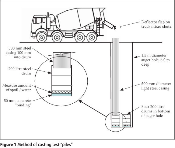
During the field work phase of the programme, which was carried out on 11 and 12 July 1991, 20 trial "piles" were cast using free-fall placement of concrete with various amounts of water and/or spoil at the bottom of the pile hole, as schematically indicated in Figure 1. The "piles" consisted of 200-litre steel drums placed at the bottom of a 6 m deep, 1.5 m diameter auger hole. The drums had a diameter of 560 mm and a depth of 870 mm. A 50 mm thick concrete blinding layer was cast at the bottom of each drum, to provide a solid base onto which the "pile" concrete could be cast. Before lowering the drums into the hole, measured amounts of water and/or spoil were placed into the drums to simulate inadequate cleaning of the pile.
Two types of spoil were used, one slightly cohesive and the other granular. The first was a silty andesite taken from the spoil of other pile holes being drilled on the site. This material classified as ML according to the Unified Soil Classification System, i.e. a silt of low plasticity. The second material was a crusher dust, which classified as SW/SM, i.e. a well-graded silty sand.
Concrete was discharged into the drums through a 500 mm diameter light-weight steel casing inserted about 100 mm into the top of each drum in turn, as shown in Figure 1. The hole was large enough to accommodate four drums at its bottom, and these were filled in turn. On completion of the pour, the drums were lifted from the hole and left to cure on the surface.
During casting, the concrete was directed down the centre of the casing using the deflector flap at the end of the chute of the truck mixer. The main stream of concrete reached the bottom of the "pile" without impinging on the sides of the casing. The casing simulated the side walls of an in situ pile hole. The rate of pour was rapid and the drop height was 6.8 m to the bottom of the "pile".
In the penultimate test, holes were cut through the steel casing and reinforcing bars were inserted horizontally across the casing to act as barriers to the free fall of the concrete and to encourage segregation. The concrete was discharged at the same rate as was used for the other tests.
In the final test, the concrete was poured slowly, falling from the chute of the truck mixer as individual blobs (the flow was not rapid and continuous). The rate of discharge was not quantified.
Mix design
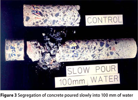
The mix proportions of the concrete, which was supplied by a ready-mix company, are indicated in Table 1.
The tests made use of four batches of the concrete delivered to site by separate truck mixers over the two-day period. Control samples of concrete were taken from each truck by casting concrete into drums on the surface and compacting the concrete by mechanical vibration.
Sampling, testing and visual inspection
Approximately two weeks after casting of the "piles", the drums were turned over and 100 mm diameter, 300 mm long core samples were drilled (vertically) through the bottom of each drum. After visual inspection and photography, the cores were submitted to an accredited commercial laboratory for testing.
Compressive strength tests were carried out on all core specimens at an age of 37 or 38 days after casting. In addition, the actual density (water-soaked density of the uncapped core) was determined and the percentage of excess voids was assessed visually. These tests were carried out in accordance with the recommendations contained in CSTR (1987).
The aggregate-binder ratios were determined on nine samples of concrete cast through various depths of water and on one of the control samples using the soluble silica test method, as detailed in BS 1881: Part 124: 1988.
After the concrete cores had been taken, the bottom of the drums containing spoil were cut away to observe the extent to which the spoil at the bottom of the "pile hole" had been displaced by the falling concrete. The thickness of the remaining spoil was measured at 100 mm intervals around the perimeter of the "pile". After removal of the layer of blinding concrete, the area of intimate contact between the "pile" concrete and the bottom of the hole (i.e. the area over which the spoil had been completely displaced) was estimated.
RESULTS
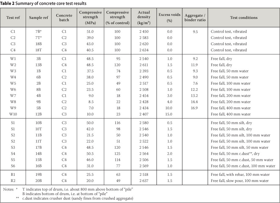
Table 2 summarises the conditions under which the various "piles" were concreted, and the laboratory test results.
DISCUSSION
This section of the paper discusses each of the research objectives (listed earlier) in turn.
Segregation due to free-fall placement
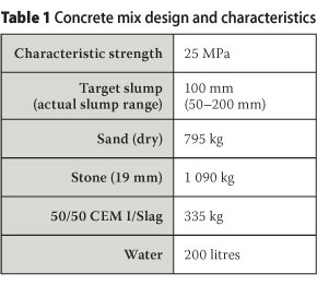
Figure 2 shows cores drilled through the bottom of the "piles" cast through various depths of water in the "pile hole" at the commencement of the pour. The sample reference numbers are indicated on these cores (left to right: 5B, 4B, 2B, 1B, 3B, 7T and 7B).
In this figure, the bottom of the "pile" is facing away from the reader. The contact between the 50 mm blinding concrete cast in the drums and the "pile" concrete is visible in some of the cores.
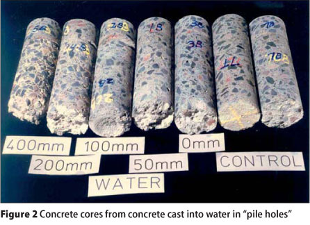
In all these cores, there was an even distribution of coarse aggregate, despite the higher void content of the concrete for greater water depths. A similar, even distribution of aggregate was observed in Test R1 which simulated the effect of allowing concrete to impinge on the reinforcing cage during free fall into 100 mm of water. The only case where segregation was evident was where the concrete was poured slowly into 100 mm of water as shown in Figure 3.
In Figure 3 the bottom of the core is to the left of the picture. The disc of blinding concrete has separated from the "pile" concrete. The "pile" concrete shows classical signs of segregation, with unbonded aggregate at the toe of the "pile" and decreasing aggregate content with the accumulation of fines and laitance towards the top of the pour.
From these observations it was concluded that, despite the variance in slumps (50 mm to 200 mm), the pouring of concrete at the normal (rapid) rate resulted in sufficient turbulence (and mixing) at the bottom of the hole to prevent segregation of the concrete mix, even where the fall of the concrete was interrupted by impact with the reinforcing steel. This confirms the findings of separate studies carried out by STS Consultants (1994) and
Turner (1979), where the free fall heights were 18 m and 15 m respectively. However, where the concrete was poured slowly, this turbulence was absent and no re-mixing occurred at the bottom of the hole. These discharging practices may be compared to opening a tap and discharging water into a half-full basin of water. If the stream of water is continuous, the waters mix. If the water flow is drop by drop, little mixing occurs.
Where water was present, the fine aggregate and cement paste were removed by the upward percolation of water through the concrete, leaving un-bonded coarse aggregate at the bottom of the hole.
Effect of water in "pile hole"
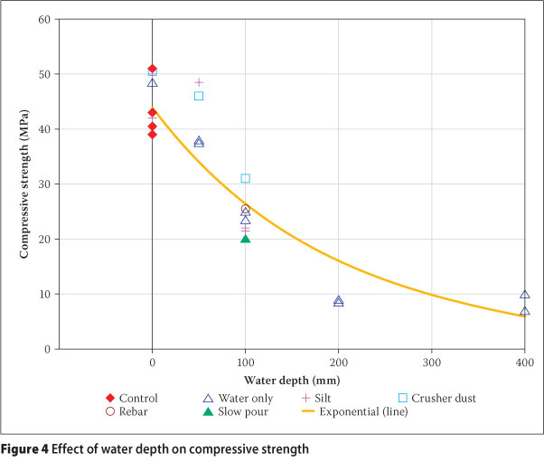
The effect of the depth of water in the "pile hole" prior to commencement of concreting on the strength of the concrete is shown in Figure 4. An exponential curve was fitted to the data.
Figure 4 clearly demonstrates that the free fall of concrete in dry holes did not affect the strength of concrete. However, free-fall casting of concrete into water adversely affected concrete strength. As little as 100 mm of water in the bottom of the "pile hole" resulted in an approximately 50% decrease in the strength of the concrete. For water depths in excess of 200 mm, the concrete strength was reduced by approximately 80%. Further increases in the amount of water in the bottom of the "pile hole" appear to have little effect. This was probably caused by the concrete not being able to absorb the excess water which was carried upwards during pouring of the concrete.
The samples containing crusher dust "spoil" generally achieved higher strengths at particular water depths. This was probably the result of the crusher dust mixing with the concrete and any water present, on impact, as the concrete was poured, hence reducing the formation of voids. However, this was not the case in the samples containing silt "spoil".
With reference to Table 2, tests were performed on cores taken from both the top and bottom of drums 10 and 11. It is interesting to note that the strength of the top and bottom cores from drum 11 differed only by 0.5 MPa. However, in the case of drum 10, the strength of the bottom core exceeded that of the top core by 8 MPa. The latter result was generally expected due to bleeding of the concrete. With the methodology employed, it was not possible to investigate the persistence of this effect up the length of the "pile" shaft or to assess any increase in bleed of the concrete with the increase in the amount of water in the hole.
The inclusion of reinforcing bars as obstructions in the casing appeared to have no effect on the concrete strength, whilst the slow pouring resulted in a slight reduction in strength.
No trend was identified when comparing the results deriving from each of the control samples. The declining trend shown in Figure 4 was not improved when normalising the compressive strength by expressing it as a percentage of the compressive strength of the relevant control sample.
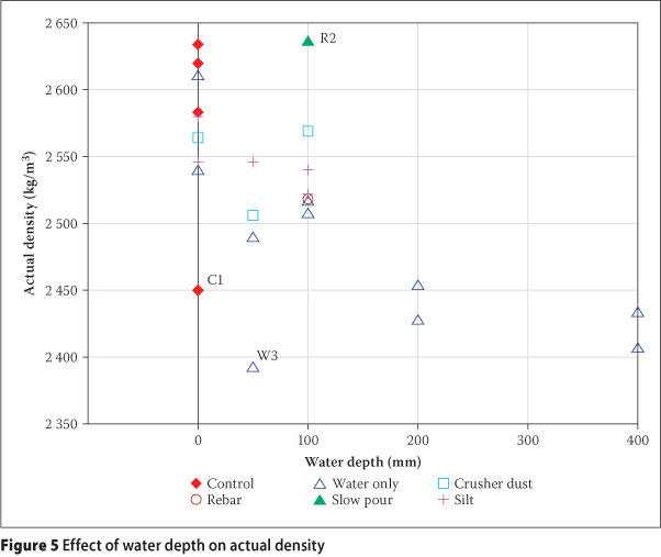
Figure 5 indicates the effect of water on the actual density of concrete in the cores. It is evident from this figure that the actual density of the concrete was, on the whole, adversely affected by the depth of water in the "pile hole".
As is evident from Figure 5, 200 mm of water in the "pile hole" reduced the concrete actual density by approximately 90 kg/m3. Increasing the amount of water to 400 mm had an insignificant additional effect. It is interesting to note that the relatively wide range of densities for water depths of 0 and 50 mm are not reflected in the compressive strength results shown in Figure 4. Furthermore, the results of tests on samples C1, W3 and R2 are "outliers" as they fall out of the band of one standard deviation (s = 80) either side of a linear regression line. There is no apparent reason for these "outliers". The exclusion of the "outlier" samples resulted in an increase in the linear correlation coefficient, r2 (from 0.369 to 0.701). This correlation was not improved by normalising the actual density by expressing it as a percentage of the density of the relevant control sample.
The relationship between actual density and compressive strength of concrete yielded a poor correlation coefficient (r2 = 0.2).
Figure 6 indicates that the percentage excess voids increases with depth of water. The control samples were excluded from this relationship as they were vibrated. An exponential curve was fitted to the data.
Referring to Figure 6, for water depths of less than 100 mm, the excess voids were typically less than 2% and are thought to be due to the entrapment of air. However, as the depth of water increased, the excess voids increased to between 10% and 15%. The reason for this trend is that the water at the bottom of the "pile hole", due to its relatively low density, rose into the concrete (during pouring), displacing the mortar and creating voids. Hence, the greater the volume of water in the "pile hole", the greater the volume of excess voids in the concrete.
In contrast to Figures 4 and 5, however, no plateauing was evident with water depths in excess of 200 mm. The increase in voids with increasing water depth is clearly visible in the photograph in Figure 2 where, for water depths of 200 mm and 400 mm in particular, the matrix to the coarse aggregate appears to have been eroded during the drilling operation, giving visual confirmation of the low strength of the paste.
No correlation was found to exist between the percentage excess voids and actual density.
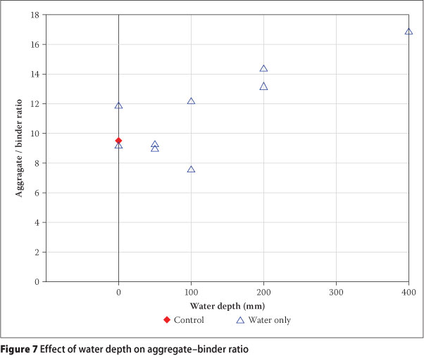
Figure 7 shows the correlation between the depth of water in the "pile hole" and the aggregate-binder ratio. For water depths of less than 100 mm, the average aggregate-binder ratio was of the order of 10. However, this increased to as much as 17 where the concrete was placed through 400 mm of water. This trend is attributable to the upward displacement of mortar, from amongst the coarse aggregates in the lower section of the "pile hole", caused by the upward movement of water through the concrete during pouring. Hence, the more water present, the more mortar displaced.
Displacement of spoil
As shown in Table 2, the bottom of "pile holes" for tests S1 to S6 contained 50 mm of spoil. By cutting away the bottom of these drums, the percentage of contact between the "pile" concrete and the blinding was estimated and the distribution of spoil was observed.
Table 3 shows the percentage of the area of the base of the "pile" which was in intimate contact with the bottom of the "pile hole", that is the area over which the spoil had been displaced. Higher percentage contacts are more favourable from a founding point of view.
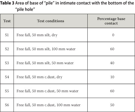
In the case of both the silty spoil material and the crusher dust, casting of concrete onto 50 mm of dry spoil resulted in total separation between the "pile" concrete and the base of the "pile hole". However, the contact area increased to between 40% and 60% in the tests where 50 mm or 100 mm of water was added to the base of the "pile hole" together with the spoil.
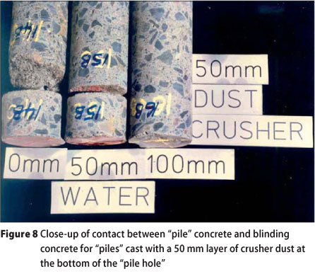
Figure 8 shows the contact between the blinding concrete at the base of the drum (representing the in situ founding material) and the "pile" concrete for "piles" cast onto a 50 mm layer of crusher dust at the bottom of the "pile hole". The dry crusher dust (0 mm water - left core sample) was trapped between the "pile" concrete and the bottom of the "pile hole", resulting in a total lack of contact of the "pile" with the founding material. With 50 mm of water in the "pile hole", the crusher dust over the middle of the hole was displaced by the falling concrete and this material was assimilated into the "pile" concrete as a result of the remixing of the concrete as it falls to the bottom of the hole. With 100 mm of water in the hole, the contact over the central portion of the "pile" was visually tight. However, the strength of the "pile" concrete had reduced to 77% of that of the control sample (40.5 MPa to 31 MPa) and the bearing area was reduced by about 50% due to trapping of crusher dust around the perimeter of the "pile" base.
MORE RECENT COMPARATIVE OBSERVATIONS OF CONCRETEQUALITY IN PILES PLACED USING FREE-FALL OR TREMIE METHODS
A number of questions typically arise when the free-fall method of placement is proposed by a contractor, questions which may not adequately be answered by the findings in the early research described above. For example, the engineer might enquire whether the use of tremie techniques might not produce better results. Similarly there might be concerns as to whether the relatively good compaction observed in the cores taken from the free-fall trials would extend right to the interface with the side of the pile excavation.
In an attempt to answer such questions, access was obtained to cores taken from the construction of the widening of Garsfontein Bridge, which was part of the widening of the
N1 between Atterbury and Rigel Avenue off-ramps in Pretoria. On this project some of the piles were placed in wet conditions, and in such cases use was made of tremie tubes. The majority of the pile holes were, however, dry and these were placed using free-fall placement.
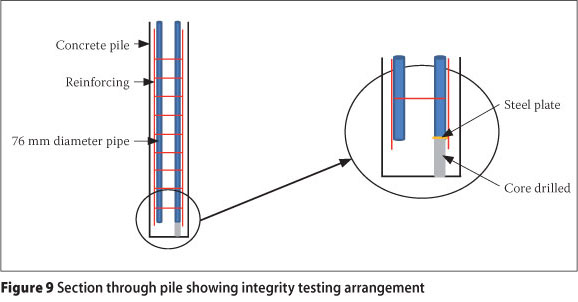
In all cases, three 76 mm diameter pipes were cast into the concrete for each pile, for subsequent integrity testing. These pipes were tied to the inside of the reinforcement cage and thus were situated about 70 mm from the interface between the pile and the soil. These pipes were sealed at the base with a steel plate to prevent intrusion of concrete. Subsequent to the successful integrity testing with ultrasonic techniques, cores were drilled through the base of one of these pipes per pile, through the concrete below the bottom of the cage and into the end-bearing in situ material as an additional integrity check. Typically these cores were taken about 7 m below ground level. Figure 9 shows details of the integrity testing arrangement of these piles.
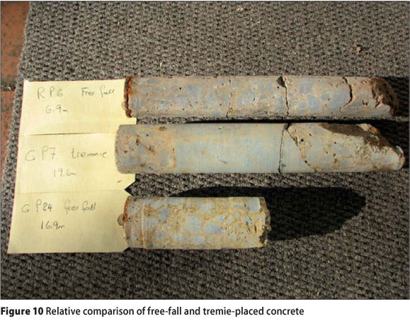
Visual inspection was done of a random selection of a number of such lengths of core, both from free-fall-placed, as well as tremie-placed concrete piles. Generally the degree of compaction as assessed from the visible void content for the free-fall placing was at least equal to that of the tremie-placed concrete, although the concrete with the poorest compaction was generally from piles cast using tremie placing. Figure 10 illustrates that the free-fall concrete was as well compacted as the tremie-placed concrete.
CONCLUSIONS
On the basis of the above experimental data, the following conclusions were reached:
■ No segregation of the concrete (in the sense of an accumulation of aggregate at the base of the pour) was observed when the concrete was discharged from the truck mixer at a rapid rate, even when the concrete was permitted to impinge on the reinforcing "cage". Clear signs of segregation were evident when the concrete was poured slowly into 100 mm of water. It appears that the rapid discharge of concrete results in "remixing" of the concrete in the bottom of the "pile hole".
■ Free-fall placement of concrete into dry "pile holes" had no apparent effect on the compressive strength of the concrete compared to that of the four control samples.
■ Casting of concrete through 50 mm of water at the bottom of the "pile hole" reduced the compressive strength by an average of approximately 15%.
■ Casting of concrete through 100 mm and 400 mm of water in the bottom of the "pile hole" significantly reduced the compressive strength of the concrete by approximately 50% and 80% respectively.
■ In addition to having an adverse effect on the strength of the concrete, casting of concrete into more than 100 mm of water was detrimental to the actual density of the concrete, the percentage excess voids and the aggregate-binder ratio.
■ As little as 50 mm of dry spoil at the bottom of the "pile hole" negated all direct contact between the "pile" concrete on the underlying founding stratum. Wet spoil was more readily displaced by the concrete, but still resulted in significant reductions in base bearing area mainly around the perimeter of the "pile" base.
■ Interruption of the free fall of the concrete by a moderate amount of reinforcement appeared to have a negligible effect on the quality of the concrete, provided the rate of pour was reasonable.
■ The observations of the relative compaction of concrete taken from piles placed using free fall versus those placed using tremie techniques, demonstrated that free-fall placing over a range of depths was an acceptable, if not preferable, technique. On the strength of this limited research, which included concrete mixes of different slumps and compressive strengths, it was concluded that the current practice of free-fall placement of concrete in clean, dry pile holes has no detrimental effect on the quality of the concrete. It is, however, recommended that such techniques should not be used when the depth of water at the bottom of the pile hole exceeds 75 mm.
ACKNOWLEDGEMENTS
The research was carried out under the auspices of the then Research and Development Advisory Committee of the South African
Roads Board. The fieldwork was sponsored by specialist geotechnical contractors Esor. Both sponsorships are gratefully acknowledged.
REFERENCES
ACI 1973. Manual of concrete practice: concrete piles. ACI Committee 543, Detroit, US: American Concrete Institute. [ Links ]
ACI 2000. Design, manufacture and installation of concrete piles. ACI Committee 543, Farmington Hills, US: American Concrete Institute. [ Links ]
Alexander, M D 1983. Report on condition of pile concrete in selected piles of silo No 2 at Jupiter Bulk Cement Handling Site. Prepared for Ground Engineering and Piling Limited. [ Links ]
BS 1881: Part 124: 1988. Testing concrete. Methods for analysis of hardened concrete. London: British Standards Institution. [ Links ]
CSTR 1987. Concrete core testing for strength. Concrete Society Technical Report No 11, including Addendum, London: Concrete Society. [ Links ]
RDAC 1995. Quality control of concrete placement in bored piles. South African Roads Board Research and Advisory Committee, Report No 91/453, Compiled by Jones and Wagener, Rivonia (Report No. G1/93/1932). SANS 1200 F:1983. Standardized specification for civil engineering construction. Section F: Piling. Pretoria: South African Bureau of Standards. [ Links ]
SANS 1200 G:1982. Standardized specification for civil engineering construction. Section G: Concrete (structural). Pretoria: South African Bureau of Standards. [ Links ]
STS Consultants 1994. The effects of free fall on concrete in drilled shafts. Report to the Federal Highway Administration, Chicago: STS Consultants. [ Links ]
Turner, C D 1979. Unconfined free fall of concrete. Journal of the American Concrete Institute (ACI), Dec. 1979, pp 975-976. [ Links ]
 Contact details:
Department of Civil Engineering Technology,
University of Johannesburg
PO Box 17011,
Doornfontein,
2028,
South Africa
T: +27 11 559 6416,
F: +27 11 559 6057
E: georgef@uj.ac.za
Contact details:
Jones & Wagener (Pty) Ltd Consulting Engineers PO. Box 1434,
Rivonia,
2128,
South Africa
T: +27 11 519 0200
E: day@jaws.co.za
Contact details:
344 Delphinus Street,
Waterkloof Ridge,
Pretoria,
018'
T: +27 12 460 3503
E: grahamgrieve46@gmail.com

PROF GEORGE FANOURAKIS is an Associate Professor in the Department of Civil Engineering Technology at the University of Johannesburg, South Africa. He received the degrees MSc (Eng) from the University of the Witwatersrand anc DTech (Eng) from the University of Johannesburg. He is a Chartered Civil Engineer and Member ofthe Institution of Civil Engineers (UK), and a Fellow of the South African Institution of Civil Engineering (SAICE). His primary teaching and research interest areas are concrete technology and geotechnical engineering. Prof Fanourakis heads the Materials, Geotechnica and Transportation Engineering Research Group at the university. He is a member of the South African Bureau of Standards Geotechnical Standards Committee (SABS SC 59P). In 2006 he received the SAICE award for best paper published in the Journal ofthe South African Institution of Civil Engneering.

PETER DAY is Chairman of Jones &Wagener Consulting Engineers where he has worked as a geotechnical engineer for the past 33 years. One of his delights in life is finding meaningfu solutions to practical problems. He is an Honorary Fellow of SAICE (South African Institution of Civil Engineering) and has served as chairman ofthe Institution's Geotechnica Division. He also served as Vice-President for Africa of the ISSMGE (Internationa Society for Soil Mechanics and Geotechnical Engineering). Currently he is chairman of the South African Bureau of Standards Technical Committee 98 (SABS TC98) for Structural and Geotechnical Design Standards.

DR GRAHAM GRIEVE graduated with a degree ir civil engineering from the University of Cape Town in 1970. After working in the Netherlands for one year, and at the Coastal Research Unit of the Council for Scientific and Industrial Research in Stellenbosch, he served as resident engineer on a road and bridge contract in the Limpopo Province before joining JS Bergman and Partners in Pretoria in 1978 where he was responsible for materials testing and designing of road projects. He received an M.Ing degree in civil engineering from the University of Pretoria in 1984, while he was Director of Laboratory Services at the Portland Cement Institute (PCI). In 1990 he became Executive Director of the PCI (which in 1996 was renamed to the Concrete & Cement Institute (C&CI)), and retired as Managing Director of the C&CI in 2008. Dr Grieve was awarded a PhD from the University of the Witwatersrand in 1991 for his work on the practical use of fly-ash, which entitled him to full membership of the Institute of Concrete Technologists in the United Kingdom.

