


Services on Demand
Article
 English (pdf)
 Article in xml format
 Article references
Indicators

Related links
-
 Cited by Google
 -
 Similars in Google
Share

 Permalink
Journal of the South African Institution of Civil Engineering
On-line version ISSN 2309-8775
Print version ISSN 1021-2019
J. S. Afr. Inst. Civ. Eng. vol.54 n.2 Midrand Jan. 2012
TECHNICAL PAPER
A step towards standardising accelerated corrosion tests on laboratory reinforced concrete specimens
G Malumbela; P Moyo; M Alexander
ABSTRACT
Natural steel corrosion of reinforced concrete (RC) structures is a slow process which researchers find necessary to accelerate in laboratory tests to obtain needed damage in a short time. Regrettably, there is no standard procedure for accelerating steel corrosion in RC specimens. Researchers therefore continue to use various techniques to accelerate it. Unfortunately, structural damage and rate of steel corrosion are dependent on the accelerated corrosion technique used. Despite that, results obtained by researchers are applied by structural engineers and asset managers to in-service structures. This paper reviews previous techniques used to accelerate steel corrosion. Where possible it proposes standard procedures to accelerate steel corrosion. In other instances it points out needed further research. One of the procedures recommended in the paper is to contaminate selected faces of RC specimens with chlorides, as opposed to immersing samples in NaCl solution or adding chlorides to concrete mixes. It is also recommended to allow specimens to sufficiently dry during steel corrosion so as to promote steel corrosion.
Keywords: accelerated corrosion, reinforced concrete, deterioration
INTRODUCTION
Steel corrosion causes the most damage in in-service RC structures near the marine environment. However, in laboratory terms, the process of natural steel corrosion is very slow, needing tens of years to cause reasonable structural damage. For example, François & Arliguie (1998), Castel et al (2003), Vidal et al (2007) and Zhang et al (2009a,b; 2010), who allowed their laboratory specimens to corrode naturally, had to wait for four years for steel corrosion to start and an additional two years for first cracking to occur. They only obtained reasonable structural damage after 20 years. These times are not often afforded in laboratory tests. Researchers, understandably, have and continue to use various techniques to accelerate steel corrosion so as to shorten the needed testing time. In doing so they anticipate that structural damage under accelerated tests is proportional to damage caused by natural steel corrosion.
It should be pointed out that results obtained by researchers on laboratory specimens that are subjected to accelerated corrosion tests are often passed on to structural engineers and asset managers to apply them to real RC structures which corrode in the field. If they are not applicable to those structures then there is likelihood for engineers to authorise repairs of corroding RC structures at dangerous levels of steel corrosion or when load-bearing capacities of structures are still adequate. For the safety of occupants of corroding RC structures, as well as to minimise costs from unnecessary repairs, there is need to understand well how to apply (if at all applicable) results from accelerated laboratory tests to in-service structures.
This paper discusses various techniques that are often used in research laboratories to accelerate steel corrosion. It then compares conditions and results between the procedures, and where possible, associates them with those from in-service conditions. Finally, it proposes and points out needed research to establish a standard procedure that should be used in laboratories to study behaviour of corroding RC structures. The focus of the paper is on steel corrosion caused by chloride attack. It is also aimed at steel corrosion carried out with the intention to understand structural behaviour of corroding RC members. Issues regarding effects of accelerated corrosion on the electrochemical nature of RC elements were discussed in detail by Poursaee & Hansson (2009). In their discussion, they strongly discouraged accelerating steel corrosion for the reason that it harms the electrochemical nature of concrete. If concern is limited to the electrochemistry of concrete then adequate results can be obtained within a reasonable time frame, even when corrosion is natural. For example, a period of four years which François & Arliguie (1998), Castel et al (2003), Vidal et al (2007) and Zhang et al (2009a,b; 2010) had to wait for their specimens to start corroding is achievable in laboratory tests. However, and as previously mentioned, if interest is on structural behaviour then much longer testing periods are required. Accelerated corrosion is therefore often used to reduce this time of testing. The following section discusses various procedures used to accelerate steel corrosion and how they affect structural behaviour.
ACCELERATED DEPASSIVATION OF STEEL
Concrete normally has an alkaline environment that protects embedded steel from corrosion. This environment can be destroyed by carbonation or by chloride attack. As already mentioned, it may take some years for sufficient chlorides to ingress cover concrete and de-passify steel. To hurriedly depassify it, some researchers opted to mix concrete with chlorides ranging from 1% (Mangat & Elgarf 1999) to 5% (El Maaddawy & Soudki 2003) by weight of cement. Others immersed their cured samples in tanks with NaCl solution with concentration from 3% (Cairns et al 2008) to 5% (Cabrera 1996) by weight of the solution. Levels of concentration of chlorides were often selected to simulate chloride concentration of seawater which has a salt concentration of about 3.5%. Note that both procedures above were used by some researchers (Azad et al 2007; Mangat & Elgarf 1999; Cairns et al 2008). According to Poursaee & Hansson (2009), if chlorides are added to a concrete mix, de-passivation of steel is immediate. Therefore the time required for steel to depassivate, which is often used in service life models, does not exist (Tuutti 1980). Understandably, Poursaee & Hansson (2009) strongly discouraged this procedure. They rather recommended that steel firstly be allowed to passivate before introducing chlorides to break the passive film.
One important element not discussed by Poursaee & Hansson (2009), but which emphasises their recommendation, is that adding chlorides to concrete results in uniform distribution of corrosion agents around the steel. Under natural steel corrosion, however, limited faces of a structure are often exposed to chloride attack. In addition, chlorides and other deleterious compounds are purposely excluded from concrete mixes in practice.
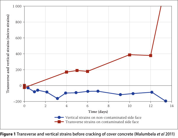
In an attempt to better represent natural steel corrosion, some researchers contaminated selected faces of their cured specimens with chlorides. This was achieved by either building NaCl ponds on surfaces of specimens to be contaminated (Yoon et al 2000; Malumbela et al 2009) or by selectively spraying them with salt solution (Zhang et al 2009a,b; Zhang et al 2010; Rio et al 2005). Under this selective contamination of RC specimens with chlorides, Malumbela et al (2011), Yuan & Ji (2009) and Yuan et al (2007) found steel corrosion to be localised within the direction of ingress of corrosion agents. Its implication was that compared to non-contaminated faces, larger tensile strains (especially prior to cover cracking) were measured on contaminated faces of concrete as shown in Figure 1 (Malumbela et al 2011).
In modelling time to cover cracking, Yuan & Ji (2009) proposed that the remaining bar diameter should be taken as elliptical shaped rather than circular, as used by many other researchers (Liu & Weyers 1998; El Maaddawy & Soudki 2007; Bhargava et al 2006). Jang & Oh (2010) and Malumbela et al (2011) demonstrated that assuming uniform loss of steel underestimates pressure applied by expansive corrosion products and hence overestimates resistance of the cover concrete to cracking that is observed under partial surface steel corrosion. Following discussions by Poursaee & Hansson (2009), Yuan & Ji (2009), Yuan et al (2007), Jang & Oh (2010) and Malumbela et al (2011), it is recommended that in accelerated corrosion tests:
i. Steel should be allowed to passivate before adding chlorides to concrete. This is equivalent to saying chlorides should be added externally and not be mixed with concrete.
ii. Only selected faces of concrete elements should be contaminated with chlorides. Specimens should not be submerged in salt solutions. This point will be further discussed later.
IMPRESSED CURRENT DENSITY
Corrosion of steel embedded in concrete occurs by an oxidation-reduction reaction. Loss in steel occurs at the anode where electrons are also produced and transferred to the cathode. This flow of electrons produces a small current which is often divided by the surface area of an anode to give current density. According to Andrade & Alonso (2001) and Alonso et al (1998), current density due to natural steel corrosion is often between 0.1 and 10 μA/cm2 but occasionally reaches 100 μA/cm2. Researchers make use of this current to speed up laboratory corrosion tests. They apply a larger direct current and adjust it such that reinforcing steel bars which they need to corrode are connected to a positive terminal, and an artificial steel bar/plate is connected to a negative terminal. Reinforcing steel bars therefore become the anode and the artificial steel bar/plate becomes the cathode. A salt electrolyte (aqueous NaCl or CaCl2) is used to provide electrical contact between the anode and the cathode. This procedure increases electrons that flow around the circuit. Bear in mind that from basic chemistry each reaction (oxidation/reduction) should always be balanced. It is clear that to balance increased electrons from the impressed current, more cations and anions are respectively produced at the anode and at the cathode. At the anode, this is achieved by an increased rate of loss of steel.
The level of impressed current density has varied greatly [from 3 A/cm2 (Alonso et al 1998) to 10400 A/cm2 (Almusallam et al 1996)] between researchers. Assuming proportional structural damage due to accelerated tests, a level of damage caused by a current density of 3 A/cm2 over a period of one year can be obtained within two hours when a current density of 10400 μA/cm2 is used. Should accelerated tests give proportional damage then there is little value in using low rates of steel corrosion.
To assess the effect of varying current densities on the proportion of structural damage, Mangat & Elgarf (1999) measured slopes of load-deflection curves of RC specimens that were corroded with corrosion rates from 1000 to 4000 μA/cm2. The concrete mix that they used for RC specimens had 1% NaCl salt by cement weight, and during the accelerated test their specimens were immersed in a 3.5% NaCl solution. At lower levels of steel corrosion (<10% mass loss), Mangat & Elgarf (1999) found little influence of corrosion rates on the stiffness of corroded specimens. However, at mass losses of steel above 10%, slopes of load-deflection curves or stiffness of corroded RC specimens were severely influenced by the rate of steel corrosion. For example, at a mass loss of steel of 15%, a specimen that was corroded with a current density of 4000 μA/cm2 needed a load of 26 kN to cause a deflection of 3 mm (stiffness = 8.7 kN/mm). At the same level of steel corrosion, a similar specimen that was corroded with a current density of 1000 μA/cm2 exhibited a deflection of 3 mm at a load of 38 kN (stiffness = 12.7 kN/mm). This indicates that at the same level of steel corrosion, there was a larger loss in stiffness of specimens that were corroded under a higher current density. Therefore, if loss in stiffness were to be used to predict levels of steel corrosion, its relation with corrosion levels from accelerated tests would result in engineers underestimating levels of steel corrosion in in-service structures.
Mangat & Elgarf (1999) asserted that for accelerated corrosion tests in laboratory specimens, especially when the target level of steel corrosion is high, the lowest practical corrosion rate should be used to accelerate reinforcement corrosion. Since they used corrosion rates that ranged from 1000 to 4000 A/cm2, it is reasonable to assume from their results that a corrosion rate that is below 1000 A/cm2 is appropriate for laboratory tests. One of the drawbacks with this work is that it used parameters that were only measured at the end of the corrosion process. It therefore does not provide the influence of the rate of steel corrosion on the much-needed rate of change of parameters with an increase in the level of steel corrosion. In addition, the corrosion process used does not give partial surface steel corrosion which Yuan & Ji (2009), Yuan et al (2007) and Jang & Oh (2010) contended to be more representative of in-service conditions.
El Maaddawy & Soudki (2003) conducted another research to find an impressed current density that can produce desired structural damage in a short time without excessively altering structural response under natural steel corrosion. In their work the researchers used rate of widening of corrosion cracks and average mass loss of steel at the end of corrosion tests as parameters that indicate corrosion damage. Crack widths were measured at one point on side faces of specimens using a demountable mechanical (demec) gauge with a gauge length of 50 mm. Depassivation of steel was accelerated by mixing concrete with 5% NaCl by weight of cement. Current densities assessed ranged from 100 to 500 μA/cm2.
They found that at corrosion crack widths below 0.03 mm (which corresponded to a theoretical mass loss of steel from Faraday's Law of 0.8%), specimens corroded using various current densities which exhibited a similar rate of expansion of the cover concrete. At larger crack widths (>0.03 mm), they found specimens subjected to current densities above 350 A/cm2 to exhibit a significantly larger rate of widening of corrosion cracks (up to four times) than specimens that were subjected to current densities below 200 μA/cm2. Interestingly though, they found that regardless of the level of impressed current density used, average mass losses of steel at the end of corrosion tests were within 4% of theoretical mass losses of steel predicted from Faraday's Law. These results indicate that if corrosion crack widths were to be used to predict levels of steel corrosion, relations between crack widths and mass loss of steel from highly accelerated tests would underestimate steel corrosion in in-service structures. Assuming a linear increase in mass loss of steel and crack widths, under highly accelerated tests (500 A/cm2), they found a crack width of 1 mm to correspond to mass loss of steel of 7.3%. However, at lower corrosion rates (100 A/cm2 and 200 μA/cm2) a crack width of 1 mm was found to correspond to a mass loss of steel of 13.3%. El Maaddawy & Soudki (2003) concluded that an impressed current density below 200 A/cm2 does not excessively alter the structural performance of corrosion-affected RC specimens that would be observed under natural steel corrosion.
It should be mentioned that El Maaddawy & Soudki (2003) initially observed two corrosion cracks near each corroding bar and each crack propagated parallel to the bar. These cracks were either on the top face or on the side face. Interestingly, when the level of steel corrosion was increased, a third crack appeared next to a corroding bar, but on a face that was uncracked. This indicates that the pattern of corrosion cracks changed with an increase in the level of steel corrosion. Similar change in crack patterns as steel corrosion increased was reported by Malumbela et al (2010a). They found that when a second crack appeared, the first crack ceased to widen. Certainly, specimens that exhibit this crack pattern will have narrower cracks than those that only exhibit a single crack. This was also found by Zhang et al (2010). This argument certainly questions the use of crack widths without full understanding of crack patterns to specify the level of current density to be used in accelerated corrosion tests. Bear in mind that current density used by Malumbela et al (2010a) was 189 A/cm2 which is within the limit proposed by El Maaddawy & Soudki (2003).
Contrary to findings by El Maaddawy & Soudki (2003), Alonso et al (1998) found that, for a chosen crack width, higher penetration depth (more than three times larger) of steel was needed when applying a current density of 100 A/cm2 than when applying a density of 3 A/cm2. This implies that crack widths increase faster with a lower corrosion rate (3 A/cm2) than with a higher corrosion rate (100 A/cm2). Somewhat similar to findings by Alonso et al (1998), Malumbela et al (2010b) found that, at high sustained loads, when steel corrosion is firstly accelerated and then allowed to run naturally, the rate of the widening of corrosion cracks does not change, but the rate of steel corrosion reduces significantly. Malumbela et al (2010b) attributed this to natural steel corrosion producing dryer products that are not easily exuded to the exterior faces of concrete.
Results by El Maaddawy & Soudki (2003), Mangat & Elgarf (1999), Malumbela et al (2010a,b) and Alonso et al (1998) indicate that the effect of the level of current density on structural behaviour is contentious. Further research to clarify this is therefore necessary.
TYPE OF CATHODES
Whilst anodes are simply steel bars that are required to corrode, various types of cathodes have been used in accelerated corrosion tests. In some research, metal bars embedded in concrete were used (El Maaddawy et al 2005b; El Maaddawy & Soudki 2003; Badawi & Soudki 2005). In others, metal bars were placed on external surfaces and inside a chloride salt electrolyte (Malumbela et al 2009; Ballim et al 2001). These bars were of different dimensions and made from different metals. The most used metals, such as stainless steel, copper and titanium, had good electrical conductivity. Rather than using bars, other researchers chose to use metal plates or mesh that covered the external faces of concrete (Azad et al 2007; Rio et al 2005; Gadve et al 2009; Fang et al 2004).
Placing cathodes inside concrete means hydroxyl ions are produced inside the concrete and then moved to the anodic steel. The rate of corrosion here is dependent on how well oxygen can penetrate the concrete, as well as how well hydroxyl ions penetrate the concrete to reach the anodic steel. When cathodes are placed externally, hydroxyl ions are no longer produced inside the concrete. It was pointed out by Poursaee & Hansson (2009) that, from an electrochemical viewpoint, this is not acceptable, as hydroxyl ions under natural corrosion are produced inside the concrete. In the situation where cathodes are placed externally, the rate of corrosion is dependent on how well hydroxyl ions can penetrate the concrete. How cathodes should be designed to better represent in-service conditions is unclear and most certainly requires further research. It is, however, reasonable to follow a recommendation by Poursaee & Hansson (2009) that they should be placed inside the concrete.
TYPE OF CORROSION PRODUCTS DURING STEEL CORROSION
One more parameter that needs discussion in designing corrosion tests in laboratories is the type of corrosion products. Researchers have detected various corrosion products in corrosion-affected RC structures, all with different densities and volume expansion as shown in Figure 2 (Liu & Weyers 1998; Roberge 1999; Jaffer & Hansson 2009).
The type of corrosion product was found to be primarily dependent on pH and availability of oxygen (Roberge 1999; Jaffer & Hansson 2009; Broomfield 1997). These factors (pH and quantity of oxygen) are very variable and difficult to quantify in a corroding RC structure. Many researchers contend that for corrosion of steel that is embedded in concrete, ferrous hydroxide is the fundamental corrosion product (Liu & Weyers 1998; El Maaddawy & Soudki 2007; Bhargava 2006; Roberge 1999). With an increase in the supply of oxygen (especially after cracking of the cover concrete), more stable corrosion products such as haematite and magnetite are formed.
Varying procedures of accelerated corrosion tests is therefore likely to influence types of corrosion products formed. For example, when specimens are fully immersed in NaCl solution, Hussain (2010) has shown that moisture blocks the pores of concrete, and hence prevents oxygen from diffusing into the concrete to reach the anode. More soluble products, such as ferrous hydroxide, are therefore expected. In addition, when the rate of steel corrosion is high (as in accelerated corrosion tests), the rate of ingress of oxygen into the concrete might not be adequate to produce stable compounds. This helps to explain why in accelerated corrosion tests where specimens are immersed in salt solution, corrosion products that exude the concrete are often greenish-black in colour, indicating a large presence of ferrous hydroxide (Malumbela et al 2010b,c). On reaching the surface, they immediately turn reddish-brown, indicating a conversion to the more stable compounds such as haematite and magnetite. When steel corrosion is slow and concrete is drier, oxygen is expected to be in abundance to form the stable products. Reddish-brown products, indicating a large presence of stable corrosion compounds, are often found in in-service structures, as well as in laboratory specimens where steel corrosion is natural (François & Arliguie 1998; Castel et al 2003; Vidal et al 2007; Zhang et al 2009a,b; Zhang et al 2010; Malumbela et al 2010b). Since these products are of different volume densities, the rate of widening of corrosion cracks is expected to be greatly influenced by the procedure used to accelerate steel corrosion. It is important to observe that large densities belong with more soluble products. Therefore, at the same level of steel corrosion, specimens that exhibit unstable corrosion products are expected to be more severely cracked than those with more stable products. This is in agreement with results from El Maaddawy & Soudki et al (2003). On the same note, soluble products easily exude the corroding area and therefore relieve the cover concrete of applied pressure. However, drier products do not easily egress the corrosion region and hence sustain the pressure. This argument is in agreement with results from Malumbela et al (2010b) and from Alonso et al (1998). Research on the chemical composition of corrosion products from accelerated corrosion and from natural corrosion tests, and how they affect cover cracking, is needed.
ACTUAL LOSS OF STEEL DURING CORROSION TESTS
As already mentioned, structural engineers and asset managers often rely on measurable parameters of corroding RC structures, such as corrosion crack widths and stiffness, to predict levels of steel corrosion, as well as their residual load-bearing capacities. This involves using relations developed by researchers such as a relation between corrosion crack widths and mass loss of steel. To confirm these relations, some researchers have measured the actual level of steel corrosion at the end of accelerated corrosion tests. This was done by removing corroded steel bars from concrete specimens, cleaning them, and measuring levels of steel corrosion as mass losses of steel or as corrosion pit depths. In real structures, however, it is uncommon for corroded steel bars to be removed from structures. Faraday's Law is therefore often used to estimate the level of steel corrosion. It is also extensively used in modelling other parameters of corroding RC structures, such as time to first cover cracking (El Maaddawy & Soudki 2007) and stiffness of corroded structures (El Maaddawy et al 2005a). To relate measurable parameters of RC structures with the level of steel corrosion accurately, the suitability of Faraday's Law to estimate the level of steel corrosion needs to be understood.
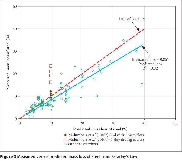
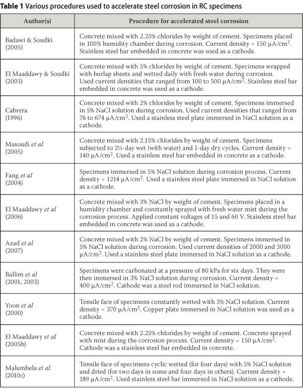
Figure 3 shows a plot of mass loss of steel measured at the end of corrosion tests with predicted mass loss of steel from Faraday's Law. The data in Figure 3 was obtained from various researchers in the literature. A summary of conditions of the experiments used by the researchers are in Table 1. As expected from the variation of conditions for accelerated corrosion from various researchers, Figure 3 shows a large scatter. The difference between mass loss of steel predicted from Faraday's Law and actual mass loss ranged from -6.7 to 23.9% with a mean of 1.3% and a standard deviation of 3.6%. Note that this excludes results from Malumbela et al (2010c) which are also shown in the figure but will be discussed in detail later. Despite the scatter, there was a trend (R2 = 0.82) that measured mass loss was linearly related to predicted loss. It is evident from the figure that at mass losses of steel above 8%, the majority of data points were below the line of equality. This indicates that at large mass losses of steel (>8%), Faraday's Law tends to overestimate the level of steel corrosion. The trend-line shows the predicted loss to be around 18% larger than the measured loss. Some researchers believe this to be caused by corrosion products building up around the reinforcing bar surface and thus forming a physical barrier to the ingress of corrosion agents (Liu & Weyers 1998; Badawi & Soudki 2005). From the previous discussion, it is expected that more soluble products which occupy larger volume will form a large barrier and hence significantly retard the corrosion process.
Despite the trend discussed above, it is worth pointing out that the measured mass loss of steel presented in Figure 3 is an average mass loss of steel over the entire corroded length of a bar. If the level of steel corrosion varies along the bar, average mass loss of steel, and hence Faraday's Law, may underestimate the maximum level of steel corrosion. Rather than measuring average mass loss of steel, some researchers opted to measure maximum pit depths (Torres-Acosta et al 2007; Torres-Acosta & Martinez-Madrid 2003). Torres-Acosta et al (2007) and Torres-Acosta & Martinez-Madrid (2003) tried to correlate maximum pit depths with average penetration depth (calculated from average mass loss). They found them to be linearly related, but maximum pit depth was about eight times larger than average penetration depth. Similar results were found by Rodriguez et al (1997). This is important information which suggests the need to evaluate the accuracy of Faraday's Law to predict maximum mass loss of steel.
Malumbela et al (2010c) researched on the relation between maximum mass loss of steel and Faraday's Law. Their corrosion process involved a current density of 189 μA/ cm2 and two different cycles of wetting of cover concrete with 5% NaCl solution, and natural drying under laboratory conditions. One accelerated process entailed four-day wetting followed by two-day drying cycles whilst in the other, cycles were all four days. They only contaminated the tensile face of RC beams with salt solution. Their target mass loss of steel from Faraday's Law was 10%. This meant 44 wetting days when the current was impressed. At the end of the test, they measured both average mass loss of steel and maximum loss.
It is clear from Figure 3 that for beams with two-day drying cycles, maximum mass losses of steel were largely greater than predicted losses. The largest loss in those beams was 12.1% compared to 10% from Faraday's Law. Despite these larger mass losses of steel, Figure 3 shows that they are still within the range of values that were observed by other researchers who measured average mass loss. However, their consistency, which did not exist in results from other researchers, points to the need to be cautious when predicting maximum mass loss of steel using Faraday's Law.
Mass losses of steel in beams with four-day drying cycles were certainly much larger than corresponding losses in beams with two-day drying cycles. The most obvious reason that can be attributed to beams with longer drying cycles having larger mass losses of steel, is that longer drying cycles could have allowed for more natural corrosion to occur because of the extended time required to reach the desired time of electrolysis. As already mentioned, for beams to have the target level of steel corrosion of 10%, beams corroded using two-day drying cycles were tested for 64 days (44 wetting days + 20 drying days). Beams tested with four-day drying cycles were, however, tested for 80 days (44 wetting days + 36 drying days). This implies that beams under the four-day drying cycle had 16 days of additional natural corrosion compared to beams under the two-day drying cycles. It was later shown by Malumbela et al (2010b) that the natural corrosion rate in beams was too low (30.4 μA/ cm2) to have resulted in the recorded large mass losses of steel in beams with four-day drying cycles. The large differences in mass losses here could be ascribed to the set-up with two-day drying cycles not allowing the complete dryness of the concrete cover at the corroded rebar depth. Therefore, after the drying period, less stable products such as ferrous hydroxide (which according to Figure 2 occupy a larger volume than dryer products) would still be available within the corrosion region. On the other hand, more stable products, such as haematite and magnetite (which occupy less volume) could have formed during the four-day drying periods. The formation of these lesser volumetric compounds could have allowed for more access of corrosion agents to the rebar, which could have led to larger corrosion rates. This notion is in agreement with discussions by Hussain (2010) on the effect of moisture variation on rate of steel corrosion.
Figure 3 clearly indicates that Faraday's Law is not adequate to predict levels of steel corrosion, particularly where sufficient drying of cover concrete is permitted. Since natural steel corrosion often occurs under drier conditions than most accelerated corrosion tests, Faraday's Law is likely to underestimate levels of steel corrosion in in-service structures. It is therefore recommended that further research be carried out to model the interaction between dryness of cover concrete and rate of steel corrosion.
INFLUENCE OF CORROSION TEST ON LOAD-BEARING CAPACITY
Mangat & Elgarf (1999) found that, at mass losses of steel due to steel corrosion up to 7%, the level of current density had little effect on the load-bearing capacity of RC beams. However, at mass losses of 10% and beyond, load-bearing capacity of RC beams decreased significantly with increase in the level of the impressed current density. For example, at a mass loss of steel of 20%, current density of 1000 A/cm2 induced a loss of load-bearing capacity of 60% compared to 78% when a current density of 4000 μA/cm2 was used. They attributed this to a larger loss in the interfacial bond at the steel/concrete interface caused by the high corrosion rates. Contrary to findings by Mangat & Elgarf (1999), Azad et al (2007) reported that it was not the current density that caused a larger reduction in load-bearing capacities at higher levels of steel corrosion, but rather the product of current density with time. They further asserted that a higher value of corrosion current density for a lesser period of time would be as damaging as a lesser value of current density for a longer corrosion period.
Where Mangat & Elgarf (1999) and Azad et al (2007) agreed was that, at large mass losses of steel (>10%), calculated values of load-bearing capacity, using measured average mass losses of steel, had little relation with experimental results. For example, according to Mangat & Elgarf (1999), a mass loss of steel of 19% corresponded to a predicted loss in load-bearing capacity of 20%. The measured loss in the load-bearing capacity was, however, found to be 78%. Azad et al (2007) found average mass loss of steel of 1% to relate to loss in load-bearing capacity of 1.4%. The corresponding relation between mass loss of steel and theoretical load-bearing capacity varied with the level of steel corrosion. At a corrosion level of 31%, theoretical load-bearing capacity exceeded the measured capacity by 30%, but at lower levels of corrosion (around 5%) theoretical capacity was found to be similar to the measured capacity. The researchers (Mangat & Elgarf 1999; Azad et al 2007) attributed the poor predictions of ultimate capacity of beams at high mass losses of steel to losses in the bond between corroded steel bars and the surrounding concrete. They therefore developed necessary correction factors. According to Azad et al (2007), the residual load-bearing capacity of corroded RC beams should be calculated using Equations 1 and 2. In line with their experimental findings, these Equations indicate that the needed-correction-factor, a, reduces with an increase in the level of steel corrosion (it).
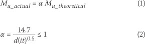
Where
Mu_actual = measured capacity of teams (kN-m)
Mu_theoretical = theoretical capacity of beams based on reduced average cross-sectional area of steel (kN-m)
a = correction factor d = bar diameter (mm)
i = corrosion current density (mA/cm2)
t = duration of corrosion (days)
Torres-Acosta et al (2007) found a poor relation between average penetration depth on steel bars (calculated from average mass loss of steel), due to steel corrosion and the residual capacity of RC specimens. A cross-sectional loss of steel of 1% was found to be equivalent to a loss in capacity of 1.6%. This relation is similar to the relation found by Azad et al (2007) where average mass loss of steel was used. Torres-Acosta et al (2007), however, found a good relation (R2 ~ 1) between the load-bearing capacity and maximum pit depths. From this relation, it can be shown that a 1% maximum loss in area of steel yields a 0.6% loss in load-bearing capacity. Note that Torres-Acosta et al (2007) presented their results using radius loss instead of loss in cross-sectional area of steel. They were converted here to allow them to be compared with those from other researchers. Interestingly, the relation found by TorresAcosta et al (2007) is similar to a theoretical relation between loss of steel cross-sectional area and load-bearing capacity of RC beams developed by Ting & Nowak (1991). Even more intriguing, no correction factors, as recommended by Mangat & Elgarf (1999) and Azad et al (2007) were needed in Ting & Nowak's model. It therefore suggests that the correction factors are limited to theoretical models of load-bearing capacity which use average mass loss of steel. More importantly, it implies that the loss in bond between steel and concrete may not be the reason for the failure of the theoretical models.
Malumbela et al (2010c) showed that load-bearing capacity of corroded RC beams against maximum mass loss of steel was closely related to theoretical results from a basic model of load-bearing capacity of RC beams. This was without applying factors of bond between steel and concrete, as suggested by Azad et al (2007). Malumbela et al (2010c) further demonstrated that the use of average mass loss to predict load-bearing capacity of RC beams at high mass losses of steel will overestimate it.
Results from Torres-Acosta et al (2007) and from Malumbela et al (2010c) against those from Azad et al (2007) and from Mangat & Elgarf (2007) suggest that the load-bearing capacity of corroded RC beams is not related to the level of current density, but to the actual maximum mass loss of steel. However, more test results are needed to confirm this.
CONCLUSIONS
1. This paper discussed various procedures that are often used to accelerate steel corrosion in laboratory tests of RC specimens. It clearly pointed out that, to hurriedly de-passify steel, researchers should avoid adding chlorides to concrete mixes or fully immersing their samples in salt solutions. These procedures result in uniform steel corrosion that unfortunately underestimates the effects of partial surface steel corrosion, which is often observed in in-service structures. It was instead recommended in the paper that limited faces of specimens should be contaminated with chlorides. This can easily be achieved in laboratories by building ponds on surfaces to be contaminated or by selectively spraying them with chlorides.
2. To accelerate steel corrosion, continuous immersing of specimens in salt solution was shown to underestimate the rate of steel corrosion that is observed when corrosion occurs on a drier cover concrete. Since corrosion in in-service structures involves long drying periods, it was recommended that laboratory corrosion tests should also entail long drying periods. Probably more research is needed to standardise the duration of drying periods.
3. Various types of cathodes are often used when accelerating steel corrosion embedded in concrete. Placing cathodes on exterior surfaces of concrete was shown not to represent natural steel corrosion well. It was recommended that cathodes should be placed inside the concrete. Further research on this was, however, recommended.
4. The level of impressed current density to be used to accelerate steel corrosion was found to be contentious between researchers. For example, El Maaddawy & Soudki (2003) and Mangat & Elgarf (1999) found that, at the same level of steel corrosion, higher current densities cause more structural damage than lower densities, while Alonso et al (1998) and Malumbela et al (2010b) found that a lower current density caused more structural damage. It was therefore recommended that this should be researched further.
5. Except for results from Mangat & Elgarf (1999), many researchers found the load-bearing capacity of corroded RC specimens to be related to actual loss in area of steel and not to the level of current density used. Torres-Acosta et al (2007) and Malumbela et al (2010c) further showed that load-bearing capacity of corroded RC beams was related more to maximum mass loss of steel than to average loss. More data to confirm this is, however, needed.
ACKNOWLEDGEMENT
The support of the Concrete Materials & Structural Integrity Research Unit (CoMSIRU) at the University of Cape Town is greatly acknowledged.
REFERENCES
Almusallam, A A, Al-Gahtani, A S, Aziz, A F & Rasheeduzzafar, F 1996. Effect of reinforcement corrosion on bond strength. Construction & Building Materials, 10(2): 123-129. [ Links ]
Alonso, C, Andrade, C, Rodriguez, J & Diez, J M 1998. Factors controlling cracking of concrete affected by reinforcement corrosion. Materials & Structures, 31: 435-441. [ Links ]
Andrade, C & Alonso, C 2001. On-site measurements of corrosion rate of reinforcements. Construction & Building Materials, 15: 141-145. [ Links ]
Azad, A K, Ahmad, S & Azher, S A 2007. Residual strength of corrosion-damaged reinforced concrete beams. ACI Materials Journal, 104(1): 40-47. [ Links ]
Badawi, M & Soudki, K 2005. Control of corrosion-induced damage in reinforced concrete beams using carbon fiber-reinforced polymer laminates. Journal of Composites for Construction, 9(2): 195-201. [ Links ]
Ballim, Y & Reid, J C 2003. Reinforcement corrosion and deflection of RC beams - An experimental critique of current test methods. Cement & Concrete Composites, 25: 625-632. [ Links ]
Ballim, Y, Reid, J C & Kemp, A R 2001. Deflection of RC beams under simultaneous load and steel corrosion. Magazine of Concrete Research, 53(3): 171-181. [ Links ]
Bhargava, K, Ghosh, A K, Mori, Y & Ramanujam, S 2006. Analytical model for time to cover cracking in RC structures due to rebar corrosion. Nuclear Engineering & Design, 23(6):1123-1139. [ Links ]
Broomfield, J. 1997. Corrosion of steel in concrete. London: E & FN Spon. [ Links ]
Cabrera, J G 1996. Deterioration of concrete due to reinforcement steel corrosion. Cement & Concrete Composites, 18: 47-59. [ Links ]
Cairns, J, Du, Y & Law, D 2008. Structural performance of corrosion-damaged concrete beams. Magazine of Concrete Research, 60(5): 359-370. [ Links ]
Castel, A, Vidal, T, Francois, R & Arliguie, G 2003. Influence of steel-concrete interface quality on reinforcement corrosion induced by chlorides. Magazine of Concrete Research, 55(2): 151-159. [ Links ]
El Maaddawy, T, Chahrour, A & Soudki, K 2006. Effect of fiber-reinforced polymer wraps on corrosion activity and concrete cracking in chloride-contaminated concrete cylinders. Journal of Composites for Construction, 10(2): 139-147. [ Links ]
El Maaddawy, T & Soudki, K 2003. Effectiveness of impressed current technique to simulate corrosion of steel reinforcement in concrete. Journal of Materials in Civil Engineering, 15(1): 41-47. [ Links ]
El Maaddawy, T & Soudki, K 2007. Model for prediction of time from corrosion initiation to corrosion cracking. Cement & Concrete Composites, 29(3): 168-175. [ Links ]
El Maaddawy, T, Soudki, K & Topper T 2005a. Analytical model to predict nonlinear flexural behaviour of corroded reinforced concrete beams. ACI Structural Journal, 102(4): 550-559. [ Links ]
El Maaddawy, T, Soudki, K & Topper T 2005b. Long- term performance of corrosion-damaged reinforced concrete beams. ACI Structural Journal, 102(5): 649-656. [ Links ]
Fang, C, Lundgren, K, Chen, L & Chaoying, Z 2004. Corrosion influence of bond in reinforced concrete. Cement & Concrete Research, 34: 2159-2167. [ Links ]
Frangois, R & Arliguie, G 1998. Influence of service cracking on reinforcement steel corrosion. Journal of Materials in Civil Engineering, 10(1): 14-20. [ Links ]
Gadve, S, Mukherjee, A & Malhotra, S N 2009. Corrosion of steel reinforcements embedded in FRP wrapped concrete. Construction & Building Materials, 23: 153-161. [ Links ]
Hussain, R R 2010. Effect of moisture variation on oxygen consumption rate of corroding steel in chloride-contaminated concrete. Cement & Concrete Composites, doi:10.1016/j. cemconcomp.2010.09.014. [ Links ]
Jaffer, S J & Hansson, C M 2009. Chloride-induced corrosion products of steel in cracked-concrete subjected to different loading conditions. Cement & Concrete Research, 39: 116-125. [ Links ]
Jang, B S & Oh, B H 2010. Effects of non-uniform corrosion on the cracking and service life of reinforced concrete structures. Cement & Concrete Research, 40: 1441-1450. [ Links ]
Liu, Y & Weyers, R E 1998. Modelling the time-to-corrosion cracking in chloride-contaminated reinforced concrete structures. ACI Materials Journal, 95(6): 675-681. [ Links ]
Malumbela, G, Alexander, M G & Moyo, P 2010a. Interaction between corrosion crack width and steel loss in RC beams corroded under load. Cement & Concrete Research, 40: 1419-1428. [ Links ]
Malumbela, G, Alexander, M G & Moyo, P 2010b. Serviceability of corrosion-affected RC beams after patch repairs and FRPs under load. Materials & Structures, doi 10.1617/s11527-010-9630-9638. [ Links ]
Malumbela, G, Alexander, M G & Moyo, P 2010c. Variation of steel loss and its effect on flexural capacity of RC beams corroded and repaired under load. Construction & Building Materials, 24: 1051-1059. [ Links ]
Malumbela, G, Alexander, M G & Moyo P 2011. Model for cover cracking of RC beams due to partial surface steel corrosion. Construction & Building Materials, 25: 987-991. [ Links ]
Malumbela, G, Moyo, P & Alexander, M G 2009. Behaviour of RC beams corroded under sustained service loads. Construction & Building Materials, 23: 3346-3351. [ Links ]
Mangat, P S & Elgarf, M S 1999. Flexural strength of concrete beams with corroding reinforcement. ACI Structural Journal, 96(1): 149-158. [ Links ]
Masoudi, S, Soudki, K & Topper T 2005. Post-repair fatigue performance of FRP-repaired corroded RC beams: experimental and analytical investigation. Journal of Composites for Construction, 9(5): 441-449. [ Links ]
Poursaee, A & Hansson, C M 2009. Potential pitfalls in assessing chloride-induced corrosion of steel in concrete. Cement & Concrete Research, 39(5): 391-400. [ Links ]
Rio, O, Andrade, C, Izquierdo, D & Alonso, C 2005. Behaviour of patch-repaired concrete structural elements under increasing static loads to flexural failure. Journal of Materials in Civil Engineering, 17(2): 168-177. [ Links ]
Roberge, P R 1999. Handbook of corrosion engineering. New York: McGraw-Hill. [ Links ]
Rodriguez, J, Ortega, LM & Casal, J 1997. Load carrying capacity of concrete structures with corroded reinforcement. Construction & Building Materials, 11(4): 239-248. [ Links ]
Ting, S & Nowak A S 1991. Effect of reinforcing steel area loss on flexural behaviour of reinforced concrete beams. ACI Structural Journal, 88(3): 309-314. [ Links ]
Torres-Acosta, A A & Martinez-Madrid M 2003. Residual life of corroding reinforced concrete structures in marine environment. Journal of Materials in Civil Engineering, 15(4): 344-353. [ Links ]
Torres-Acosta, A A, Navarro-Gutierrez, S & Teran-Guillen, J 2007. Residual flexure capacity of corroded reinforced concrete beams. Engineering Structures, 29: 1145-1152. [ Links ]
Tuutti, K 1980. Service life of structures with regard to corrosion of embedded steel. In: Performance of concrete in marine environment, ACI SP-65, Detroit, US: American Concrete Institute, pp 223-236. [ Links ]
Vidal, T, Castel, A & François, R 2007. Corrosion process and structural performance of a 17-year-old reinforced concrete beam stored in a chloride environment. Cement & Concrete Research, 37: 1551-1561. [ Links ]
Yoon, S, Wang, K, Weiss, J & Shah S 2000. Interaction between loading, corrosion, and serviceability of reinforced concrete. ACI Materials Journal, 97(6): 637-644. [ Links ]
Yuan, Y & Ji, Y 2009. Modeling corroded section configuration of steel bar in concrete structure. Construction & Building Materials, 23(6): 2461-2466. [ Links ]
Yuan, Y, Ji, Y & Shah, S P 2007. Comparison of two accelerated corrosion techniques for concrete structures. ACI Materials Journal, 104(3): 344-347. [ Links ]
Zhang, R, Castel, A & François, R 2009a. Serviceability limit state criteria based on steel-concrete bond loss for corroded reinforced concrete in chloride environment. Materials & Structures, 42(10): 1407-1421. [ Links ]
Zhang, R, Castel, A & François, R 2009b. The corrosion pattern of reinforcement and its influence on serviceability of reinforced concrete members in chloride environment. Cement & Concrete Research, 39(11): 1077-1086. [ Links ]
Zhang, R, Castel, A & François, R 2010. Concrete cover cracking with reinforcement corrosion of RC beam during chloride-induced corrosion process. Cement & Concrete Research, 40(3): 415-425. [ Links ]
 Contact details:
Department of Civil Engineering
University of Botswana
Private Bag 006'
UB Post, Gaborone
Botswana
T: +267 355 4332
E: malumbela@mopipLub.bw
Contact details:
Department of Civil Engineering
University of Cape Town
Private Bag X3
Rondebosch
7701
South Africa
T: +27 21 650 2592
E: pilate.moyo@uct.ac.za
Contact details:
Department of Civil Engineering
University of Cape Town
Private Bag X3
Rondebosch
7701
South Africa
T: +27 21 650 4012
E: mark.alexander@uct.ac.za

PR0F PILATE MOYO is an Associate Professor lr the Department of Civil Engineering at the University of Cape Town (UCT). He holds a BSc (Eng) from theUniversity of Zimbabwe, an MSc (Eng) from the University of Newcastle upon Tyne, and a PhD from Nanyang Technological University. He is part of the eadershlp of CoMSIRU (Concrete Materials & Structural Integrity Research Unit) at UCT. His research area is structural health monitoring and condition assessment of structures. He regularly acts as a specialist consultant to industry on vibration serviceability problems, dynamic analysis and dynamic based assessment of structures.

DR GOITSEONE MALUMBELA is a Senior Lecturer at the University of Botswana. He graduated with a BSc Honours in Civil Engineering from the University of Missouri Rolla, USA, in 1999, an MSc (Engineering) from the University of the Witwatersrand in 2003 and a PhD from the University of Cape Town in 2010. His research nterests are in the performance of corrodec and repaired reinforced concrete structures.

PROF MARKALEXANDER Is Professor of CM Engineering at the University of Cape Town (UCT). He holds BSc (Eng), MSc (Eng), and PhD degrees from the University of the Witwatersrand, Johannesburg. His teaching and research interests are in cement and concrete materials engineering. He is part of the eadershipofthe UCT CoMSIRU (Concrete Materials & Structural Integrity Research Unit) and is currently the President of RILEM. He acts as a specialist consultant to industry and the profession on concrete materials problems. He is a Fellow of the South African Institution of Civil Engineering, the South African Academy of Engineers, and the University of Cape Town.

