


Serviços Personalizados
Artigo
 Inglês (pdf)
 Artigo em XML
 Referências do artigo
Indicadores

Links relacionados
-
 Citado por Google
 -
 Similares em Google
Compartilhar

 Permalink
Journal of the South African Institution of Civil Engineering
versão On-line ISSN 2309-8775
versão impressa ISSN 1021-2019
J. S. Afr. Inst. Civ. Eng. vol.54 no.1 Midrand Abr. 2012
TECHNICAL PAPER
A rational approach to predicting the buckling length of compression chords in prefabricated timber truss roof structures braced by means of diagonal bracing
W M G Burdzik; N W Dekker
ABSTRACT
In South Africa, timber-trussed roofs supporting concrete tiles have for many years often been braced solely by means of diagonal braces. Failures have shown that the diagonal brace was inadequate for larger span roofs, and the use of diagonal bracing has subsequently been limited to spans of less or equal to 10 m. When designing the compression chords of a timber truss in a braced roof, SANS 10163:1 (2003) recommends a minimum effective length for out-of-plane buckling of not less than 15 x b, which is 540 mm for a 36 mm wide member. This effective or out-of-plane buckling length of the top chord was later assumed to be equal to the spacing of the trusses. With the availability of PC-based packages that are able to perform three-dimensional buckling analyses, it is perhaps useful to investigate the validity of using the effective length equal to the truss spacing, and then also the 10 m limit on span for roofs braced by means of diagonal braces.
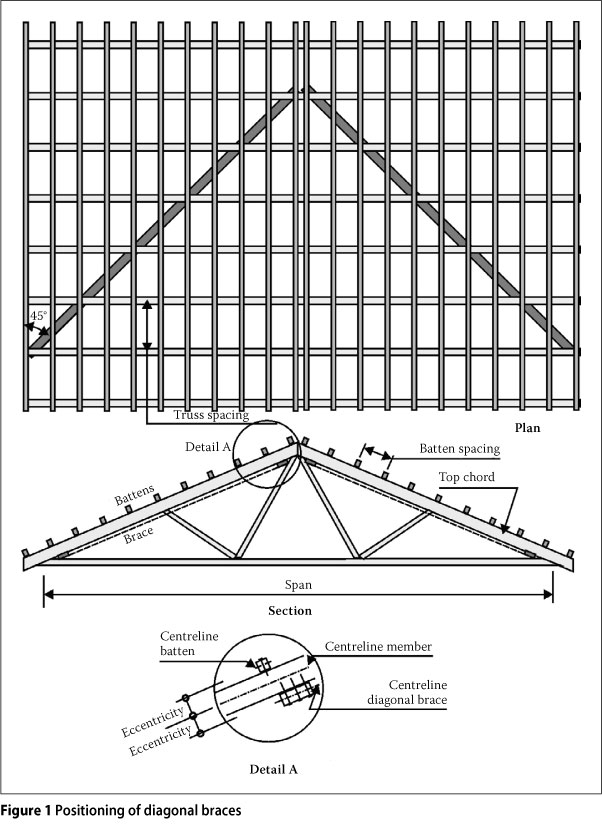
A common error made when analysing three-dimensional buckling problems is to assume connectivity on the centreline of the members, thereby neglecting eccentricity between the centreline of the bracing and the centreline of the member being braced (see Figure 1). In timber-trussed roofs, the diagonal brace is nailed to the underside of the top chord of a number of adjacent trusses. The brace runs at more or less 45° and triangulation appears to be complete when viewed on plan, as the battens form the other elements of the bracing system triangulation. Trusses some distance from the trusses that are connected to the diagonal brace can, however, only obtain lateral support via the battens that are connected to the top of the compression chords. The authors feel that a more correct way of analysing a timber-trussed roof, braced by means of a diagonal brace, requires that the eccentricity between the centreline of the battens on top of the compression chords and the centreline of the braced points on the underside of the compression chords be taken into account. Furthermore, the connections between the battens and the top chord are not infinitely stiff and this stiffness, together with the low torsional rigidity of the timber members, should be taken into account in the buckling analysis. The analysis can be further improved by taking the out-of-plane bending stiffness of the web members into account. All these factors will influence the buckling length of the compression chords to some degree.
In this paper, the authors show how incorrect assumptions may mislead the designer into believing that the buckling length is equal to or less than the spacing of the trusses. They also show that, even though the bracing members have been placed on the correct sides of the top chord in the analysis, incorrect assumptions about the torsional stiffness of the top chords can lead to buckling lengths that are slightly less than when a more realistic torsional stiffness is used.
Keywords: effective length, buckling, flexible supports, bracing
INTRODUCTION
Since the introduction of computer-based analysis programs for timber roofs, the pre-and post-processing parts of the software have changed and improved to the extent that the designer is no longer aware of the design process, even though forces, displace-ments, sizes and assumed effective lengths may be printed for checking by a competent person. Loads are calculated from the layout and these are applied to a two-dimensional analysis of the truss, even though a timber roof structure is a three-dimensional problem constructed out of a brittle material with limited ductility in the connections. Limited ductility can be a problem in cases where construction errors have been made and force-fitting is applied. Assumptions are made about the member sizes and sometimes the connector plate stiffness for an initial analysis. More often than not, a centreline analysis using beam elements is used and the forces so obtained are used to size the members in accordance with SANS 10163: Part 1 (2003) or Part 2 (2001). At this stage of the design, assumptions are made about the type of bracing to be used, as well as the effective or buckling length of the compression chord that would result from using that specific type of bracing. In most cases the trusses are re-analysed with the correct sizes once these have been calculated to ensure that the sizing is adequate for the load and that the deflection is not excessive.
SANS 10163: Part 2 (2001) has a rule of thumb for the minimum slenderness, Le/b, equal to 15 for tiled roofs or the spacing of the purlin for sheeted roofs. Many believed, and some still believe, that the effective or buckling length of the top chord is equal to the spacing of the battens. This assumption would perhaps be correct if the tiles could be relied on to supply diaphragm action, and that the battens were rigidly connected to the compression member. In such a case, any further bracing would only be required for erection purposes. The authors accept that diaphragm bracing by the tiles will initially be active, but with time the friction between the tiles seems to break and movement does occur. This eventual movement of the tiles has led to failures of roofs.
The assumption of the buckling length equal to 15 x b, with b = 36 mm, may not be a problem when the spacing of the trusses is equal to 640 mm as is commonly used in Australia, but could become a problem where the spacing of the trusses is as much as 1 050 mm, as is often found in South Africa. The minimum slenderness of Le/b = 15 was later changed by the South African Institute for Timber Construction to an in-house rule which suggests, the operative word being suggests, an effective buckling length of the spacing of the trusses, i.e. 750 mm to 1 050 mm. The authors believe that a blanket rule such as effective length = 15 x b or even buckling length equal to the spacing of the trusses may not be conservative, as the buckling length depends on the boundary conditions, the stiffness of the bracing and the method of transferring loads once buckling is initiated.
For small span timber trusses, i.e. up to 10 m, a diagonal brace is the norm in South Africa. As the limit on the span for the use of a diagonal brace is less than 10 m, only the 10 m span and 7.5 m spans were investigated. Timber sizes for 10 m span roofs would typically be 36 mm x 111 mm top and bottom chords with 36 mm x 73 mm web members. When bracing a 10 m span trussed roof, a 36 mm x 111 mm timber member is fixed to the underside of the compression chords and runs at about 45° when seen in plan. Three 100 mm long nails are used to fix the brace to the underside of the top chord (see Figure 1). Maximum spacing rules are used to ensure that trusses are not too far from the brace. Battens, the smallest nominally being 36 mm x 36 mm, are placed on top of the compression chord and these are then fixed with one 75 mm long nail to the compression chord.
In this paper it is the intention of the authors to only investigate diagonal bracing, and not all forms of bracing that are currently used by the South African timber roof truss industry. Although this investigation is a theoretical exercise and cannot, at this stage, be validated by test results, the authors are of the opinion that a three-dimensional buckling analysis is an acceptable way of determining the buckling length of a compression chord in a timber roof structure. Buckling and finite element analyses are widely used for many structural systems and materials as the analyses are based on theories that have historically been proven to work for structures.
EFFECTIVE LENGTH FACTORS IN SIMPLE LATTICE STRUCTURES
In-plane and out-of-plane buckling
The effective length factor, or K- factor, is used to adjust the actual unrestrained length of a compression member to account for prevailing boundary conditions. Many software packages use a default out-of-plane effective length factor of 0.85, implying some form of rotational joint restraint by adjacent members. This is only possible where adjacent members have high out-of-plane bending or torsional stiffness and they themselves are not compression members that could buckle. Some design codes specify effective length factors for compression members in lattice trusses. BS 5400 Part 3 (BSI 2000), in its Table 11, specifies effective length factors for buckling in the plane of the truss, as well as out of the plane of the truss. In all cases the values given in Table 11 of BS 5400 Part 3 (BSI 2000) are less than or equal to 0.85. Eurocode 5 (CEN 1995) gives the effective column length for members of triangulated trusses with loading at the nodes as the bay length. For strength verification, Eurocode 5 (CEN 1995) states that the calculated force should be increased by 10%.
SANS 10163 Part 1 (2003) has non-mandatory clauses for the calculation of the effective length factor:
1. With regard to the effective length for "in-plane" buckling, in a continuous compression member such as a chord of a truss, take the effective length for "in-plane" buckling as the distance between the node points multiplied by a factor of between 0.85 and 1.0, dependingon the degree of fixity and the distribution of the load. In a non-continuous compression member such as the web of a truss, take the effective length for "in-plane" buckling as the actual length of the member multiplied by a factor of between 0.85 and 1.0, depending on the degree of end fixity.
2. With regard to effective length for "out-of-plane" buckling, thefollowing apply:
a) take the effective length of the compression chords to be equal to the purlin or batten spacing, provided that the purlins or battens are adequately fixed to the chords, properly spliced to transmit the forces and adequately braced against longitudinal movement;
b) in the case of tiles supported on bat-tens, the battens being spaced less than 400 mm apart andfixed to the chords with one or two plain wire nails, use a minimum slenderness value of Le/b = 15for calculating the ultimate compressive stresses for the chords;
c) if the compression chords are braced by means of a bracing frame or a truss that restrains the longitudinal movement of all battens, use the minimum slenderness value given in (b) above; and
d) in the case of web members, use the distance between the intersection of the centrelines of connecting members.
Boundary conditions influencing the degree of restraint exercised on a compression member, are not merely a function of connection details and continuity, but are influenced by the capacity of adjacent members at the node. Consider the example of a simple lattice truss with a constant section, shown in Figure 2, where lateral supports are provided at nodes, A, B, C, D, E, F and G:
The compression chord ABCDEFG is divided into equal portions. The basic principle that the buckling load for member ABCDEFG is unique shows that an effective length factor of less than one for a particular member is consistent with an effective length factor of greater than one in the adjacent members, albeit with a smaller force, as shown in Equation 1:

If the member is of constant section with a constant force, Equation 1 will be satisfied if the buckling length is taken as L = Lab = LBC = Lcd. If the torsional stiffness of the lacing elements is ignored, an effective length factor of less than one is clearly incorrect. For the loading as shown, the force in ABCDEF will vary over the length of the truss. Once again, the buckling strength of the chord ABCDEF is unique. In order to still satisfy Equation 1, the effective length factors for the members with the lower forces are greater than for those members with the higher forces.
It is significant that the Eurocodes for steel design specifically have discarded the practice of using tabulated effective length factors in the design of both compression and flexural members. Elastic buckling loads are used as a basis of design, and such loads are commonly calculated using computer programs.
Stanway, Chapman & Dowling (1992) have discussed the influence of elastic supports at any position of the length of the strut, thereby considering the influence of unequal bay lengths and the beneficial restraint offered by adjacent subcritical elements having a shorter buckling length. The basis of elastic buckling analysis is subsequently discussed.
Most PC-based analysis packages are capable of performing buckling analyses on framed structures using beam elements, and individual members using shell elements. It is important that the user be aware of the actual process and the premises on which such analyses are based. The method of buckling analysis of a frame structure is presented in Coates et al (1988), as described below.
In the case of a linear elastic analysis of a framed structure, deformation is linearly related to load, or, expressed in matrix form:

where:
P is the force or load matrix,
λ is the displacement matrix,
Ks is the stiffness matrix.
The terms of Ks are constant for a given structure, provided that second order effects are neglected, therefore Ks is independent of P. If, however, the influence of axial forces on member stiffness is included, Ks becomes a function of P, or Ks = Ks(P).
In the case where axial loads are not neglected, Equation 2 becomes non-linear, but if the axial loads are known, the deflections may be calculated.

In Equation 3 the term X has been inserted as a load multiplier. As the loads are progressively increased, a state of neutral equilibrium is achieved where any deflection is possible for a given load level. This state defines instability and may be referred to as λ= λcr. The critical state is consistent with the matrix Ks(λP) becoming singular.
A test of the singularity of the matrix Ks can therefore be used as a check on stability. If it is non-singular and positive definite, the structure is stable; if it is singular, the structure is on the point of collapse. The value of Xcr is therefore a multiple whereby an arbitrarily chosen load can be multiplied to achieve a state of collapse. The following comments regarding the value of λcr should be clearly noted:
■ λcr is not a safety factor. Even if P is chosen to represent load effects at working loads, the influence of inelastic buckling is not taken into account in an elastic buckling analysis.
■ In the case where buckling modes are de-coupled, for example lattice structures consisting of pin-ended members, the value of λcr applies to the member most susceptible to buckling, and has no application to other members.
■ If a two-dimensional analysis were to be carried out to determine λcr, the value of λcr applies to in-plane and not out-of-plane buckling.
The significance of an elastic buckling analysis is that the value of λcrP is the elastic buckling load of the critical member or portion of a structure, or of the structure as a whole. Dekker and Burdzik (2000) have shown that, in order to calculate the inelastic buckling load, and therefore the factored resistance of the critical member, Cr, the following procedure may be followed:
Calculate the equivalent effective unbraced length from the relationship:
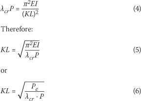
where:
Pe = Euler buckling load for a compression member hinged at both end
P = applied load
K = effective un-braced length factor
Calculate the compressive resistance Cr using the value of KL obtained from Equation 5 for the appropriate member size. The resistance equation is given by SANS 10163:1 (2003):
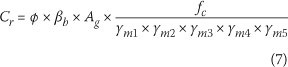
The appropriate slenderness ratio is given in SANS 10163:1 (2003)
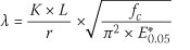
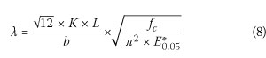
or for a rectangular section
and the buckling factor, βb is given by:

with n = 1.8 and
where:
E0.05= fifth percentile modulus of elasticity for members working in isolation.
KxL = effective length or buckling length
r = radius of gyration, 
fc = compressive stress parallel to the grain.
STIFFNESS OF CONNECTORS
When a stiffness matrix method with beam elements is used to analyse a structure, there are a number of ways of modelling the connection between, for instance, the batten and the top chord. One of the methods is the use of a spring as a connector. This, however, does not adequately address the possible rotation of the top chord, as the chord, the spring and the batten are in the same plane. Rotation of the chord will then 'soften' the stiffness of the connection. If a beam element analysis is applied to the three-dimensional model, the authors are of the opinion that it is better to model the nail with an element that has the same bending stiffness as the transverse stiffness of the nail in double curvature, than to use a spring. The spring will not have the necessary eccentricity to allow the torsional displacement of the chord.
Eurocode 5 (1995) allows a method whereby the long-term stiffness of nails, that connect two pieces of timber together, may be calculated. The long-term stiffness of a nail without pre-drilling is given by:
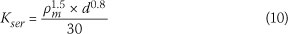
where:
Kser = connector stiffness in kN/m
pm = average density of the timber in kg/m3
d = diameter of the nail in mm.
This equation has been found, by a number of tests performed at the University of Pretoria, to represent the stiffness of nails in South African pine fairly well.
Using the Eurocode 5 (CEN 1995) equation for long-term nail stiffness, the stiffness of a connection using a 3.2 mm nail in timber with an average density of 450 kg/m3 can be calculated and a value of 807 kN/m is obtained. A stiffness for the nailed connection of 800 kN/m was used in all the analyses. Typical trusses that are braced by a diagonal brace are usually spaced at about 750 mm, will have a top and chord with a depth of 111 mm, webs with a depth of 73 mm and battens with a depth of 36 mm. The distance between the centrelines of the top chord and the batten is then = 73.5 mm. It would not be out of place to assume that the nail is initially placed in double flexure, as this is the most likely form of failure for a thin timber-to-timber dowel-type connector (Eurocode 5, i.e. CEN 1995). Basic slope deflection equations (Coates et al 1988) allow one to determine the flexural stiffness of a member in double curvature that has the same stiffness as the nail. See Figure 3 for forces involved.
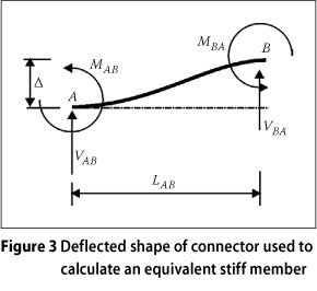
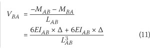
But Vab/A is equal to the stiffness of the nail, Kser'
The required flexural stiffness EI can be calculated as follows:
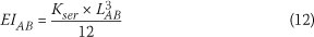
The equivalent diameter of a steel nail that now connects the batten to the top chord can be determined from this equation. If the modulus of elasticity of the steel is 206 GPa and Equation 12 is applied:
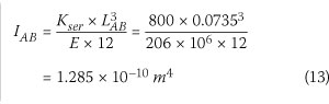
The diameter of the equivalent round nail with the required second moment of area is 7.2 mm. It may be prudent to remember that the theoretical stiffness of the nails is based on tests where the nail is forced into double curvature by longitudinal displacement of the connected members. However, if the chord is free to rotate, this stiffness will be reduced, i.e. 'soften', and it would no longer be correct to assume a spring stiffness of 800 kN/m when using springs in the analyses. It would be more correct in the authors' opinion to have a stiffness of something between fully fixed on both ends and a cantilever. For a cantilever the stiffness is a quarter of that of a fully fixed member, i.e. 200 kN/m.
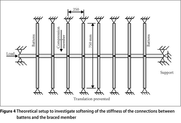
As an illustration of how the connection 'softens' with relative rotation between two connected members, two analyses were undertaken. A 3.75 m long, 36 mm x 225 mm, grade 5 timber, modulus of elasticity = 7 800 MPa, with 36 mm x 36 mm, grade 4 battens spaced at 250 mm with the battens having a length of 750 mm, was subjected to unit axial loading (see Figure 4). In the first analysis, the eccentricity between the centreline of the battens and the compression element was taken into account, with the nails being modelled by bending elements. No account was taken of the possible lower shear modulus of the compression member. A buckling load factor of 174 and an out-of-plane buckling length of 622 mm resulted.
In the second analysis, the member was analysed using shell elements with springs connecting it to the battens. The spring stiffness was reduced until the same buckling factor, i.e. 174, was obtained as in the first analysis. The spring stiffness that was required to achieve this was 267 kN/m and no longer 800 kN/m. This shows that, when using shell or plate elements that are connected to the bracing battens by way of springs, great care should be taken as it may result in misleading answers. If the spring stiffness of 800 kN/m is used, the buckling load factor, X, was 293 with a buckling length of 480 mm. Both the buckling lengths are substantially greater than the spacing of the battens.
It is perhaps of interest to note that when this technique is used to determine the buckling length of a 2.1 m long, 36 mm x 111 mm, Grade 5 SA pine member that is braced by means of 750 mm long, 36 mm x 36 mm Grade 5 battens, spaced at 300 mm, a buckling length of 454 mm results. If the member length is increased to 3.0 m with the battens still at 300 mm spacing, the buckling length decreases slightly to 446 mm. This may explain why a minimum slenderness of 15 x b was written into SANS 10163: Part 2 (2001), as that particular clause was based on work done by Pienaar (1984) who tested 36 mm x 111 mm compression members that were braced by battens nailed to one side.
SHEAR MODULUS
It is accepted that the shear modulus of South African pine is about equal to MOE/13 (Burdzik & Nkwera 2003). Not all software packages have the facility to input the shear modulus. Prokon (2011), the package used in the following analyses uses a Poisson Ratio, v, of 0.2. The shear modulus is then calculated from the following equation:
This shortcoming can be overcome by reducing the St Venant torsional constant of the relevant members by 13/2.4 = 5.42.
ANALYSES
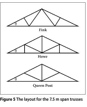
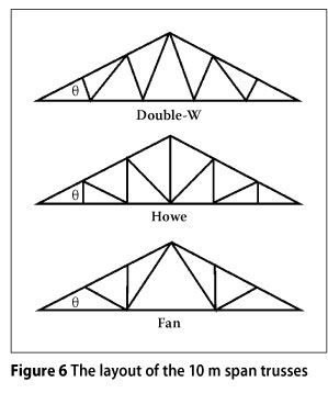
In order to demonstrate the principles discussed above, a commonly available PC-based analysis package, Prokon (2011), was used to calculate the effective length factors of the top chord of gable to gable timber-trussed roofs with spans of 7.5 m and 10 m, with pitches of 17.5°, 25° and 35°. The batten spacing was taken as 262 mm and 305 mm respectively in order to simplify the input of the truss and batten geometry. Only the tile weight and the self weight of the timber were used to determine the buckling length of the top chords, as the buckling is a long-term problem, rather than a problem that occurs when imposed load is applied, as imposed load will increase the friction between the tiles, leading to bracing by diaphragm action. Tile mass was taken as being 55 kg/m2, although the actual mass is not that important, as the buckling analysis is only used to calculate buckling lengths. The different configurations (see Figures 5 and 6) were used to ascertain whether the configuration would play a significant part in the buckling length of the compression chord.
Results of the analyses
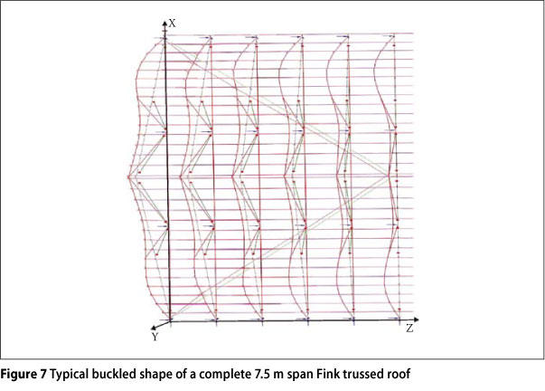
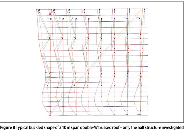
In all cases the top and bottom chords were assumed to have dimensions of 36 mm x 111 mm with web members being 36 mm x 73 mm with a 36 mm x 111 mm diagonal brace, although in practice the top and bottom chords may be 36 mm x 73 mm and the diagonal bracing member a 36 mm x 73 mm for small span roofs. A full span, complete roof (see Figure 7) was analysed to ascertain the buckled shape of the roof so that a half-structure, with the correct boundary conditions, could be analysed. From the buckled shape, one can deduce that the apex moves as the brace is flexible and it then becomes apparent that one cannot assume an inflection point at the apex. This then makes it possible to define the boundary conditions for a structure where only the half structure is investigated. If the half structure with the correct boundary conditions is used, it simplifies the input and speeds up the analyses of the various truss layouts and spans. Assume that the truss lies in the X-Y plane and that the Z axis is perpendicular to that plane. The eaves of the truss is supported in Y and Z directions, whereas the apex and the bottom chord of the half truss are supported in the X direction and fixed against rotation about the Y axis. Figure 8 shows the buckled shape of the half-structure with a span of 10 m.
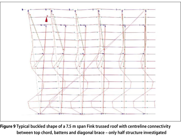
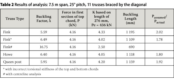
It is noteworthy to see how the top chords of the trusses will buckle, as this buckling shape is sometimes visible on the tile lines of some of the older houses in South Africa. The battens force sympathetic buckling, i.e. all top chords move in the same direction, as all the top chords are tied together by the battens. It is also apparent from the buckled shape that the low torsional rigidity of the top chord and the stiffness of the nails all play a part in the final buckled shape. A buckling analysis of a trussed roof, where centreline connectivity of chords, battens and diagonal brace is assumed, is shown in Figure 9. Note the difference in the buckled shape of the roof shown in Figure 8, where the actual relative position of the members is taken into account, and Figures 9, where centreline connectivity is assumed. The effect of the difference in the buckled shape leads to a difference in the buckling length of the top chord as is given in Table 2.
This difference in the buckled shape and the buckling load factor between centreline connectivity and the buckled shape of the trussed roof where the relative distances between the centreline of the battens, top chord and diagonal brace are taken into account, shows how important it is to take the actual position into account. Even if one allows for the stiffness of the nails in the centreline analysis, one may still land up with what the authors believe to be an incorrect evaluation of the buckling length of the top chord.
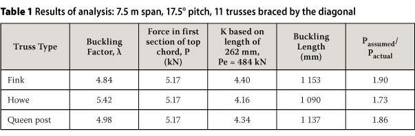
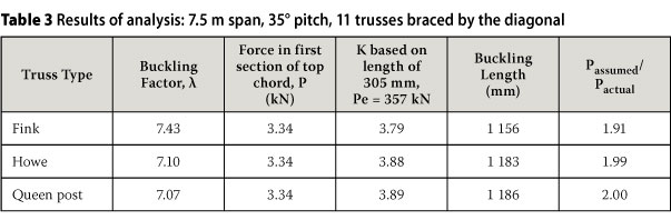
The results of the analysis for the different configurations of the 7.5 m span trusses are given in tabular form in Tables 1, 2 and 3.
By considering the results shown in Tables 1 to 3 it is clear that the actual buckling length exceeds the purlin spacing by a factor of between 3.8 and 4.4. The error caused by centreline modelling is shown to be significant in Table 2. No further centreline modelling was undertaken as the authors were convinced that the difference in the buckling factors for the different layouts would not be significant.
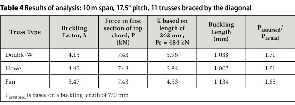
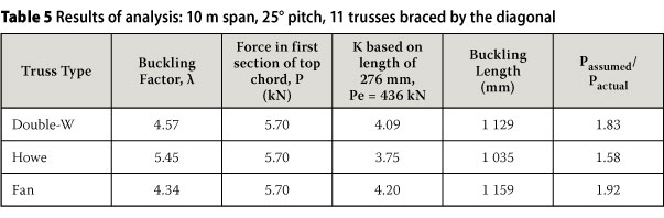
The results of the analysis for the different configurations of the 10.0 m span trusses are given in tabular form in Tables 4, 5 and 6.
ULTIMATE STRENGTH OF TRUSSES
To see whether the theoretical increased buckling length will negatively influence the design of timber trusses, one each of the 7.5 m and 10 m trusses will be used to illustrate the code requirements between using the effective buckling length based on the truss spacing, and the theoretical buckling length of 1.2 m.
Fink truss layout at 7.5 m span with 25° pitch
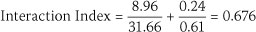
If one includes the imposed load, the imposed load on a tributary area of 5.63 m2 is 0.46 kN/m2. A frame analysis on the truss with pin joints between the web members and the chords, but with continuity of the top and bottom chords, was applied. With a total load that includes all self-weight and imposed load, the ultimate axial force in the top chord = 8.96 kN and the ultimate moment in the chord = 0.24 kN.m.
The axial resistance using a buckling length of 750 mm can be calculated from Equation 8:
and the buckling factor β is given by Equation 9:
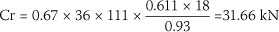
The resistance of a 36 mm x 111 mm Grade 5 member is therefore (Equation 7):
Resistance 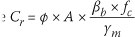
Ym1 = 0.60 + 0.63 wDS = 0.6 + 0.63 x 0.54 = 0.94
Ym3 = 0.82 + 0.023 L = 0.82 + 0.023 x 7.5 = 0.993 for 7.5 m span
The product of the y factors is equal to 0.93.
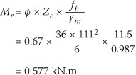
The moment of resistance,
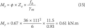
The interaction equation, i.e. Interaction Index:
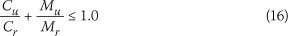
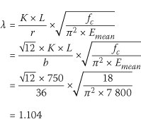
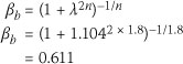
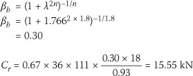
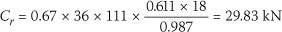
Using a buckling length of 1.20 m the slen-derness and the buckling factor are:
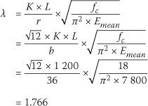
and the buckling factor βb is given by:
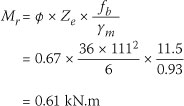
The moment of resistance,
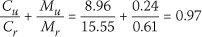
The Interaction Index:
In both cases the interaction equation is satisfied and the truss satisfies the requirements of SANS 10163: Part1 (2003).
Double-W truss layout at 10 m span
If one includes the imposed load, the imposed load on a tributary area of 7.5 m2 is 0.425 kN/m2. With a total load that includes all self-weight and imposed load, the ultimate force and bending moment in the top chord was found to be Cu = 13.24 kN and Mu = 0.23 kN.m.
Ym1 = 0.60 + 0.63 wDS = 0.6 + 0.63 x 0.54 = 0.94
Ym3 = 0.82 + 0.023 L = 0.82 + 0.023 x 10.0 = 1.05 for 10 m span
The product of the ym factors = 0.987
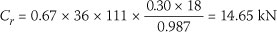
With an assumed buckling length of 0.75 m and an assumed top chord size of 36 mm x 111 mm in a Grade 5 timber, the resistances become:
The moment of resistance,
The interaction equation:
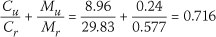
Whereas, if a theoretical buckling length of 1.2 m is used:
The Interaction Index:
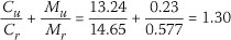
The interaction equation indicates that the 36 mm x 111 mm, Grade 5 SA pine member fails the interaction equation with the increased buckling length of 1.2 m. As the imposed load would increase the friction between the tiles, the buckling length would be substantially reduced. The increase of the interaction equation to 1.3 would not, in the opinion of the authors, increase the probability of failure substantially. It is therefore not surprising that very few failures of timber trussed roofs of spans less than 10 m that are braced by means of a diagonal brace, have been noted.
CONCLUSION
The theoretical buckling lengths of the compression chords, of trusses in a roof braced by means of a diagonal brace, are shown to be in the region of between 1 m and 1.2 m for a gable-to-gable timber roof structure. This increase in the buckling length from 0.76 m to over 1.0 m may not be critical for roofs that have been designed for a buckling length of 0.76 m, or the spacing of the trusses, as the imposed load is very seldom applied to the full roof. Furthermore, the imposed load would increase the friction between the tiles, thereby perhaps leading to diaphragm bracing. The 30% shortfall in capacity should not impact significantly on the probability of failure of the compression chords, provided that the integrity of the connections between the trusses and the battens is maintained.
Ignoring the lack of torsional stiffness of the top chord also has a small effect on the buckling length obtained from the analysis. This may not be true for sections that have a greater depth, i.e. depth of 149 mm and 225 mm. However, a centreline analysis neglecting to consider the distance between the centrelines of the brace, the chords and the battens is shown to under-estimate the theoretical buckling length by a dangerous margin, possibly leading to unsafe member sizes.
The buckling analyses and calculations would appear to justify limiting the span of trusses that are braced by means of a diagonal brace to less than 10 m, as the capacity of the nailed connections between the battens and the braced trusses may be exceeded once buckling is initiated. Owing to the many uncertainties involved, as well as the number of failures noted, it is proposed that the buckling length should be increased to 1.2 m or 30 x b for timber-trussed roofs that are braced solely by means of diagonal bracing. Perhaps there should be two interaction equations for checking the lateral buckling strength of the roof trusses. The first check should be to ascertain whether the truss strength is adequate for permanent load with the increased buckling length, and the second for total load, with the buckling length, however, reduced to 15 x b.
REFERENCES
BSI (British Standards Institution) 2000. BS5400 Part 3. Steel, concrete and composite bridges. Code of practice for design of steel bridges. Milton Keynes, UK: BSI. [ Links ]
Burdzik, W M G & Nkwera, P D 2003. The relationship between torsional rigidity and bending strength characteristics of SA pine. Southern African Forestry Journal, 198: 17-21. [ Links ]
Coates R C, Coutie M G & Kong F K 1994. Structural Analysis, 3rd ed., London, UK: Chapman & Hall. [ Links ]
Dekker, N W & Burdzik, W M G 2000. A rational approach to the design of bracing to resist stability forces and a review of the CSA S16.1-99 proposal. Journal of the South African Institution of Civil Engineering, 42(1): 2-6. [ Links ]
CEN (European Committee for Standardization) 1995. Eurocode 5. Design of timber structures. Part 1: General rules and rules for buildings. NVN-ENV 1995-1-1. Brussels, Belgium: CEN. [ Links ]
Pienaar F R P 1984. The effective length of timber rafters in compression. Special Report HOUT 348, Pretoria: CSIR National Timber Research Institute. [ Links ]
PROKON Software Consultants Ltd 2011. PROKON suite of structural analysis programs. Pretoria: PROKON. [ Links ]
SANS 2001. SANS 10163-2:2001: The structural use of timber. Part 2: Allowable stress design. Pretoria: South African Bureau of Standards. [ Links ]
SANS 2003. SANS 10163-1:2003: The structural use of timber. Part 1: Limit-states design. Pretoria: South African Bureau of Standards. [ Links ]
Stanway G S, Chapman J C & Dowling P J. 1992. A simply supported imperfect column with a transverse elastic restraint at any position. Proceedings of the Institution of Civil Engineers - Structures & Buildings, 94: 205-206. [ Links ]
 Contact details:
Department of Civil Engineering
University of Pretoria
Pretoria 0002 South Africa
T: 012 420 2746
F: 012 362 5218
E: walter.burdzik@up.ac.za
Contact details:
Department of Civil Engineering
University of Pretoria
Pretoria 0002 South Africa
T: 012 420 2179
F: 012 362 5218
E: nick.dekker@up.ac.za

PROF WALTER BURDZIK is Professor in the Department of Civil Engineering at the University of Pretoria. He received his degrees from the university of Pretoria and has been involved in timber research and structural timber design for the last 25 years. He runs one of the few recognised timber-testing facilities in South Africa and is often involved in gueries surrounding the importing of structural timber and wood-based products. Because of his timber and timber products testing background he felt it necessary to serve on all the SANS committees charged with writing the South African timber design codes and specifications that have to do with wood-based structural products. He is also involved in the testing of new building systems for Agrément SA. His fields of interest also include steel, concrete and masonry design.

PROF NICK DEKKER received the degrees of BSc Eng, B Eng Hons and M Eng from the university of Pretoria, and a Ph D from the university of the Witwatersrand. He spent most of his professional career with BKS where he was responsible for the design of a wide range of structures, including bridges, industrial and commercial buildings, shopping centres, sports centres and process buildings. in 1996 he co-founded the consulting practice Dekker & Gelderblom, and was appointed as a Professor of Structural Engineering at the university of Pretoria. He received an NRF (National Research Foundation) rating in 1997. His field of interests include structural design in steel, pre-stressed concrete and reinforced concrete.

