


Servicios Personalizados
Articulo
 Inglés (pdf)
 Articulo en XML
 Referencias del artículo
Indicadores

Links relacionados
-
 Citado por Google
 -
 Similares en Google
Compartir

 Permalink
Journal of the South African Institution of Civil Engineering
versión On-line ISSN 2309-8775
versión impresa ISSN 1021-2019
J. S. Afr. Inst. Civ. Eng. vol.54 no.1 Midrand abr. 2012
TECHNICAL PAPER
Weak interlayers in flexible and semi-flexible road pavements: Part 1
F Netterberg; M de Beer
ABSTRACT
Weak layers, interlayers, laminations and/or interfaces in the upper structural layers of road pavements are specifically prohibited in most road-building specifications. However, such layers are extremely common and often lead to premature pavement distress. In Part 1 of this two-part set of papers, it is shown that from experience with heavy vehicle simulator (HVS) and dynamic cone penetrometer (DCP) testing, the presence of such layers and/or conditions at any depth in the structural layers of a flexible or semi-flexible pavement is far more deleterious than is commonly appreciated. In Part 2 the effects of these weak layers are further modelled and discussed using various examples based an HVS testing and mechanistic pavement analyses. In particular, a weak upper base course of a cemented pavement under a thin bituminous surfacing may lead to severe surfacing (and upper base) failure within a matter of weeks to months after opening to traffic, not excluding failure even during construction. In this paper (Part 1), the causes of weak layers, interlayers, laminations and/or interfaces, together with simple methods for their detection during construction and analyses of their effects on the structural capacity of flexible and semi-rigid (cemented) road pavements, are briefly discussed.
Key words: weak layers, interlayers, detection, pavement, stabilised
INTRODUCTION
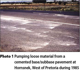
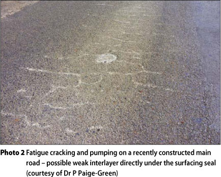
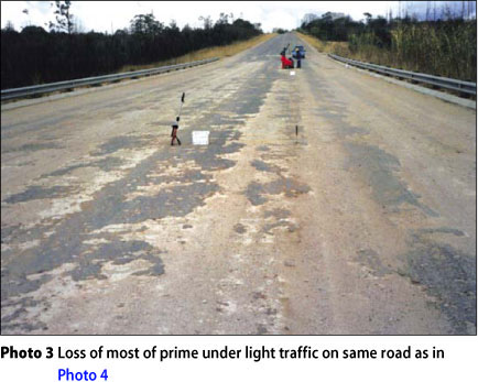
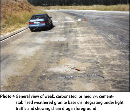
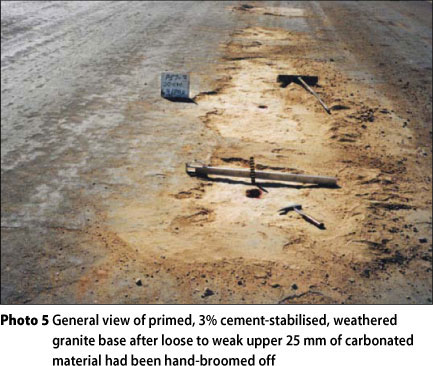
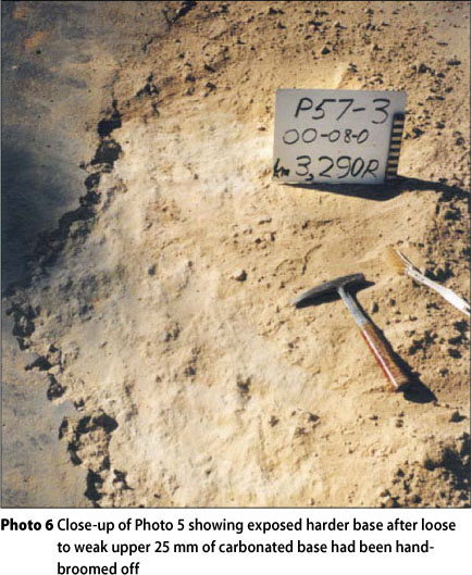
Premature distress in the form of rippling, arcuate (curved) slippage cracking or shoving of the surfacing and shallow base failures of pavements with bituminous surfacings is not rare in southern Africa. The authors know of over 100 such cases that have occurred over the last 50 years and have investigated a number of them. Such distress is usually due to the presence of a weak interlayer between the bituminous surfacing and the base course. Weak interlayers are in fact quite common in spite of current precautions specified to prevent them. Pumping of fines through cracks from a weak interlayer (or laminated interface) between a concrete, asphalt or cemented base and the subbase (De Beer 1985) is another well-known form of distress. Photo 1 shows pumping from a cracked cemented base layer, and Photo 2 shows some fatigue cracking and pumping from a recently constructed road. Examples of delamination (possibly due to construction) are shown in Photos 3, 4, 5 and 6.
The aim of this paper (Part 1) is to show by means of case histories, HVS and DCP testing that the presence of weak layers, interlayers, laminations and/or interfaces at any depth in the structural layers (but especially the upper base) of a flexible or semi-flexible pavement are far more deleterious than is generally assumed or appreciated. In Part 2 of this two-part set of papers (De Beer et al 2012 - see page 43 of this edition) this effect is further discussed and demonstrated in more detail using the well-known mechanistic analysis applicable to the structural design of road pavements.
DEFINITIONS
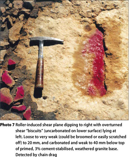
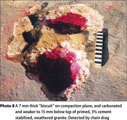
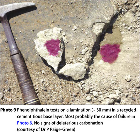
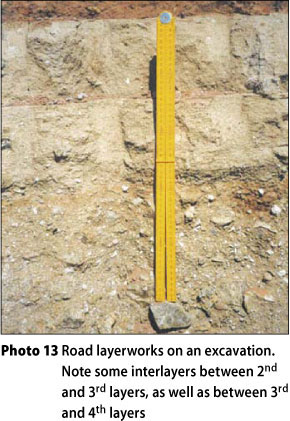
For the purposes of these papers, a weak layer or interlayer is regarded as any layer that is weaker than was assumed in the design and that has a practical measurable thickness, t, of > 1 mm. Such layers are often referred to as "laminations", "biscuits" or, less often, "false layers" (Bergh 1979) or "pie crusts" (Gray 1979) (see Photos 5, 6, 7, 8, 9, 10 and 11).

In addition, a weak interface, on the other hand, is a condition of minimum friction road - possible weak interlayer directly under the surfacing seal (slip) between two layers, or parts of a layer, normally in the upper 75 mm or so in the cemented base, and has no virtual thickness, i.e. t ~ 0 mm. Such weak layers, interlayers, laminations and/or interfaces are illustrated in the afore-mentioned photos.
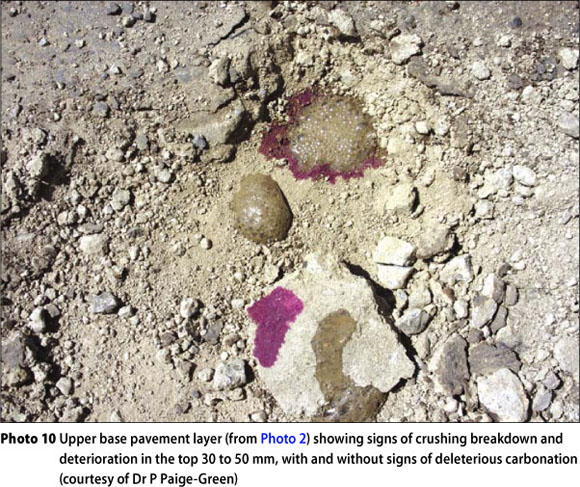
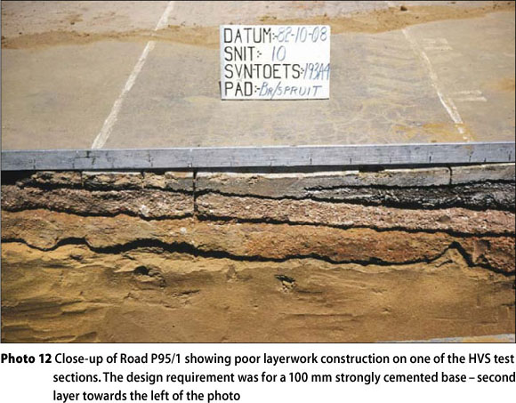
In terms of consistency, such interlayers may be loose, i.e. with no unconfined com-pressive strength (UCS), and at a relatively lower density, be relatively weak, i.e. with a reduced UCS, or relatively soft (moist and/or plastic) (see Photos 10, 11, 12, 13 and 15).
In practical terms of soil structure, they may be intact (structureless), sheared or laminated. The term "laminations" or, colloquially, "biscuits", is often applied to all of these forms, in spite of the former meaning thinly layered (i.e. geologically up to 10 mm) and the latter implying a relatively hard but brittle material. However, a smooth or striated flat surface (i.e. interface as defined above with thickness t < 1 mm) is usually found immediately below most forms of weak interlayers. Therefore, smooth, flat, inclined or curved surfaces representing interfaces between compacted layers or shear planes within layers are also regarded as forms of undesirable weak interlayers. The detection and laboratory/field testing of interlayers and interlayer shear transfer between layers (including asphalt layers) are, among others, discussed by Oba and Partl (2000), Diakhate et al (2006), and Canestrari et al (2005). The term "chemically stabilised" is used here to mean a material modified or cemented with cement or lime as envisaged in Technical Recommendations for Highways (TRH) 13 (NITRR 1986a).
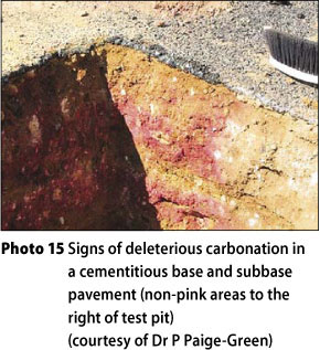
Regarding carbonation in terms of road structure, a weak layer may or may not be directly related to the existence of a lamination or a weak interface, as it could develop during construction or because of physicochemical breakdown (Netterberg 1991, 1994), or it could be due to a traffic-associated crushing failure as discussed above. However, carbonation of road layers (or parts thereof) should be seen in the context of the layer's use within a road pavement. A strongly cemented layer might show signs of carbonation, but the strength of the carbonated material is still adequate for its use and purpose in the pavement. This could be described as "non-deleterious" carbonation (or simply carbonation), whereas when carbonation causes the properties of the material to deteriorate to the extent that the layer cannot fulfil its intended function, this is known as "deleterious" carbonation, in the context of this set of papers.
CRITICAL IMPORTANCE OF A STRONG UPPER BASE
Although it has generally been appreciated for many years (e.g. Bergh 1979) that the upper base must be relatively strong and intact, it is not generally appreciated just how critical this is, especially in the case of a pavement with a cemented base under a surface treatment or thin asphalt surfacing. Experience has shown that such pavements constructed in the last 20 to 30 years do not distress so much by cracking as by rippling and shoving of the thin surfacing associated with a weak interlayer, usually some 3 to 20 mm thick, between the base and the surfacing.
The following section demonstrates the importance of a strong upper base layer, and is based largely on the original work by De Beer (1989a, 1989b, 1990) and De Beer et al (1989).
Heavy Vehicle Simulator (HVS)-DCP correlation
Testing of such pavements under the HVS and correlation of the results with special DCP testing of the same pavements resulted in the prediction model given in Equation 1 (De Beer 1989b, 1990; De Beer et al 1989):
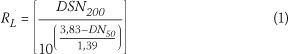
where:
RL = Linear rate of deformation (rutting) in mm/million equivalent standard axles (MESA) (See note on MESA after Equation 2)
DNS0 = Average penetration rate in upper 50 mm of pavement, including surfacing in mm/blow (penetration depth measured after every blow)
DSN200 = Total number of blows in upper 200 mm of pavement, including the surfacing (DCP penetration depth measured after every blow) Probability of regression = 50%, R2 = 76%, n = 29.
As the rate of deformation on lightly cemented pavements appears to be linear (De Beer 1989a, 1990), Equation 1 can be rewritten as:

Where:
CAPt20 = Structural capacity in terms of MESA to an assumed additional rut depth of (20 - R) mm, measured from an existing rut depth (R) in mm.
Note that MESA = Million Equivalent repetitions of a Standard 80 kN (8 200 kg) Axle with four tyres at 520 kPa tyre pressure.
In this paper the research based on the DCP and HVS testing was done in such a way that the relative damage coefficients for permanent deformation (d) could be determined. These values ranged between 1,2 and 1,8 for the pavements investigated in the relatively dry state, and were used to convert actual HVS tyre loading to equivalent loading repetitions on which Equations 1 and 2 are based. The usual value of d ~ 4 was therefore not used in this study. (For the original work see Chapter 4 in De Beer 1990.)
This model is the same as that used in the CSIR computer software (CSIR 2007) for the analysis and classification of DCP survey data on lightly cemented (C3 and C4 materials) pavements as defined in TRH 4 (COLTO 1996). As stated, the above model (Equation 2) was derived using actual HVS loading repetitions of a given wheel load, converted to MESA or Equivalent Standard Axle Load (ESAL) or E80 units. However, a convenient nomogram to an additional rut depth of [20 - R] mm (modified from the original Figure 13 in De Beer et al 1989) is provided in Figure 1. This shows the approximate structural capacity (CAPt20) in MESA for an additional rut depth of 20 mm, hence the term [20 - R] = 20 mm, with R = 0 mm.
The empirical model given in Equation 2 applies strictly to pavements incorporating C3 or C4 cemented bases, i.e. UCS between 0,5 and 3 MPa (NITRR 1986a, 1986b), with the following DCP characteristics: DSN800: 200 to 750 blows, B > 0 and A < 3 000 (see De Beer 1989b, 1990), a 20 mm maximum terminal rut depth, DN50: 0,5 to 4 mm/blow, and an equivalent structural capacity of up to 20 MESA. However, note that relatively higher values of DN50 (up to 9,5 mm/blow) are also shown in Figure 1, illustrating relatively low associated MESAs. Figure 1 also supplies the DSN50 (total number of blows to penetrate upper 50 mm) associated with DN50 on the vertical axis. It is, however, cleai that even under conditions of relatively high DCP penetration rates in the top 50 mm (if the above model is extrapolated beyond DN50 of 4,0 mm/blow), relatively low structural capacities (MESA) are indeed indicated, which carry some engineering value. For this reason Figure 1 is extrapolated beyond DN50 = 4,0 mm/blow.
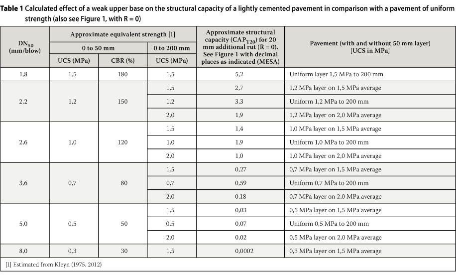
Based on field observations by the authors and applying the methodology given above (HVS and DCP), the effect of a weak upper base layer was investigated. The results of this analysis are summarised in Table 1.
Three important observations are apparent from this analysis (Table 1):
Firstly, for the upper 200 mm of the pavement with an average strength of UCS = 1,5 MPa, a reduction in strength of only 300 kPa in the upper 50 mm to 1,2 MPa will roughly halve the structural capacity from 5,2 to 2,7 MESA. A reduction to 1,0 MPa will reduce the capacity to about 2 MESA, while a strength of 0,7 MPa (~ equivalent to a California Bearing Ratio - CBR - of about 80%) will reduce the capacity to about 0,3 MESA. Reductions of strength of this order are not readily apparent to inexperiencedpersonnel and this pavement would probably be surfaced. Although Figure 1 should be regarded as only approximate, in situ DCP-derived UCS strengths as low as 0,3 to 0,5 MPa have been measured in the upper 50 to 75 mm in un-distressed areas of pavements which suffered premature distress within weeks to months of opening to traffic. These former predictions are, therefore, considered reasonable. Although it is probably true that the DCP disturbs the upper base and that the true strengths are therefore higher, the method was based on DCP penetration rates correlated with actual pavement behaviour under the HVS rather than actual UCS values only. Any disturbance has therefore been taken into account. The extremely deleterious nature of a weak upper pavement is well shown by the sample calculations using Equation 2, presented in Table 1.
The second important observation is that it is better for the cemented layer to be "uniformly weaker" throughout than to have the same degree of weakness only in the upper base (~ top 50 mm). For example, the model in Equation 2 predicts that a pavement with an average strength of 1,5 MPa in the upper 200 mm and weak 1,3 MPa upper base of 50 mm would have a capacity of about 2,7 MESA, whereas a pavement with the same 1,2 MPa strength throughout the upper 200 mm would have a capacity of about 3,3 MESA. Similarly, a 200 mm-thick 0,7 MPa pavement (equivalent to a CBR of about 80%) would have a structural capacity of about 0,5 MESA - a plausible number, i.e. twice that of a 1,5 MPa pavement with a 50 mm weak upper layer of 0,7 MPa (Table 1).
A third important observation is that if the strength of the weak upper layer is kept constant, increasing the average strength of the cemented layer decreases rather than increases the capacity. For example, for a 1,2 MPa weak layer, increasing the average strength of the upper 200 mm from 1,5 to 2,0 MPa decreases the structural capacity from 2,7 to 1,9 MESA. This is most probably due to some "strength balancing" in the top 200 mm of the pavement.
Although any limitations of the model have been ignored in the simplistic analysis presented in Table 1, the results should be at least semi-quantitatively valid and serve to illustrate the critical importance of avoiding a weak interlayer between the base and surfacing layers.
Relatively weak layer on strong sublayer
The failure mode assumed in this analysis is that of weakening and/or crushing of the weak layer on a relatively stronger sublayer (see Photos 5, 6, 10 and 11). The apparent anomaly in Figure 1, whereby increasing the strength of the under (sub) layer decreases the structural capacity, can be explained in terms of the structural pavement strength balance. In other words, it is easier to crack a nut by placing it on a harder surface.
CAUSES OF SURFACE WEAKENING
Surface weakening and even surface disintegration of compacted pavement layers - especially those chemically stabilised - during construction is not new and has been recorded from a number of countries in southern Africa and elsewhere. (e.g. Netterberg et al 1987, 1989; Netterberg 1991, 1994). However, it is not widely known and is poorly understood. Known or suspected causes of, contributory factors towards or mechanisms causing a loose or weak layer at the top of a completed pavement layer include the following (mostly after Netterberg 1991, 1994):
■ Very poor-quality gravel or soil: may shear during compaction
■ Organic matter, including penetrating primer, weed killer, sugars: may retard set and/or prevent hardening
■ Aggregate strength: may break down during compaction, especially near the top of a layer
■ Aggregate durability: some aggregates disintegrate spontaneously
■ Stabiliser type and quality ("fit for pur-pose"): suitability for the soil, soundness, age, rate of setting and hardening, slow slaking of quicklime, generation of gas by carbide lime (SANS 824-2006)
■ Conversion of metastable calcium alu-minate hydrates formed during chemical stabilisation of materials containing free or exchangeable aluminium (some laterites and tropical soils) (Sherwood 1993)
■ Excessive or delayed mixing of chemically stabilised material
■ Insufficient mixing ("brief-mix set"): a type of false set (Netterberg, in preparation)
■ Aeration during mixing: another type of false set (Netterberg, in preparation)
■ Poor vertical mixing through layer thickness
■ Vibrating roller set at too high an amplitude
■ Reversing or stopping vibrating roller while it is vibrating
■ Delayed compaction: breaking down of upper part of layer due to compacting partially set, chemically stabilised or partially dried material
■ Inadequate compaction
■ Overcompaction: breaking up of already compacted, semi-hardened material, and production of new faces uncoated by cement or bitumen
■ Grading across to fill slacks instead of cutting to level (see Photos 5 and 12)
■ Incomplete removal of fines to expose good mosaic after slushing and before sealing
■ Spreading of fines on the base to improve the surface finish
■ Slushing or washing out of stabiliser: prohibited on a chemically stabilised layer, but might occur if emulsion-treated finishing methods (light slush, surface enrichment) or over-watering during finishing or curing are used
■ Primer type and quality: penetrating primers applied too soon, hindering cementation (NITRR 1986a, 1986c)
■ Frost damage (has occurred in the eastern Free State and in Lesotho)
■ Bacterial attack: deterioration of bitumen, generation of gas
■ Soluble salt crystallisation and/or hydra-tion (previously common in southern Africa)
■ Acid attack on chemically stabilised material: acidic material, acid rain (personal communication with Johnson (1989) by main author)
■ Sulphate attack on chemically stabilised material
■ Detrimental carbonation of chemically stabilised material (common in southern Africa) from top and bottom of cemented layer (Sampson et al 1987; Netterberg 1991) (see e.g. Photos 7, 8, 10 and 15 with associated failures
■ Drying out of chemically stabilised material (incomplete hydration of cement): even one drying cycle can halve the UCS - probably a common cause (De Wet & Taute 1985)
■ Wetting and drying cycles during curing of a chemically stabilised layer or due to rain: probably a common cause
■ Positive pore water or pore gas (usually water vapour) pressure developed in very hot weather
■ Positive air pressure developed due to a sudden drop in barometric pressure
■ Positive air pressure developed due to capillarity (air breakage, slaking)
■ Thermal buckling
■ Roots
■ Material variability (variable optimum moisture content (OMC), variable UCSs)
■ Emulsion quality and variability ("fit for purpose"): breaking too soon in plant or road, possibly even when within the specification
■ Variability in cement content (even within the specification)
■ Shearing by recycler and vibrator tyres, tamping roller and vibrator drum
■ Faster setting and/or hardening of the cement used than that calculated in the design
■ False setting of cement induced by high temperature
■ Reluctance of water to mix with the material: (hydrophobic material)
■ Difficulty in compacting 300 mm in a single lift while recycling (Netterberg, in preparation)
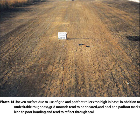
■ Use of a tamping or grid roller too high up in the base layer: disturbance and footprint compaction planes too deep to skim off - see Photo 14 (Netterberg, in preparation)
■ Very high ambient temperatures: water vapour or cutter blistering (entrapment of volatiles), accelerated carbonation, flash setting of cement (possibly aggravated by hot undiluted emulsion), accelerated setting and hardening causing compaction problems and poorer ultimate strength, lower pH of cement, accelerated breaking of emulsion, drying out during compac-tion, softening of emulsion "primer", increased pore sizes due to expansion, conversion of reaction products (Netterberg, in preparation)
■ Almost sole reliance on a recycler for mixing of the materials, water, cement and emulsion in one pass only
■ Absorption of water and bitumen by the aggregate: premature breaking of an emulsion and incorrect OMCs
■ Smectite in the gravel: premature coagulation or retardation of an emulsion
■ Amorphous silica in the gravel: delayed expansion and weakening or decomposition of the cement (Botha et al 2005), later considered by Paige-Green (2009) to be extremely unlikely
■ Initial consumption of lime (ICL) or initial consumption of cement (ICC) of material not satisfied
■ Sodium carbonate in the gravel acting as an accelerator to a cement and/or as a retarder to an emulsion
■ Variation in proportions of old road, borrow material and sand during recycling
■ Problem of laboratory acceptance control by UCS testing of a material stabilised with a mixture of both cement and emul-sion: uncertainty of best curing method
■ Use of laboratory mixes for UCS testing instead of road samples
■ Necessity to consider the optimum total fluid content (OTFC), not just the OMC, for compaction of bitumen-stabilised materials
■ Possible interaction between stabilisers: higher cement contents might accelerate the breaking of an emulsion, while higher emulsion contents might hinder hardening of the cement
■ Incompatibly charged dust particles along the base course-seal interface (McNally 1998) - hypothesis now apparently withdrawn (personal communication with McNally 1999 by main author)
■ Detrimental carbonation of chemically stabilised layer from below or from sides after construction
■ Punching (embedment) of chippings during surfacing or by traffic into a cemented base
■ Traffic (crushing of an already weak layer and/or sliding on smooth compaction planes): the actual cause of the failures, aggravated by overloading and especially high actual tyre-road contact stresses
■ Pick-ups of the seal by tyres
DISCUSSION ON POSSIBLE CAUSES OF SURFACE WEAKENING
The causes, prevention of and remedial measures for all such weakening cannot be discussed in detail here - for some of them see Grant & Netterberg (1984), Kleyn & Buckle (1989) and Netterberg (1991, 1994). However, many are obvious and covered by the standard precautions and specifications (COLTO 1998 Section 8). Some have not been previously identified and will be discussed elsewhere (Netterberg, in preparation) and some are speculative and unproven. The most common causes are believed to be the filling of slacks during the cutting of final levels, overcompaction of a weak aggregate or partially hardened cemented material, salt crystallisation, surface carbonation of a chemically stabilised layer, surface drying out and/or cycles of wetting and drying of a chemically stabilised layer, water vapour pres-sures, the former use of a tar primer on an unhardened chemically stabilised material, and construction during very hot weather, especially with cementitious stabilisers. Some materials perform well in laboratory tests, but have a tendency to form a soft surface or soft base in the field (Bergh 1979).
The use of single-pass mixing is no longer recommended in Australia. At least two passes are recommended, especially for depths exceeding 250 mm (Aust Stab 2000). Weak interlayers probably cause the most problems with chemically stabilised bases, although unstabilised and even G1 crushed stone bases (G1 material as defined in COLTO 1998) are not immune (e.g. Netterberg et al 1989, Wyatt & Thomson 1994). From published (e.g. Paige-Green 1984, 1991, 2009; De Wet & Taute 1985; Bagonza et al 1987) and unpublished results, cement and lime-stabilised materials lose, on average, about half their strength either on carbonation - even after seven years of ideal laboratory curing (Paige-Green 1991) or even after one drying cycle (which may also induce partial carbonation). Some materials may even disintegrate. Weakening due to detrimental carbonation, drying out and/or wet-dry cycles is probably the most common cause of surface weakening of chemically stabilised layers.
DETECTION OF WEAK LAYERS
The current general use of nuclear methods for compaction control and the practice of sampling only before compaction mean that holes are dug in most modern pavements only when failures are investigated or when the pavements are patched. These modern methods have deprived the engineer of an invaluable method of quality control for the detection of a variety of defects, as well as for the best measurement of layer thickness.
It is also clear that specifications and engineering judgement have failed to prevent the large number of cases of premature distress known. It is therefore considered that additional means are required. These could include:
■ Visual inspection of trial holes for lami-nations, compaction planes and, after spraying with phenolphthalein solution (Netterberg 1984), for adequacy of mixing and depth of stabilisation, including filling of slacks with untreated material or deteriorated windrow material.
■ Testing for carbonation by spraying of phenolphthalein solution and diluted hydrochloric acid (Netterberg 1984; Paige-Green et al 1990) on the surface of completed chemically stabilised layers. (Note that in chemical soil stabilisation, carbonation almost invariably weakens the stabilised material.)
■ Visual inspection of the surface of completed layers aided by simple test methods, such as:
■ Tapping or dragging a hammer or pick handle across the layer and listening to the tone of the sound produced.
■ Dragging a simple 2 m length of chain across the layer (see Photo 4).
■ An electromechanical sounding device or, even better, a simple chain drag as specified in ASTM D 4580-03 (2009b).
■ Possibly a rapid vehicle-mounted infrared method as used on bridge decks (ASTM D 4788-03 2009a) for longer lengths of road.
■ More frequent measurement of the density at various depths, such as from 0 to 50 mm, 50 to 100 mm and 100 to 150 mm, instead of just the usual 150 mm. In this connection it is important to note that sand has to be calibrated for a particular depth of the hole (NITRR 1986b). A nuclear gauge does not determine moisture content to the depth of the density probe when the direct transmission method is used, but only to a single depth which may be as much as 200 mm (or more) by the flush backscatter method (NITRR 1986a). Gravimetric moisture content measurements may therefore be necessary for each depth. The calculation method for measuring the density of different layers by taking depth probe readings at different depths is only approximate.
■ If a chemically stabilised layer has been badly cured - even allowed to dry partially only once - the upper layer has probably been weakened.
DISCUSSION ON DETECTION METHODS
Because the standard tests for grading, plasticity and strength are all carried out in the laboratory on a sample from the full thickness of the layer, they are insensitive to the presence of a thin layer of deleterious material even when taken after compaction. Even gradings carried out on samples taken from the full thickness of distressed areas do not necessarily indicate the presence of an interlayer of fines between the base and surfacing (Sampson et al 1985).
Standard deflection surveys are not appropriate for the detection of a weak base (Grant & Netterberg 1984) or a weak upper layer of a cemented base, as a low (maximum surface) deflection may be maintained by the rest of the layer (Kennedy & Lister 1978). However, the radius of curvature, which is largely affected only by the upper 0,4 m of the pavement (Grant & Walker 1972), will generally be lower (Grant & Netterberg 1984) and has been used by the main author with more success. In the case of falling weight deflectometer (FWD) surveys, the use of the base layer index (BLI) (Horak 2008) might also prove successful.
Such techniques have, of course, been used for many years, but should probably be a requirement, not an option. Once a weak layer at any depth has been detected, its strength can be measured by means of the DCP if it is not too thin (say t > 10 mm) and its effect on structural capacity then assessed mechanistically or, if in the upper cemented base, by means of the CSIR WinDCP computer program (CSIR 2007), or manually by means of Figure 1 or Equation 1. When dealing with thin layers it is advisable to take DCP measurements after every blow close to such layers rather than after the usual five blows. How well the DCP evaluates hard biscuits separated by smooth planes is not known.
Other possible methods for the determination of the strength of thin layers include the rapid compaction control device (RCCD) (De Beer et al 1993), a Clegg hammer (Clegg 1983; ASTM D 5874-02 2008) and other types of portable falling weight testers (Hildebrand 2003). In the case of the Clegg hammer, it may be necessary to consider also readings after one or two blows in preference to just the standard four blows. The bond strength between cemented layers can probably be measured on cores by using ASTM C 1245-06 (2007), or as was reported by Canestrari et al (2005).
Importance of correct zero point measuring with the DCP
The importance of taking the correct zero point (the top of the vertical shoulder of the DCP level with the top of the surfacing, which is not removed, as in TMH 6 (NITRR 1984)) and also the "softness" of the surfacing into account can be illustrated by means of a sensitivity analysis. An investigation of a new road with a rich seal on a C3 base, which had suffered premature distress due to a weak upper base, is presented in Table 2. This table shows that, in the redefined case, taking the zero at the point of inflection, i.e. effectively removing the generally new, hot, soft surfacing from the DCP analysis, resulted in an overall increase in the apparent structural capacity, in many cases a substantial increase. This was originally shown by Netterberg (in preparation).

In Part 2 of this set of papers (De Beer et al 2012 - see page 43 of this edition), the so-called traffic-associated "crushing failure" of lightly cemented layers is also discussed, which demonstrates the effect of tyre contact stresses on these pavement layers.
PREVENTION OF WEAK INTERLAYERS
Most weak layers, interlayers, laminations and/or interfaces can be prevented by good construction practices. For example, the South African standard specifications for road and bridge works (COLTO 1998) include a number of specific precautions clearly designed to prevent such interlayers:
■ The minimum thickness of compacted pavement layers shall be 100 mm (para 3207 (b) (iii)) except in restricted areas where it may be as thin as 75 mm (para 32707 (b)(ii)).
■ The underlying layer shall be free of loose material before a layer of plant-mixed, paver-laid material is placed upon it (para 3703).
■ Mixing in of a chemical (para 3503 (d)) and, presumably also intended, a bituminous (para 3505 (b)) stabiliser shall be carried out over the full depth to be stabilised.
■ Compaction of pavement layers shall be carried out so as to ensure that specified densities are obtained without damaging the lower layers (para 3207 (b)(i)).
■ During compaction, the crust of a chemically stabilised layer shall be lightly harrowed or scarified before final rolling, if required by the engineer, in order to prevent the formation of laminations near the surface of the layer (para 3503(f)).
■ The specified density of a crushed stone base shall be obtained throughout the entire layer, except when only water-rolled and, when so required by the engi-neer, shall be tested at various prescribed depths (para 3604(b)).
■ In restricted areas the required densities of pavement layers shall be obtained throughout the thickness of the layer (para 3208 (b)(ii)).
■ A completed crushed stone base layer shall be free from surface laminations after compaction (para 3604 (b)) and after slushing (para 3604(c)(i)).
■ All excess fines shall be removed from the surface of a gravel (para 3403 (b)(i)) or crushed stone (para 3604 (c)(i)(ii)) base.
■ Curing of a chemically stabilised layer for at least seven days is carefully specified and it is stated that drying out or wet-dry cycles may be cause for rejection if the layer is damaged thereby (para 3503(h)).
■ No priming shall be carried out on a base which is visibly wet or which is at a moisture content in excess of 50% of the OMC (para 4104).
■ Before priming, the base shall be broomed and cleaned of all loose material (para 4105).
■ Asphalt shall not be placed if free water is present on the working surface or if the moisture content of the underlying layer, in the opinion of the engineer, is too high, or if the moisture content of the upper 50 mm of the base exceeds 50% of the OMC (para 4205(b)).
■ Before applying a tack coat or asphalt, the surface shall be broomed and cleaned of all loose or deleterious material (para 4205(c)(ii)).
■ Before applying a seal, the moisture content of the upper 50 mm of base shall be less than 50% of the OMC (para 4304(b)) and shall be cleaned of all dust, dirt, dung, oil, etc (para 4304 (d)(i)).
■ No asphalt overlay (para 4205 (b)) or reseal (para 4304(b)) shall be placed immediately after a rainy spell on an existing cracked or highly permeable surfacing resulting in the trapping of moisture.
In addition to the specific precautions listed above, the aggregate strength and durability requirements for G1 - G3 crushed stone (para 3602(a)) and G4 - G6 gravel materials (para 3402(a)), and also the soluble salt requirement for both crushed stone (para 3601(b)) and gravel (para 3402(c)) are also intended in part to prevent the formation of weak interlayers due to aggregate degradation and salt damage respectively.
However, in spite of all these precautions and earlier versions of many of them dating back many years, cases of premature distress due to weak interlayers continue to occur. This may be due to insufficient appreciation of just how deleterious such interlayers really are, difficulty in complying with some of the precautions and requirements, and/or inadequate supervision. In addition, so many cases are known where the interlayers must have been built-in as such that it must be concluded that they were simply not noticed. Currently, reliance is placed solely on the supervisory staff to detect such layers by whatever means are at their disposal, and no specific tests are specified or in general use. It is clear that reliance solely on visual inspection has proved inadequate in many cases.
Suggested improvements to the above specifications include the following:
■ Underlying layers should always be free of loose material.
■ Holes should be dug in compacted layers to check for laminations, and/or weak interlayers, adequacy of mixing and, by spraying with phenolphthalein solution (Netterberg 1984), for an even distribution of stabiliser throughout the layer, from top to bottom (i.e. ~ ph > 10).
■ The engineer should have the power to test the density, grading and plasticity at any depth in all pavement layers.
■ A tar primer should not be applied to a chemically stabilised layer sooner than about seven days after compaction, nor, indeed, any highly penetrating primer until the layer has been cured by other means (NITRR 1986b: 50).
■ A fluid cutback primer such as MC-30 should not be permitted as a curing membrane as it is ineffective at preventing both moisture loss (Bofinger et al 1978 in TRL & ODA 1993) and carbona-tion (Netterberg et al 1987) for more than a few days. Even a prime such as MC-30 can weaken a cemented material (HRB 1949; Netterberg 1994) possibly due to hindrance of the cement hydration over the depth of penetration (RRL 1952). The surface moisture content should be such as to prevent penetration (HRB 1949). However, this may cause water vapour blistering in hot weather (Netterberg 1994).
■ Additional precautions may be required when utilising marginal or substandard materials (Netterberg et al 1989).
■ Embedment seldom occurs on a crushed stone base. Embedment due to a false layer on a base can be prevented by either carrying out the final compaction with a diluted emulsion or ripping up the top 20 mm after compaction and treating it with diluted emulsion (Bergh 1979). In both cases the prime is omitted.
CONCLUSIONS
The experience of the authors, HVS testing and careful DCP testing have shown that the presence of weak layers, interlayers, laminations and/or interfaces is far more deleterious to structural road pavement performance than is commonly assumed. In particular, a thin interlayer of weaker material between a cemented base course and a thin surfacing can lead to extensive distress within weeks or months of opening to traffic. Such distress can usually be predicted by means of careful inspection, as well as by careful DCP testing. The creation of such weak layers, interlayers and/or laminations must therefore be prevented at all costs, even at the expense of other aspects such as surface finish. The causes of weak layers, interlayers, laminations and/or interfaces are many and some may have more than one cause, but most can be prevented simply by application of known good construction practices. However, such conditions are not always prevented by the application of the standard precautions. Engineering judgement and stricter application of visual inspection, supplemented by simple field tests, are therefore required.
ACKNOWLEDGEMENT
This paper is published with the approval of the Executive Director of the CSIR Built Environment Unit.
REFERENCES
ASTM International 2007. ASTM C 1245-06: Standard test method for determining bond strength between hardened roller compacted concrete and other hardened cementitious mixtures (point load test). Annual Book of ASTM Standards, Vol 4, 04.02, pp 668-672. [ Links ]
ASTM International 2008. ASTM D 5874-02: Standard test method for determination of the impact value (IV) of a soil. Annual Book of ASTM Standards, Vol 4, 04.08, pp 1706-1714. [ Links ]
ASTM International 2009a. ASTM D 4788-03:Standard test method for detecting delaminations in bridge decks using infrared thermography. Annual Book of ASTM Standards, Vol 4, 04.03, pp 490-492. [ Links ]
ASTM International 2009b. ASTM D 4580-03: Standard practice for measuring delaminations in concrete bridge decks by sounding. Annual Book of ASTM Standards, Vol 4, 04.03, pp 464-467. [ Links ]
Aust Stab (Australian Stabilization Industry Association) 2000. Aust Stab News, 6.1: 4. [ Links ]
Bagonza, S, Peete, J M, Newill, D & Freer-Newish, R 1987. Carbonation of stabilized soil cement and soil-lime mixtures. Proceedings, Seminar H, PTRC Transport and Planning Summer Annual Meeting, Bath, UK, pp 29-48. [ Links ]
Bergh, A O 1979. Discussion. Proceedings, 3rd Conference on Asphalt Pavements for Southern Africa, Durban, Vol 2, Paper 40, pp 155-157. [ Links ]
Botha, P, Semmelink, C J & Raubenheimer, J 2005. The real cause of detrimental carbonation in stabilized layers and possible solutions. Proceedings, Conference on the Treatment and Recycling of Materials for Transport Infrastructure (TREMTI), Paris, October, Communication C012. [ Links ]
Canestrari, F, Ferrotti, G, Partl, M N & Santagata, E 2005. Advanced testing and characterization of interlayer shear resistance. Transportation Research Record, 1929: 68-78. [ Links ]
Clegg, B 1983. Design-compatible control of basecourse construction. Australian Road Research, 13(2): 112-122. [ Links ]
COLTO (Committee of Land Transport Officials) 1996. Structural design of flexiblepavements for interurban and rural roads. Draft TRH 4: 1996, Pretoria: Department of Transport. [ Links ]
COLTO (Committee of Land Transport Officials) 1998. South African standard specifications for road and bridge works, 1998, Midrand: SAICE. [ Links ]
CSIR 2007. WinDCP Software, Version 5.1.10002. Available at: http://asphalt.csir.co.za/DCP/index.htm (last accessed on 11 April 2012). [ Links ]
De Beer M, Maina J W & Netterberg, F 2012. Mechanistic modelling of weak interlayers in flexible and semi-flexible road pavements - Part 2. Journal of the South African Institution of Civil Engineering, 54(1) (this issue). [ Links ]
De Beer, M 1985. Behaviour of cementitious subbase layers in bitumen base road structures. MEng thesis, University of Pretoria, Pretoria. [ Links ]
De Beer, M 1989a. Compression failure of lightly cementitious materials. Research Report DPVT 36, Pretoria: CSIR Division of Roads and Transport Technology. [ Links ]
De Beer, M 1989b. Dynamic Cone Penetrometer (DCP)-aided evaluation of the behaviour of pavements with lightly cementitious layers. Research Report DPVT 37, Pretoria: CSIR Division of Roads and Transport Technology. [ Links ]
De Beer, M 1990. Aspects of the design and behaviour of road structures incorporating lightly cementitious layers. PhD thesis, University of Pretoria, Pretoria. [ Links ]
De Beer, M, Kalombo, D K & Horak, E 1993. Rapid compaction control for trench reinstatements and pavement layers. Proceedings, 13th Annual Transportation Convention (ATC '93), Pretoria, 28 June - 1 July. [ Links ]
De Beer, M, Kleyn, E G & Savage, P F 1989. Advances in pavement evaluation and overlay design with the aid of the Dynamic Cone Penetrometer (DCP). Proceedings, 2nd International Symposium on Pavement Evaluation Overlay Design, Rio de Janeiro, 44 pp. [ Links ]
De Wet, L F & Taute, A 1985. Durability of stabilized materials. Proceedings, Annual Transportation Convention (ATC), Paper FB, Pretoria, pp 1-15. [ Links ]
Diakhate, M, Phelipot, A, Millien, A & Petit, C 2006. Shear fatigue behaviour of tack coats in pavements. Road Materials and Pavement Design, an International Journal, 7(2): 201-222. [ Links ]
Grant, M C & Netterberg, F 1984. Determining the cause of distress in pavements with thin bituminous surfacings. Proceedings, 4th Conference on Asphalt Pavements for Southern Africa, Cape Town, pp 655-665. [ Links ]
Grant, M C & Walker, R N 1972. The development of overlay design procedures based on the application of elastic theory. Proceedings, 3rd International Conference on Structural Design of Asphalt Pavements, London, Session V11, pp 1155-1165. [ Links ]
Gray, J W 1979. Discussion. Proceedings, 3rd Conference on Asphalt Pavements for Southern Africa, Durban, Vol 2, p 155. [ Links ]
Hildebrand, G 2003. Comparison of various types of bearing capacity equipment. Nordic Road and Transport, 3: 12-14. [ Links ]
Horak, E 2008. Benchmarking the structural condition of flexible pavements with deflection bowl parameters. Journal of the South African Institution of Civil Engineering, 50(2): 2-9. [ Links ]
HRB (Highway Research Board) 1949. Prevention of moisture loss from bituminous materials. HRB Research Report No 8 - P, Washington, DC: Highway Research Board. [ Links ]
Johnson, D 1989. Jeffares & Green, Consulting Engineers, South Africa, Personal Communication to F Netterberg. [ Links ]
Kennedy, C K & Lister, N W 1978. Prediction of pavementperformance and the design of overlays. Report 833, Transport and Road Research Laboratory (TRRL), Crowthorne, UK. [ Links ]
Kleyn, E G & Buckle, L J 1989. Why prime? Proceedings, 5th Conference on Asphalt Pavements for Southern Africa, Mbabane, Session IX, pp 11-13. [ Links ]
Kleyn, E G 1975. Die gebruik van die dinamiese kegel-peilstaaf (DKP). Report 2/74, Transvaal Roads Department (TRD), Pretoria: TRD (in Afrikaans). [ Links ]
Kleyn, E G 2012. TPA Graph 82.03. Personal communication. [ Links ]
McNally, G H 1998. Soil and Rock Construction Materials. London: Spon. [ Links ]
McNally, G H 1999. Douglas Partners, Consulting Engineers, Australia, Personal Communication to F Netterberg. [ Links ]
Netterberg, F (in preparation). The Trans-Caprivi Highway: A lesson in hot weather stabilisation. [ Links ]
Netterberg, F 1984. Rapid field test for carbonation of lime or cement treated materials. NITRR Research Report RS/2/84, Pretoria: CSIR, National Institute for Transport and Road Research. [ Links ]
Netterberg, F 1991. Durability of lime and cement stabilization. In: Concrete in Pavement Engineering. Halfway House, South Africa: Portland Cement Institute. [ Links ]
Netterberg, F 1994. Surface disintegration of primed pavement layers and blistering of bituminous surfac-ings. Research Report RR 90/275, Pretoria: South African Department of Transport (DoT). [ Links ]
Netterberg, F, Paige-Green, P, Mehring K & Von Solms, C L 1987. Prevention of surface carbonation of lime and cement stabilized pavement layers by more appropriate curing techniques. Proceedings, Annual Transportation Convention (ATC), Pretoria, Paper 4A/X. [ Links ]
Netterberg, F, Van der Vyver, I C & Marais, C P 1989. Some problems experienced during the construction of a substandard base course for a very low volume surfaced road. Proceedings, 5th Conference on Asphalt Pavements for South Africa, Mbabane, Session 1X, pp 28-31. [ Links ]
NITRR (National Institute for Transport and Road Research) 1984. Special methods for testing roads. Draft TMH 6, Pretoria: CSIR, NITRR. [ Links ]
NITRR (National Institute for Transport and Road Research) 1986a. Cementitious stabilizers in road construction. Draft TRH 13, Pretoria: CSIR, NITRR. [ Links ]
NITRR (National Institute for Transport and Road Research) 1986b. Standard methods of testing road construction materials. TMH 1, 2nd ed., Pretoria: CSIR, NITRR. [ Links ]
NITRR (National Institute for Transport and Road Research) 1986c. Prime coats and bituminous curing membranes. TRH 1, Pretoria: CSIR, NITRR. [ Links ]
Oba, K & Partl, M N 2000. Non-destructive IR-thermography for distress detection in asphalt pavements and bridge deck surfacings. Road Materials and Pavement Design, an International Journal, 1(4): 407-418. [ Links ]
Paige-Green, P 1984. A laboratory investigation into the influence of carbonation on the strength of lime-stabilized materials. Proceedings, 8th Regional Conference for Africa on Soil Mechanics and Foundation Engineering, Harare, Vol 1, pp 403-406. [ Links ]
Paige-Green, P 1991. The long-term durability of lime-treated soils. Proceedings, 10th Regional Conference for Africa on Soil Mechanics and Foundation Engineering, Maseru, Vol 1, pp 193-196. [ Links ]
Paige-Green, P 2009. A reassessment of problems affecting stabilized layers in roads in South Africa. Proceedings, 3rd International Symposium on the Treatment and Recycling of Materials for Transport Infrastructure (TREMTI), Antigua, Guatemala, 18-20 November. [ Links ]
Paige-Green, P, Netterberg, F & Sampson, L R 1990. The carbonation of chemically stabilised road construction materials: guide to its identification and treatment. Research Report DPVT 123, Pretoria: CSIR Division of Roads and Transport Technology. [ Links ]
RRL (Road Research Laboratory) 1952. Soil mechanics for road engineers. London: HMSO. [ Links ]
Sampson, L R, Emery, S J & Rose, D 1985. Investigation into premature pavement distress at four sites in the Cape Province. Proceedings, Annual Transportation Convention (ATC), Pretoria, Paper FB. [ Links ]
Sampson, L R, Netterberg, F & Poolman, S F 1987. A full-scale road experiment to evaluate the efficacy of bituminous membranes for the prevention of in-service carbonation of lime and cement stabilized pavement layers. Proceedings, Annual Transportation Convention (ATC), Paper 4A/IX. [ Links ]
SANS 824-2006. South African National Standard: Lime for soil stabilization, ed. 2.1. Pretoria: South African Bureau of Standards. [ Links ]
Sherwood P T 1993. Soil stabilization with cement and lime. State of the Art Review, Transport Research Laboratory (TRL), London: HMSO, 153 p. [ Links ]
TRL & ODA (Transport Research Laboratory and Overseas Development Administration) 1993. A guide to the structural design of bitumen-surfaced roads in tropical and sub-tropical countries, 4th ed. Overseas Road Note 31, Overseas Centre, TRL, Crowthorne, UK. [ Links ]
Wyatt, P J & Thomson, A 1994. Premature failures of thin asphalt wearing courses constructed on highly compacted crushed stone bases. Proceedings, 6th Conference on Asphalt Pavements for Southern Africa, Cape Town, Vol 2, Session VI, pp 156-167. [ Links ]
 Contact details:
79 Charles Jackson Street
Weavind Park
Pretoria 0184 South Africa
T +27 12 846 7051
F: +27 86 270 8137/8
E: fnetterberg@absamail.co.za
Contact details:
POBox395
CSIR Built Environment
Pretoria 0001 South Africa
T +27 12 841 2953
F: +27 12 842 7114
E: mbeer@csir.co.za

DR FRANK NETTERBERG is an independent researcher and specialist consultant on pavement materials and geotechnics. He graduated from the University of Cape fi)wn with a BSc in geology in 1960 and a BSc Hons in 1963 and a PhD in 1970 in Engineering geology from the University of the Witwatersrand, and is a Chartered Engineer and Geologist, a registered Professional Scientist, a Fellow of ICE and SAIEG, and a Member of SAICE and AEG. He has been employed by mining companies, consulting engineers, the CSIR and the University of the Witwatersrand. His research and consulting interests include marginal and unusual materials, pedocretes, soluble salt damage, stabilisation, and active clay roadbeds on which he has published many papers and for which he has received a number of awards.

DR MORRIS DE BEER is a principal researcher at the CSIR (Council for Scientific and Industrial Research) Built Environment Unit, and associate editor of the International Journal for Road Materials and Pavement Design (RMPD). He obtained his BSc (Hons), Masters and PhD degrees in Civil Engineering from the University of Pretoria, where he also acts as guest lecturer. He is registered with the Engineering Council of South Africa as a professional engineer, and is a member of SAICE. He also served on various international technical committees, such as the International Society of Weigh in Motion (ISWIM) and Rilem. His research focus is on structural road pavement behaviour, road design, road materials, and vehicle-tyre-road interaction. He is a member of the Tansport Infrastructure Engineering group at the CSIR Built Environment Unit.
Note
The 27 photos and 12 figures are numbered continuously throughout Part 1 and Part 2 of this two-part set of papers. However, the references and equation numbers are specific to each part.

