


Serviços Personalizados
Artigo
 Inglês (pdf)
 Artigo em XML
 Referências do artigo
Indicadores

Links relacionados
-
 Citado por Google
 -
 Similares em Google
Compartilhar

 Permalink
Journal of the South African Institution of Civil Engineering
versão On-line ISSN 2309-8775
versão impressa ISSN 1021-2019
J. S. Afr. Inst. Civ. Eng. vol.51 no.2 Midrand Out. 2009
TECHNICAL PAPER
Optimising structures using the principle of virtual work
A Elvin; R Walls; D Cromberge
ABSTRACT
This paper presents a method for optimising structures with a given geometry and loading based on the principle of virtual work. The Virtual Work Optimisation Method, or VWOM, that was developed minimises the mass of the structure while meeting building code strength requirements, and flexibility (or deflection) criteria. The optimisation can be readily constrained by grouping together members with the same sectional properties. The VWOM automates most of the design process, obviating the requirement of experience and expertise in stiffening a structure.
Three case studies were conducted using the VWOM: (i) the benchmark optimisation ten-member truss; (ii) a truss frame designed by professional engineers; and (iii) a 24-storey frame. The results of the VWOM were compared with published or available solutions. The VWOM produced structures that were 0,9 to 15,1% lighter than those produced by the methods used in the comparisons. If every member was allowed to have its own sectional properties, the VWOM found even lighter structures (by as much as 19,5%). The VWOM is less computationally expensive than the comparison methods, requiring two or three orders of magnitude fewer iterations to converge to the solution.
Keywords: automated member selection, discrete sections
INTRODUCTION
In general, the design of structures requires that each member and the structure as a whole meet two sets of requirements, namely strength and flexibility (or deflection) criteria. If the structure is designed to building codes, then the strength requirement should be met automatically. On the other hand, it is not always clear how and where the structure should be stiffened to meet the deflection criterion. In most cases, the engineer uses his or her intuition and experience to reduce deflection. Often manual iterative approaches of the trial-and-error type are used to reach the target deflection specified by the code.
This paper presents a method for determining the stiffness of the identified member(s) within a structure in order to meet the target deflection in an optimal way. The problem addressed can be stated as follows: to minimise the total mass of the structure while meeting both strength and deflection requirements. The geometry of the structure, i.e. the position of the nodes and how they are connected, and the loading are given and it is required to find each member's section in an overall optimal way. In this paper an "optimal structure" is defined as the lightest possible structure that satisfies all load resistance and deflection criteria. Since a minimum is sought, the method will generally require iteration and, to be tractable, it will have to be automated (with no human expertise required).
The optimisation of a structure with a given geometry has been extensively researched. A few examples of optimisation methods are: the genetic algorithm (Erbatur et al 2009), tabu search (Kargahi et al 2006), discrete effective optimisation (Gutkowski et al 2006) and ant colony optimisation (Camp et al 2005). None of these methods selects the structural member's sections based on structural mechanics; rather, a search procedure is used. They require many (hundreds, thousands and in some cases tens of thousands) iterations to produce a solution. There is no guarantee that the solution is a local or a global minimum. On the other hand, performing a straightforward exhaustive search of all possible combinations of member sections, to obtain the minimum mass, even of a simple structure, would take too much time (measured in centuries), even with current modern computers. Thus it is well recognised that structural optimisation is a difficult problem.
To complicate matters, if the structure to be optimised has too many sections, it becomes difficult to construct and prone to errors. For this reason and to simplify the design process, in engineering practice members are grouped together and assigned to the same section. As the number of member groups decreases, so the mass of the overall structure increases. There should be a balance between the complexity of the design and the economy due to mass savings. Grouping members imposes constraints on the optimisation problem.
In this paper the principle of virtual work forms the basis of the optimisation algorithm. The method developed is called the Virtual Work Optimisation Method, or VWOM. The paper is organised as follows: first, the principle of virtual work is presented together with the assumptions made. The VWOM, in particular, and how the strength requirements and deflection criteria are met, are described. The optimisation curve produced by the iterations of the VWOM, together with notes on increment size and member grouping constraints, are discussed. Next, three case studies are considered: (i) the standard ten-member benchmark truss; (ii) a truss frame; and (iii) a 24-storey frame. In all cases the results from the VWOM are compared with published optimisation solutions. Finally, future research areas are identified and we consider how the VWOM can be extended.
THE PRINCIPLE OF VIRTUAL WORK
For any solid, the well-known principle of virtual work can be written as:
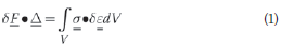
where δ stands for "variation in" and refers to the virtual load-displacement system, F is the virtual point force, is the actual displacement where the virtual force is applied,
  is the stress in the real solid and
  is the virtual strain. Integration is performed over the entire volume, V, of the solid.
In structural mechanics, where the solid in eq (1) consists of structural members, and for a unit virtual load, eq (1) becomes:
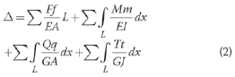
The structure's deflection is at the point of application and in the direction of the virtual unit load. The small letters, f, q, m and t refer to the virtual system's internal axial forces, shear forces, bending moments and torsional moments, respectively. The capital letters, F, Q, M and T refer to the real system's internal axial forces, shear forces, bending moments and torsional moments, respectively. Integration is performed over the length, L, of each member. Summation occurs over all members in the structure. The material and geometric section properties can vary along the length of the members and are: the Young's modulus, E, the shear modulus, G, the cross-sectional area, A, the 2nd moment of area, I, and the polar 2nd moment of area, J.
Equation (2) can be viewed as a summation:
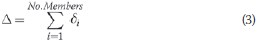
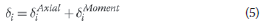
where δi is the deflection contribution of member i to the overall structural deflection
 The magnitude of the contribution is related to the amount of strain energy in the member.
If only two-dimensional plane frames or trusses are considered and shear deformation is neglected, then:
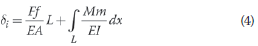
or
Note that shear deformation is neglected because it is usually small compared with other terms, especially in steel structures.
In this paper, only eqs (3), (4) and (5) are used, with the associated assumptions and limitations.
THE VIRTUAL WORK OPTIMISATION METHOD(VWOM)
The VWOM finds the structure of minimum mass for a given structural member configuration by selecting member sections that satisfy the strength and global deflection requirements. In structural design, the global deflection is an input parameter, often specified as a fraction of the structure's span or height. Not only is the magnitude of the global deflection required, but also the direction. The virtual unit point load is then placed at the point where the deflection is to be met in the direction of interest.
Whenever the internal forces or the global deflection are required, the standard stiffness matrix method is used in the VWOM. Most modern structures programs use this matrix method. It must be noted that the VWOM can use any method that computes the internal forces and deflections within the structure. In this paper, whenever global deflection or internal forces are required, the commercial package Prokon (2008) is used.
The VWOM is an iterative method. Although the iteration can start off assuming any section for each member, a more logical approach is to design each member to meet the strength requirements.
SATISFYING THE STRENGTH REQUIREMENTS
In the first iteration the members are chosen such that they satisfy the strength requirements. These are specified in building codes and here the South African structural steel code, SANS 0162-1 (2005) is used. The internal forces within each member are checked against the code's requirements.
The initial member selection for strength requires its own iteration for statically indeterminate structures. This is due to the fact that as member sections are changed, the internal forces within them change. The lightest section satisfying the strength requirements is chosen for each member. If members are grouped into a set, then the section chosen for the set will be the lightest section satisfying the strength requirement of every member in that set. For a general structure, perfect convergence of the strength iteration might not be achievable (i.e. achieving the lightest structure in which each member satisfies the strength criterion). Rather, several member sections can oscillate between possible solutions as the iteration continues. This occurs due to the force redistribution as the member sections change. The oscillations might indicate an instability in the search or multiple possible solutions. If a stable solution has not been achieved after a predefined number of oscillations, the iteration is stopped. It must be pointed out that the oscillation that might occur when satisfying the strength criterion is of little importance since any one of these solutions is only the starting point for the optimisation algorithm.
The ultimate load cases are used in the strength calculations; serviceability loads are used to check the deflection criteria. In some cases, the deflection criterion is met as soon as the strength requirement is satisfied. This is unusual for steel structures with long spans.
MEETING DEFLECTION CRITERIA AND OPTIMISING THE STRUCTURE
The first step in the optimisation iteration process (i.e. minimising the structure's overall mass) is to determine the contribution of each member to the total deflection at the chosen point. The member's deflection contribution is calculated using eq (4) and the total deflection by eq (3). The internal forces due to the real and virtual load systems are calculated using any standard method or commercial software.
It is now assumed that the geometric sectional properties (the 2nd moment of area, I, and the cross-sectional area, A) have a linear relationship with the member's deflection contribution. Thus considering member i, with its current properties and deflection, designated as (old) and utilising new sectional properties called (new), the predicted deflection contribution is:
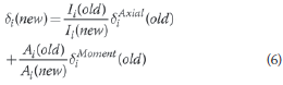
For statically determinate structures this assumption is exact. For indeterminate structures the accuracy of the prediction depends on the ratios  and
and  how far they are from unity. See the section "A note on increment size" for a brief discussion.
Two main questions arise:
1. Which member has to be changed?
2. By how much must the member be changed?
To answer these questions, eq (7) is used to determine the efficiency of changing the sectional properties of member i. The efficiency of the change is defined as the change in the member's deflection contribution versus the increase in the member's mass, mi, i.e.
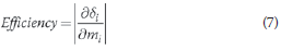
or in finite difference form:
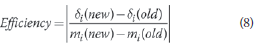
Eqs (7) and (8) give a rational basis for choosing which member within a structure has to be changed and by how much. The efficiency of each cross-section that is available from a database (e.g. the Southern African steel construction handbook (2005) or The Red Book), for each member in the structure, can be computed. (Restrictions, such as selecting member changes from only one type of section, e.g. selecting new sections only from angle irons, can be enforced.) The most efficient section change, or the highest value in eq (8), is now made. This completes the current iteration in the optimisation process.
Any section database can be used with the VWOM. Furthermore, the database can be augmented with custom sections. As the size of the database increases, so too does the computational cost. In the VWOM, since only eqs (6) and (8) have to be evaluated for new section sizes, the computational cost is linearly proportional to the size of the database. Contrast this with most other optimisation methods in which the computational cost increases exponentially (Gutkowski et al 2006).
The iteration is continued until the deflection criterion, or target, is about to be met. In the last iteration, the section with the lowest mass increase which reaches the target deflection, and not necessarily the most efficient section, is chosen. This prevents deflection being reduced below the target.
It must be pointed out that the deflection contribution of a member (eq (4)) to the overall deflection can be negative. This occurs when the internal forces due to the real and virtual loading systems have opposite effects. In such a case, the member is designed to satisfy the strength requirement only.
Within each iteration the strength of each member is checked since section changes cause internal force redistribution. If required, the member size is adjusted to meet the strength requirement. At the end of the iteration, each member satisfies the strength requirement and the overall structure is closer to meeting the deflection criterion.
The optimisation curve
The optimisation curve is obtained at the end of each iteration by plotting the overall deflection of the node of interest versus the structure's mass. An idealised optimisation curve is shown in Figure 1.
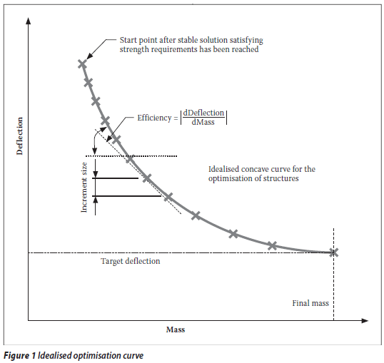
Note that "efficiency" is defined as the absolute value of the slope of the optimisation curve. As the optimisation curve shows, as the structure is stiffened, it becomes increasingly difficult to reduce the deflection, i.e. a greater mass increase is required per unit deflection decrease, or the efficiency decreases.
In reality, with discrete sections and a finite number of sections available, the idealised curve in Figure 1 would not be smooth. The discrete nature of the section distribution and the requirement for the member to meet certain strength criteria lead to overdesign of the members to some degree. If strength criteria were not enforced (or were not critical), the optimisation curve would be smooth.
The initial members' section choices, or the starting point of the optimisation, have little influence on the final structure reached. Members that are initially overdesigned for strength are reduced in subsequent iterations both by the strength function and by the efficiency iteration.
A note on increment size
In eq (6), any (new) section properties can be chosen. The larger the (new) section with respect to the current iteration (old) properties, the larger the change in the deflection contribution. Larger deflection increment sizes lead to fewer iterations and hence faster attainment of the target deflection. However, as the deflection change increases, so the assumption of eq (6) for indeterminate structures becomes less valid, and this could lead to non-smooth and oscillatory optimisation curves. Although more research is required to determine the optimal size of the deflection change increment, it has been found that increments of 1 mm (per iteration) produce consistent optimisation curves. Please note that the reduction in deflection contribution can only be a target since the section properties correspond to a finite database and are discrete in nature. Throughout this paper, the target deflection increment is set to 1 mm; for comparison purposes, larger target increments of 10 and 20 mm are investigated.
A note on member groups
One factor greatly affecting the optimised mass is how many different sections there are in a structure. In practice, the economy of the structure (i.e. having as many sections as required) is weighed up against the constructability and simplicity of the design. Members with the same sectional properties in a structure are grouped into sets. Structures with fewer groups will generally be heavier and many members will be larger than needed. The forced grouping of members imposes constraints on the optimisation process.
The VWOM can be applied directly when the optimisation is constrained by forcing members to belong to groups. When groups are present, it is required that:
the efficiency search (eq (8)) is performed for the whole group, and
In the above procedure, the members belonging to groups or sets are specified at the start of the optimisation. The VWOM can also be used to determine the most efficient member groupings, but this will be the topic of future research.
CASE STUDIES
To demonstrate the VWOM, the optimisations of three different case studies are considered: (i) a benchmark ten-member truss; (ii) a truss frame that has been designed by a professional engineering company; and (iii) a tall structure. Wherever possible, the results are compared with published or obtained solutions. The case studies are solved using the VWOM assuming (a) no member grouping, (b) the same grouping as in the solution with which a comparison is being made, and (c) efficient grouping of members.
TEN-MEMBER BENCHMARK TRUSS
The ten-member truss in Figure 2 is a standard benchmark structure used to test optimisation methods. This structure has been optimised previously by authors such as Gutkowski et al (2006) and Haug & Arora (1979). In Figure 2 the numbers indicate the node and element numbers. All the members have the following material properties: the stress is limited to 172,4 MPa, the Young's modulus is E = 68,95 GPa, and the density is ρ = 2 767,9 kg/m3. In this standard problem the load is set to P = 445 kN. Each member in the truss can support only an axial load.
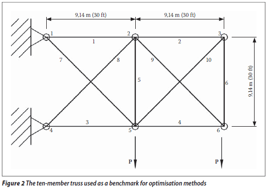
The vertical deflection of node 6 is limited to the target value of 50,8 mm (after Haug & Arora 1979).
A database containing 61 sections was created, with areas ranging from 64,55 mm2 (0,1 in2) to 19 419 mm2 (30 in2) in increments of 322,6 mm2 (0,5 in2) (after Gutkowski et al 2006).
This benchmark problem was analysed using the VWOM and the computed optimisation curves with target deflection increments of 1, 10 and 20 mm are shown in Figure 3. The VWOM is compared with the "effective discrete method" (EDM) of Gutkowski et al (2006), and the "continuous cross-sectional area" (CSA) of Haug & Arora (1979). The latter reference assumes an infinite number of possible cross-sections, whereas the VWOM and the EDM can select from a more realistic, finite database of sections as above. The results from these methods are summarised in Table 1.
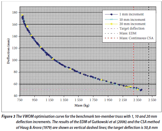
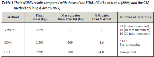
Table 1 and Figure 3 show that the VWOM produces a solution that is 4,6% lighter than that of the EDM of Gutkowski et al (2006). The number of iterations required to reach the solution is also significantly less. The VWOM solution is 4% heavier than the CSA solution due to the fact that Haug & Arora (1979) are not restricted to selecting from a finite discrete database of cross-sections.
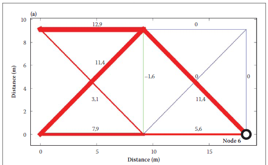
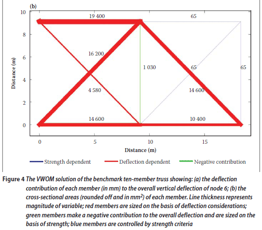
As can be seen in Figure 3, the different increments of target deflection produce optimum solutions within 1% of each other. As mentioned above, for statically determinate structures, the solution is independent of deflection increment size. The benchmark structure that is indeterminate initially tends to be statically determinate as the optimisation process continues, with members 2, 6 and 10 being reduced in size until they contribute negligibly to the overall strength and deflections of the structure. This is demonstrated in Figure 4(a) which reports the deflection contribution of each member to the vertical deflection of node 6. The line thickness represents the contribution of the member to the overall deflection of node 6. Figure 4(b) gives the cross-sectional area of each member in mm2. Here the line thickness is proportional to the cross-sectional areas of the members. In Figure 4, as in the rest of the paper, the colour scheme is as follows: members in red had their section sizes altered to satisfy the deflection criterion; green members make a negative contribution to the overall deflection and their size is determined by the strength requirements; members shown in blue are sized on the basis of strength criteria only.
TRUSS FRAME
To test the automated VWOM, the truss frame shown in Figure 5, which was designed by a firm of professional engineers to comply with the SANS 10162-1 (2005) code, is considered. All members were made of 350W steel, and the loading is W = 6,81 kN. Note that the structure is not perfectly symmetrical.
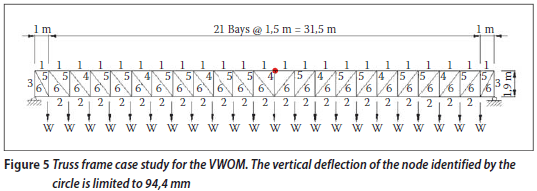
The effective length factor for internal members was taken as 0,85, consistent with that of the professional engineers. The engineers specified the top and bottom chords, as well as every third vertical member, as channel sections. The remaining members are angle irons. The group to which each member belongs is specified by a number in Figure 5. The maximum deflection occurs approximately at mid-span, at the node identified by the circle (94,4 mm). This deflection meets the code requirements of l/350.
The VWOM was used with the groups in Figure 5 and with the same section-type restriction as in the original design. In addition, the optimisation was performed assuming no member grouping, i.e. each member can have its own section. The members were modelled as beam elements, i.e. bending and axial deformation is allowed. Figure 6 plots the optimisation curves and the design solution. The numerical results are presented in Table 2.
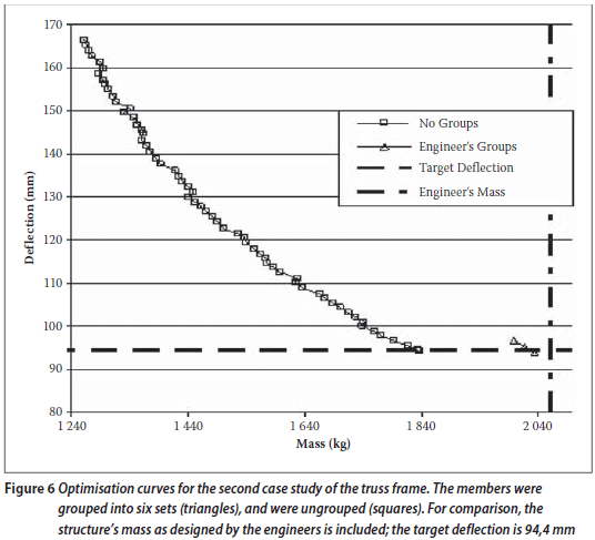
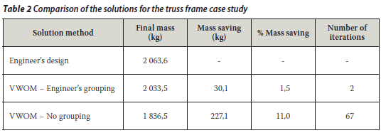
Table 2 shows that if the same groupings and section-type constraints as in the engineers' design are used, the VWOM produces a solution that is 1,5% lighter. If the members are not grouped, then the VWOM's solution is 11,0% lighter. It is interesting to note that the VWOM, which can be automated, produces solutions that are slightly better than those of professional engineers.
Deflection increments of 1 mm were used to produce the optimised solutions. Larger increments of 10 and 20 mm yield answers within 0,5% of the 1 mm increment solution. This is due to the fact that although the structure is a truss frame, the geometry and loading configuration ensure that it is in effect a statically determinate truss.
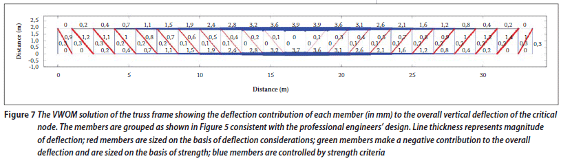
Figure 7 plots the contribution of each member in the optimised structure, in contrast with the professional engineers' member groupings shown in Figure 5, to the vertical deflection at the critical node. The section sizes are determined by the strength requirements (identified in blue) for all members except the diagonals. Hence significant optimisation is not possible.
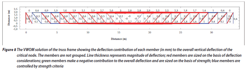
The contribution of each member to the vertical deflection of the critical node when the members are not grouped together is shown in Figure 8. Most sections are now determined by deflection criteria (identified in red), allowing for better optimisation.
Comparing the solutions with and without (Figure 7 to 8) member grouping suggests a more efficient grouping scheme. For example, adding just two more groups to those in Figure 5 leads to an optimised structure that is 10,3% lighter. This saving is close to the 11,0% achieved when there are no groups at all! The two groups that are introduced are: the inner and outer four bays of the top chord; and the inner and outer six bays of the bottom chord. How the VWOM can be used to group members efficiently is a topic for future research.
MULTI-STOREY BUILDING
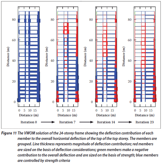
The indeterminate multi-storey (24-storey) frame designed by Davison & Adams (1974), shown in Figure 9, is used as the third case study for the VWOM. The serviceability loads and the design parameters are presented in Figure 9 in which fy is the yield stress, E is the Young's modulus, and Kx and Ky are the effective length factors. The target horizontal deflection is limited to 1/300 of the height of the building. The numbers next to the members represent the groups used by Davison & Adams (1974). Since this is a tall structure, the dominant deformation is horizontal, and the vertical deflection was not checked by the references cited below nor will it be considered by the VWOM.
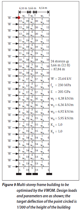
The results of the VWOM are compared with the work of both Saka & Kameshki (1998), who used the hybrid genetic algorithm (HGA), and Camp et al (2005), who used the ant colony optimisation (ACO) method. The former researchers used the British standard BS5950 (1995), while the latter employed the United States load and resistance factor design (LRFD) (AISI 2001). The present VWOM uses the South African SANS 10162-1 (2005) code. Each member in the multi-storey frame is modelled as a beam that can deform axially and in bending.
A comparison of the VWOM results with those of the other methods is shown in Table 3. The base case is the VWOM using the member groups of the original design shown in Figure 9. The optimisation curves with and without groupings are shown in Figure 10.
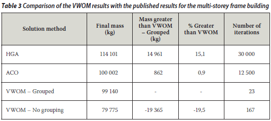
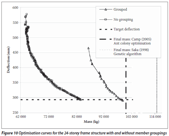
Table 3 and Figure 10 show that the VWOM with member grouping produces a solution that is 0,9% lighter than that of Camp et al (2005) and 15,1% lighter than that of Saka & Kameshki (1998). Since not all the design parameters used in the various methods were published and different design codes were adhered to, it can be argued that the VWOM produces results similar to those of the ACO and better than those of the HGA. However, the number of iterations required by the VWOM is three orders of magnitude less than in the other methods. Hence the VWOM is significantly less computationally expensive. Moreover, if the members are not grouped (i.e. if each member has a unique section) in the VWOM, a further 19,5% mass saving is realised.
For the member grouped case, Figure 11 shows the contribution of each member to the overall horizontal deflection of the top of the top storey. Iteration 0 starts off with each member satisfying the strength criteria (members in blue). As the iterations progress, more and more members are governed by deflection considerations (depicted in red). When the VWOM solution has been reached (iteration 23), the member sections are tailored and the contributions to the overall deflection increase as the supports are approached.
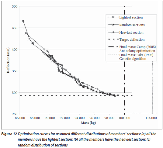
Effect of initial member sections
The VWOM applied to the 24-storey frame, with member groupings, assumed three different initial distributions of members' sections: (i) every member having the lightest section in the database; (ii) every member having the heaviest section in the database; and (iii) a random mixture of sections from the database. The first point of the optimisation curve shown in Figure 12 is plotted only after all the strength requirements have been satisfied. As can be seen in Figure 12, the path of the optimisation curve depends on the starting point, but the solutions converge to within 0,4% of each other.
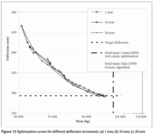
Effect of deflection increment size
Figure 13 plots the optimisation curve for the 24-storey frame assuming three different deflection target increments, namely 1, 10 and 20 mm. The members are grouped as shown in Figure 9. Since the structure is statically indeterminate, the target deflection increment does affect the optimisation curve. If the increment is small enough, the final results are close to each other. For the three increment sizes considered, the optimisation curves follow a similar broad path and the results are within 0,9% of each other. The structure's indeterminacy produces non-smooth curves with force redistribution occurring after each iteration.
CONCLUSION
In this paper the well-known principle of virtual work was used as the framework for optimising a structure with a given geometry and loading. The Virtual Work Optimisation Method (VWOM) that was developed was used to find the lightest structure that meets a prescribed deflection. Although the design of the members of a structure for strength can easily be automated to meet building code specifications, to enforce deflection criteria requires the experience of an engineer. The VWOM can be used to automate not only the strength but also the deflection requirements.
The VWOM was used for three case studies: (i) the benchmark optimisation ten-member truss; (ii) a truss frame designed by professional engineers; and (iii) a 24-storey frame. In all cases the VWOM produced solutions that were at least as efficient as those of other, published methods. In some cases the VWOM answers were significantly more economical. The computational effort (and hence time) required by the VWOM was less than that of the methods reported in the literature, requiring orders of magnitude fewer iterations to converge.
The optimisation can be constrained by grouping members into sets and requiring that all members in a given set have the same sectional properties. In practice, members are grouped together in order to simplify the design and the construction process. Allowance for member groups was incorporated into the VWOM. As expected, the constraint of grouping members together produced structures that were heavier than when each member was allowed to have its own unique section.
Future research on the VWOM will focus on the following areas:
ACKNOWLEDGEMENT
The authors would like to thank Mr Spencer Erling of the Southern African Institute of Steel Construction for his helpful comments and suggestions.
REFERENCES
AISI (American Iron and Steel Institute) 2001. North American specification for the design of cold-formed steel structural members. Washington D.C. [ Links ]
BS5950 1995. Structural use of steelwork in building. British Standards Institution. [ Links ]
Camp, C V, Bichon, B J & Stovall, S P 2005. Design of steel frames using ant colony optimization. J Struct Div, ASCE, 131(3): 369-379 [ Links ]
Davison, J H & Adams, P F 1974. Stability of braced and unbraced frames. J Struct Div, ASCE, 100(2): 319-334. [ Links ]
Erbatur, F, Hasançebi, O, Tütüncü, I & Kiliç, H 2009. Optimal design of planar frames with genetic algorithms. Computers and Structures, 75: 209-224 [ Links ]
Gutkowski, W, Bauer J & Zawidzka, J 2006. An effective method for discrete structural optimisation. Engng Comp, 17(4): 417-426. [ Links ]
Haug, E J & Arora, J S 1979. Applied optimal design, New York: Wiley. [ Links ]
Kargahi, M, Anderson, J C & Dessouky, M M 2006. Structural weight optimization of frames using tabu search. I: Optimization procedure. J Struct Engng, ASCE, 132(12): 1858-1868. [ Links ]
Mahachi, J 2004. Design of structural steelwork to SANS 10162. CSIR Built Environment, Pretoria. [ Links ]
Prokon Software Consultants Ltd 2008. Prokon software. [ Links ]
SAISC 2005. Southern African steel construction handbook, 5th edition, "The Red Book". Southern African Institute of Steel Construction. [ Links ]
Saka, M P & Kameshki, E S 1998. Optimum design of multi-storey sway steel frames to BS 5950 using a genetic algorithm. In: B H V Topping (Ed) Advances in engineering computational technology, Civil-Comp Press, pp 135-141. [ Links ]
SANS 10162-1: 2005. The structural use of steel. Part 1: Limit-states design of hot-rolled steelwork. South African National Standard. [ Links ]
 | PROF ALEX ELVIN graduated from the Department of Civil Engineering, University of the Witwatersrand in 1989. He completed his Master's in 1991 and his PhD in 1996, both at the Massachusetts Institute of Technology (MIT). He has worked in industry and taught several classes at MIT. He was a junior faculty member at Harvard Medical School from 1998 to 2002 doing finite element analysis of implants. Since 2007 he has been an Associate Professor in Structural Mechanics at the University of the Witwatersrand. His research interests are focused on theoretical (numerical) modelling of SMART materials, instrumentation and sensor networks in engineering, health monitoring of structures and problems in optimisation. |
 | RICHARD WALLS completed his BSc at the University of the Witwatersrand in 2008. He is currently completing an MSc in structural engineering and a Graduate Diploma in Engineering (GDE) at the School of Civil and Environmental Engineering at the University of the Witwatersrand. He holds a bursary from BSM Baker. |
 | DANIEL CROMBERGE graduated from the University of the Witwatersrand in 2008 with a BSc (Civil Engineering). He was a bursary student with Jeffares and Green (Pty) Ltd. He is currently working as a traffic engineer at Transportation and Traffic Technology (TTT) Africa. |
 Contact details:
School of Civil and Environmental Engineering University of the Witwatersrand
Johannesburg
T: 011 717 7145; F: 011 717 7045
alex.elvin@wits.ac.za
Contact details:
School of Civil and Environmental Engineering University of the Witwatersrand
Johannesburg
T: 011 888 5507; C: 072 372 4096
richardwalls28@gmail.com
Contact details:
TTT Africa (Pty) Ltd
37 Sunninghill Office Park
Sunninghill Johannesburg
T: 011 807 8016; F: 011 807 1607
cromberged@tttafrica.co.za

