


Services on Demand
Article
 English (pdf)
 Article in xml format
 Article references
Indicators

Related links
-
 Cited by Google
 -
 Similars in Google
Share

 Permalink
Journal of the South African Institution of Civil Engineering
On-line version ISSN 2309-8775
Print version ISSN 1021-2019
J. S. Afr. Inst. Civ. Eng. vol.51 n.1 Midrand Apr. 2009
TECHNICAL PAPER
Public standpipe design and maintenance for rural South Africa
J Haarhoff; L Rietveld
ABSTRACT
The public standpipe is the user interface of most rural water systems in South Africa. Despite the renewed focus on providing safe water for all South Africans, field surveys throughout the country show that public standpipes are generally in a deplorable condition. As these standpipes contribute only about 1% or less to the overall cost of rural water-supply systems, this paper argues that the public standpipe deserves more engineering attention during design, construction and maintenance, without having a significant cost implication. The paper systematically lists the relatively simple design considerations, with quantitative guidelines where applicable, and gives multiple illustrations of common mistakes encountered during three field surveys conducted in the Venda region during 2006, 2007 and 2008.
Keywords: Standpipe, Venda, water supply, tap, design, maintenance
INTRODUCTION
As South Africa is facing up to the challenge posed by the Millennium Development Goal to halve the number of people who lack access to safe drinking water, the minds of water-supply authorities, designers and operators are, understandably, occupied largely by the selection of dependable water sources, boreholes, treatment plants, pump stations, storage tanks and pipelines - those expensive items that require a high degree of engineering input. From the all-important perspective of the average consumer, however, these items are largely invisible. The users base their entire perception of water supply on the proximity, convenience and safety of the simple public standpipe, which is the user interface of many South African rural water-supply systems. It is surprising, therefore, to find an almost complete lack of detailed design guidelines for standpipes. Even more worrying is the poor state of public standpipes in most rural areas, caused by a lack of proper design, poor construction or neglected maintenance.
This paper makes some suggestions towards the improved design of public standpipes. It will systematically enume rate the many, often straightforward factors that determine the eventual level of service provided by the public standpipe. The factors will be illustrated by the results of an exhaustive survey of more than 100 standpipes in 21 Venda villages in the Upper Nwanedi basin. From this, a number of quantitative guidelines will become evident. Finally, it will be shown that significant improvements can be made to standpipe design with a negligible impact on the overall cost of rural water-supply systems.
EXISTING SOUTH AFRICAN DESIGN GUIDELINES
The most recent set of South African design guidelines for rural water-supply systems are those published by the South African Department of Water Affairs and Forestry in 2004 (DWAF 2004), which offer only a few points pertaining specifically to standpipe design:
Standpipes should be a maximum walking distance of 200 m from the home.
FIELD SURVEY OF STANDPIPES
A field survey was made of 21 villages in the Upper Nwanedi basin during October 2007. These villages now fall under the jurisdiction of the Mutale Local Municipality, which forms part of the Vhembe District Municipality. The villages all fall within the catchment area of the Nwanedi and Luphephe Dams. In total, there were 1 557 households, with the smallest village having 10 households and the largest 176 households. Previous fieldwork (Jagals 2008) established that there was an average of 5,8 persons per household, bringing the total population within these villages to 9 030. There were 104 standpipes in total, bringing the average number of households served by each standpipe to 15. There were large discrepancies between the villages - this number ranged from as low as four households per standpipe to more than 30 households per standpipe. The total areal footprint of the villages was 6,2 ha, which amounts to an average population density of 1 455 people per ha and an average standpipe density of 17 taps per ha. The total length of pipes in these systems is 29,4 km, resulting in an average of one standpipe for every 283 m of pipe. The typical per capita water use, as established by fieldwork during the preceding three years, is an average of about 22 litres per capita per day (Sterk 2006). The oldest parts of some systems were about 10 years old and the newest systems had just been commissioned, with an estimated average age of about three years.
The position of each standpipe was noted with a GPS (global positioning system), a photograph was taken and the general positioning of the standpipe was noted in relation to the topography and the proximity of trees. The flow rate was measured with a calibrated bucket and a stopwatch, while the water quality was observed for colour, excessive turbidity or trapped air. Finally, the tap height and platform size were measured by tape. Only those measurements relevant to this paper have been described. The complete survey also included interviews and laboratory analyses to allow an assessment of the entire water system, which has been reported elsewhere (Rietveld et al 2008).
INDIVIDUAL ELEMENTS OF STANDPIPE DESIGN
Standpipe position
Two aspects of standpipe positioning are deemed to be of importance. Firstly, given the frequent presence of people waiting in line, doing their laundry or simply socialising at the standpipes, a standpipe located in the shade would add to the comfort of the users. This consideration was not taken into account to any significant extent in the design phase - the survey showed that 94% of the standpipes were completely out in the open, 3% were partially shaded and only 3% were completely in the shade, despite the presence of fairly large trees in most of the villages.
Secondly, when the standpipe is in undulating terrain, the designer has to reconcile two conflicting preferences:
During the field survey, it was found that 21% of the standpipes were in areas with a gradual slope in one direction. In such cases, where there is no option other than to place the standpipes on the slope, the designer should place them at a level higher than the homes served to ease the burden of carrying the filled containers. Where the designer had had the choice of placing the standpipes either at the high or the low points along the pipeline profile, 20% of the standpipes were inconveniently placed at the low points and the other 80% correctly placed at the high points.
The standpipe platform
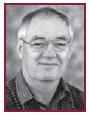
It is absolutely vital to ensure that there is a firm, unobstructed footing in the area immediately around the standpipe. Slipping or stumbling with heavy loads will lead to injury, especially when body, head and eye movements are restricted by these loads being balanced on the head. The minimum requirement is a level, secure concrete platform below the tap to ensure a proper foothold and to prevent a muddy quagmire. In addition, the platform must be large enough to allow all lifting and turning movements before the person steps off the platform. A number of bad examples are shown in Figure 1.
The standpipe platforms for single taps, where they were provided, had sizes ranging from 0,70 by 0,75 m = 0,53 m2 to 1,2 by 1,2 = 1,44 m2. The standpipe supports were placed mostly to the one side, close to the edge of the platforms. The platforms for double taps were all 1,0 by 2,0 m = 2,0 m2 with the standpipe support in the centre of the platform. In general, a platform area of about 1 m2 per tap is provided.
The platform height is defined as the difference between the level of the platform on which the container is placed for filling and the level of the surrounding ground immediately next to the platform. It goes without saying that the platform height must be such as to allow the safe and unhindered movement of the user and the container onto and away from the platform. Such freedom of movement is often restricted by misguided design attempts in the form of little walls to contain the spilled water - a point returned to later when the need for adequate drainage is discussed. The following considerations are important:
A note is warranted about the structural stability of the standpipe platforms. When the standpipes are installed in undulating terrain, the flow of storm water will tend to scour away the natural ground next to the platform. If the platforms are formed by pouring thin concrete slabs on the ground, the edges of the slabs will be rapidly exposed and undercut, and will eventually break away. Concrete downstands at the edges, projecting well below ground level, will prevent erosion of the soil below the platform.
The standpipe support
The standpipe support column has to provide the rigidity to keep the standpipe upright. Standpipes are subject to severe lateral loads, imposed by being bumped into by heaving containers, wheelbarrows, humans and animals. To prevent damage to the water main and the plumbing leading to the taps, it is important to guarantee a sturdy support even if the area around the standpipe is completely waterlogged due to a broken tap or heavy rains.
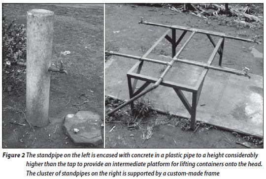
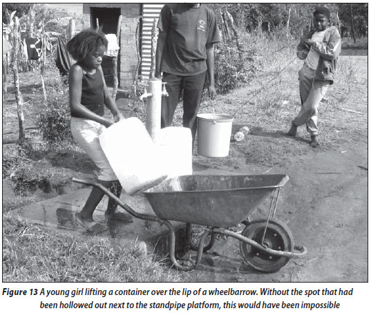
The most common support system for the newer water systems takes the form of the vertical water pipe of galvanised steel being encased in a PVC pipe filled with concrete. The plastic pipe generally has an outside diameter of 150 mm, but some supports also employ a smaller diameter of 90 mm. In some cases, the pipe support is continued some distance beyond the height of the tap, with the top of the infill concrete being rounded and smoothed to provide an intermediate platform for lifting the containers onto the head. Examples are shown in Figure 2. The field survey showed that the dominant design used for 80% of the surveyed taps is the concrete-filled PVC pipe. This seems to be universally applied to new contracts.
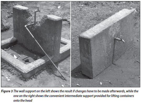
Another support used for older systems takes the form of a support wall, examples of which are shown in Figure 3. The principal weakness of this design, sturdy as it may be, is that it is quite inflexible if repairs or additional connections are required at a later date. The wall then has to be partly demolished to gain access to the supply pipe for further connections. (The same drawback applies to the concrete-filled pipes, but here it is much easier to remove the pipe completely and replace it with a new one.) Some of these walls are also continued beyond the height of the taps to provide a comfortable intermediate platform for lifting containers onto the head. Support walls, used for 9% of the taps, were built about a decade ago and seemed to have fallen out of favour in recent years.
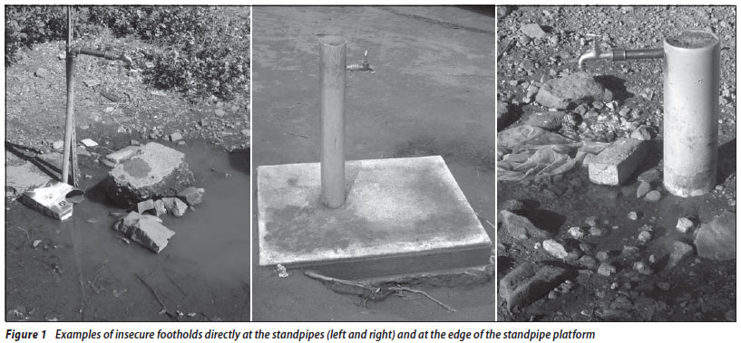
A few cases were encountered where makeshift supports were used, presumably when standpipes had been added or moved after the original systems had been built. In 5% of the cases the taps were supported by steel spikes (often bent or displaced from the vertical) and in 6% of the cases no supports were provided at all. These, examples of which are shown in Figure 4, are clearly unsatisfactory.
Tap height above platform
The tap height is defined as the clear vertical distance between the top of the platform and the tip of the tap. The ideal tap height is constrained between the following limits:
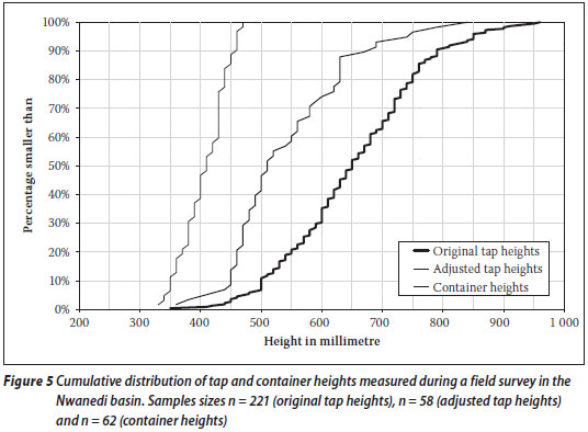
The primary driver for the tap height is the height of the containers used. The containers that are almost exclusively used are industrial plastic containers. These have a screw-cap on top and volumes ranging from 20 to 25 litres, and have found their way from commercial use in cities and towns to the rural areas. These containers are designed to be handled by adult working men and are certainly not the optimal size for long-distance water hauling by women and children. Novel new designs, such as the HIPPO water roller, have been introduced, but the sad fact is that the vast majority of containers in use remain the industrial containers and this situation is likely to continue in the foreseeable future. A number of containers used in the Venda region were randomly surveyed during October 2008 (n = 62) and their cumulative distribution is shown in Figure 5.
The use of hosetails warrants special mention. Two types of hosetail need to be distinguished:
The tap heights of the originally constructed standpipes were measured during two field surveys done in Venda during October 2007 and October 2008 (the surveys were done in different areas). The cumulative distribution of the pooled data set is shown in Figure 5.
A striking feature of Figure 5 is the extremely wide scatter in the tap heights as they were originally constructed. This points either to a wide range of preferred heights by different designers, or more probably to poor specification and construction control. Moreover, the original tap heights as constructed are significantly higher than the ideal height estimated above. The median of the tap heights is 650 mm, 240 mm more than the median container height and 180 mm more than the maximum container height.
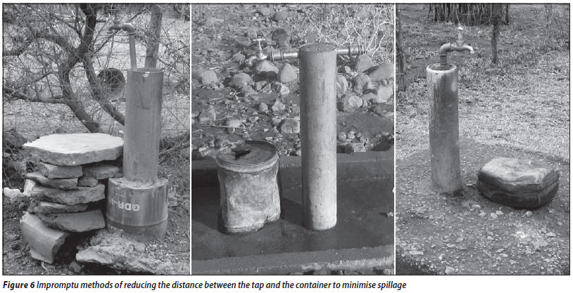
This large discrepancy has forced many villagers to take matters into their own hands and to build a small makeshift platform with stones or bricks directly under the tap, on top of the original platform, as shown in Figure 6. Where these cases were encountered, the adjusted tap heights from the makeshift platforms were measured; the cumulative distribution is also depicted in Figure 5. In this case, the median height is 510 mm, only 100 mm more than the median container height and 40 mm higher than the maximum container height.
Based on the above findings, a guideline tap height of between 500 mm and 550 mm is proposed.
Tap details, specification and maintenance
The tap is the most crucial component of the standpipe installation. It has to be exceptionally robust to withstand the high wear and tear due to frequent daily use, occasional abuse and, inevitably, some vandalism. It is therefore essential to start off with a tap of only the highest quality. But, regardless of how good the tap is, its lifetime will be considerably less than the lifetimes of most of the other elements of rural supply systems. Therefore, it is of equal importance to have a systematic procedure for tap maintenance and replacement.
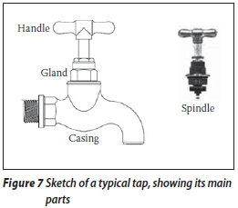
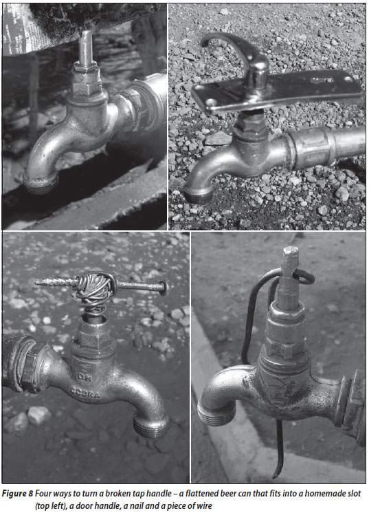
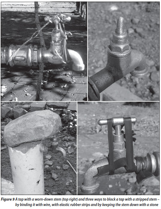
The quality and condition of the taps surveyed were generally unsatisfactory. A tap is a simple device with only one moving part, namely a valve spindle that is screwed up and down by hand to open or block the water passage - see Figure 7. At the top of the spindle is a handle to allow the spindle to be turned, while the valve spindle has two seals - a gland seal at the top to prevent water from pushing past the spindle when the valve is open, and a washer at the bottom which blocks the water passage when the valve is closed. All possible problems were observed - handles were broken, the thread on the valve spindles was stripped, the gland seals were leaking and the sealing washers were worn. The first two problems render the standpipes unusable and leave consumers completely without water. Figures 8 and 9 show examples of these tap failures, together with ingenious "repairs" effected by villagers with no tools, spares or training. The latter two problems, while still leaving the taps operational, lead to excessive water loss.
The collected field data are evidence of the severe conditions under which the average village tap has to operate. In the study area, there are 9 030 people, each using about one container of water per day. With the median flow rate from the taps of about 0,55 litres per second, it takes about a minute to fill a container. The average tap is therefore used to fill containers for about 87 minutes per day, or 15% of a 10-hour day. To fill the containers, each of the 104 taps therefore has to be opened and closed 9 030/104 = 87 times per day. Added to this, there is the burden of laundry being done directly at the tap, plus the drinking of water of passers-by (notably school children). If every person opens a tap once a day (in addition to the containers being filled), each tap is used about 170 times per day, or 62 000 openings per year.
The specification of taps with metallic bodies should be informed by the South African National Standard (SANS 226: 2004). However, many of the taps encountered during the field survey were imported taps which do not comply, or have not even bothered to attempt to comply with the SANS standard. SANS 226 states that the spindle, including its cross-member, should be able to withstand a torque of 10 Nm. (Previously, the standard specified the diameter of the spindle rather then the limiting torque.) This is an important criterion as most of the tap failures had to do with broken handles or stripped threads. The spindle itself should be able to resist a bending moment of 15 Nm without any damage to the spindle and the washer. This criterion seems less important as only one tap was found with a bent spindle. Finally, the tap should be able to withstand, without leaking, 3 000 opening/closing cycles under a strong torque of 4 Nm (a rapid test for washer integrity) and 100 000 cycles under a light torque of 1,5 Nm (to approximate the wear and tear during normal use). The last part of the specification, incidentally, constitutes a relaxation of the early editions of the standard; before 1987, 200 000 cycles were specified under light torque (Coetzee 2008). For taps that do meet the SANS specification, the current specification implies a lifetime for the average village tap of 100 000/62 000 = 19 months, whereas the previous specification suggested a lifetime of three years.
Some comments are warranted about the local maintenance programme, as observed and gleaned from interviews with the staff involved. (Although this reflects a policy at one specific location, there is good reason to believe that similar procedures are commonly applied throughout South Africa.) The replacement of taps is fully reactive. Taps that are completely broken or unable to be closed due to stripped valve spindles are reported and replaced by a tap fitter. Taps are completely removed and replaced with new taps. The new taps are periodically supplied in small batches from a remote depot of the local municipality. Broken taps are returned and their eventual destiny could not be traced. The new taps at the depot, in turn, are purchased through a tender procedure administered by the district municipality. The fitters and superintendent at local level expressed their strong dissatisfaction with the poor quality of the taps supplied, reportedly selected exclusively on the basis of lowest price, without consideration of their previous practical performance and quality.
From the above, three self-evident suggestions follow:
Collection, diversion and use of spilled water
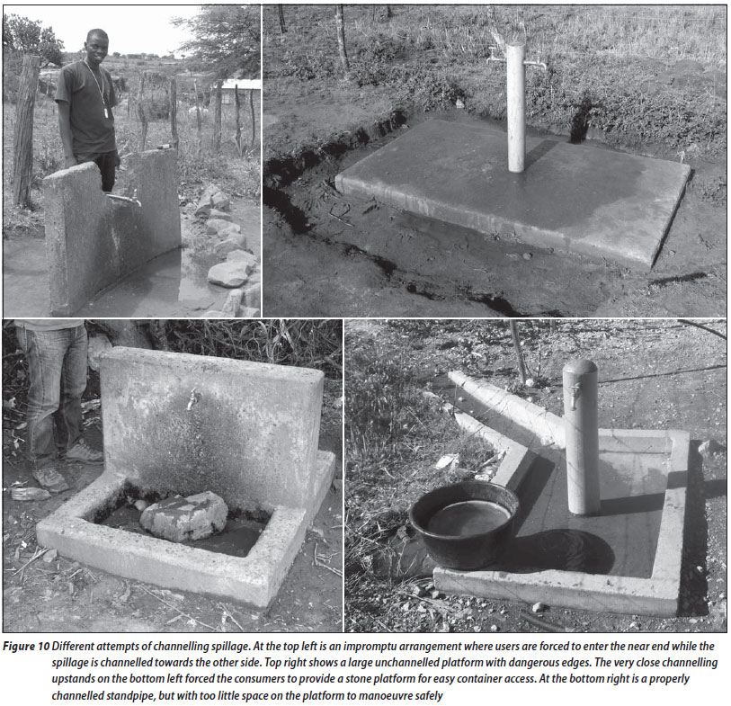
Spillage at a standpipe is inevitable. If it is simply left to drain off the platform, it will erode the natural ground immediately next to the platform and, in time, produce a hazard for those having to step off the platform with heavy loads. For this reason, some attempts have been made to contain the spillage and to direct it away from the platform in a controlled manner. Some examples are shown in Figure 10.
The use of small upstands on the edge of small platforms is to be completely avoided. Not only do they impede the positioning of the container under the standpipe, but they pose the likely danger of being tripped over. They also preclude the use of the HIPPO roller type of container which is being distributed in some parts of South Africa.
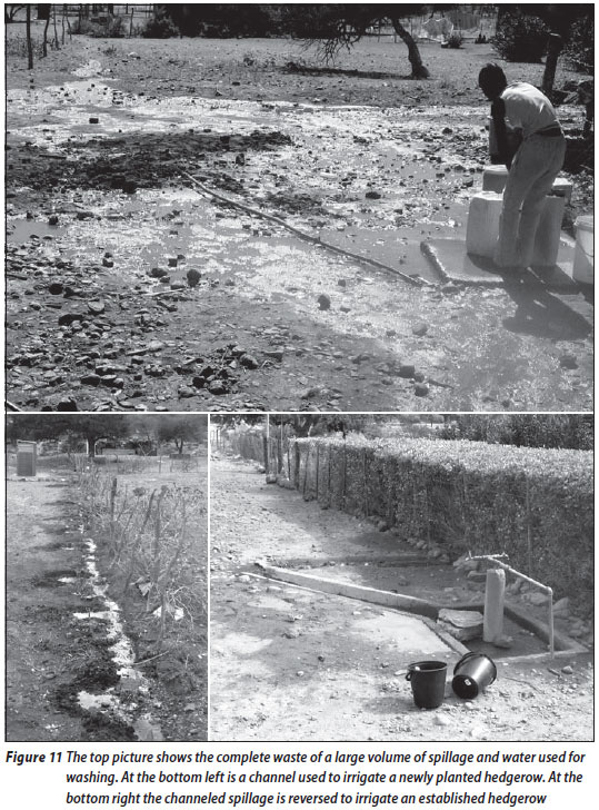
Once the spillage has been collected and diverted from the platform, it would be much more beneficial to use it productively rather than allow it to run to waste. This does not seem to be considered by designers at all, but ingenious villagers have, in isolated cases, found ways to direct the water to hedgerows, trees or even vegetable gardens. Some examples are shown in Figure 11. There can be no fixed guideline for this opportunity, other than to urge designers to consider the beneficial use of the spillage in some way or other.
The washing of laundry
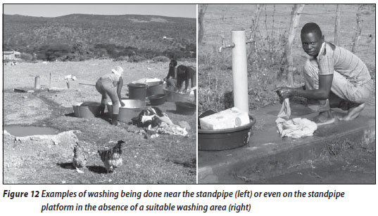
There are different preferences as to where washing should be done. In some villages, doing the laundry near the taps is discouraged, either because it impedes access to the standpipes for the higher priority containers, or to prevent the muddying of the surrounding area by letting the wash and rinse water run to waste. However, because of the inescapable logic that it requires much less toil to carry dry and semi-wet laundry to the tap and back, rather than carrying the water to the home, it is to be expected that some laundry will inevitably be washed in the immediate vicinity of the standpipes. Observation has shown that washers, mostly women, tend to prefer a grassed area, even if it is as far as 50 m away from the standpipe, as shown in Figure 12. Washing is hung on fences or bushes for a while to drip in order to reduce its mass before it is carried home. With only a standpipe available, the water for washing has to be collected with buckets or containers from the standpipe, but it seems sensible to try and incorporate some features into future standpipes to ease the burden of the washerwomen.
SOME THOUGHTS ON THE IMPROVED DESIGN OF PUBLIC STANDPIPES
The perfect public standpipe has to satisfy the following criteria:
The above considerations suggest a rectangular standpipe platform with each side of the rectangle being reserved for a specific purpose. The most important side is the side reserved for the drainage of the platform, which must be built such that the consumers cannot approach the standpipe from that direction. The other three sides must be designed according to different criteria to allow access to each of the three types of user - a high platform for the containers that are to be carried on the head, an intermediate platform for the containers that are to be loaded onto wheelbarrows after filling, and a low platform for the containers that are to be carried off the platform alongside the body.
COST CONSIDERATIONS
Would more elaborate standpipe design, along the lines suggested in this paper, not send the cost of new systems through the roof? This is a logical concern when water-supply authorities are doing their best to serve the maximum number of people within financial constraints. A comprehensive study conducted by the South African Department of Water Affairs and Forestry (DWAF 2003) showed that the water reticulation part (which includes the reticulation pipework and the standpipes) represents between 10% (for "small" systems serving 1 000 to 5 000 people) and 20% (for "very small" systems serving fewer than 1 000 people) of the capital cost of the total water system. Based on the actual reticulation pipe lengths and the number of standpipes in the villages that formed part of this survey, our own cost estimates indicate that the cost of the standpipes alone was never more than 5% of the total reticulation cost. Using these numbers in tandem, the capital cost of the standpipes therefore constitutes between 0,5% and 1,0% of the total water system cost. The relative cost of the standpipes is thus negligible and it can, and should, be a priority to pay much more care and attention to standpipe design without adding significantly to the cost burden of rural water supply.
ACKNOWLEDGMENTS
This paper reflects a survey done of the water systems in 21 villages in the Nwanedi basin in the northern part of the Vhembe District Municipality. This survey could only be done with the active support and inputs of Prof Paul Jagals and his graduate students, Mike Mokoena and Lucky Madzivandhila from the Faculty of Health Sciences at the University of Johannesburg. Gerdien Sterk from the Delft University of Technology spent a week doing preliminary fieldwork in 2006, which started the discussions on improved public standpipe design. One of the design groups of the civil engineering class of 2007 at the University of Johannesburg (Loudene Roelofz, Peter Crous, Funeka Grootboom, Buzi Mzolo and Jay Engelbrecht) provided an early conceptual prototype. Valuable comments were received from a wide range of friendly officials - Stephen Musetsho from the Department of Water Affairs (Limpopo Province), Phineas Ramovha from the Vhembe District Municipality, Chief Ne-Folovhodwe and David Tanyane, the very capable handyman and fitter taking care of the water systems at the village of Folovhodwe.
REFERENCES
Coetzee, M 2008. Standards South Africa, Pretoria, Personal communication. [ Links ]
Department of Water Affairs and Forestry 2003. Cost benchmarks: Typical unit costs for water services development projects. www.dwaf.gov.za [accessed 7 April 2008] [ Links ].
Department of Water Affairs and Forestry 2004. Technical guidelines for the development of water and sanitation infrastructure. 2nd ed. www.dwaf.gov.za [accessed 7 April 2008] [ Links ].
Jagals, P 2008. Personal communication, based on unpublished student dissertations. [ Links ]
Rietveld, L C, Haarhoff, J and Jagals, P 2008. A tool for technical assessment of rural water supply systems in South Africa. Journal of Physics and Chemistry of the Earth, 34(1-2): 43-49. [ Links ]
South African National Standard 2006. Water taps (metallic bodies). SANS 226:2004, edition 5.1. Standards South Africa, Pretoria. [ Links ]
Sterk, G 2006. Investigation into the Folovhodwe drinking water network. Unpublished internship report, Delft University of Technology, July. [ Links ]
 | JOHANNES HAARHOFF graduated as civil and environmental engineer at the University of Stellenbosch and Iowa State University. He spent the first part of his career in municipal employ, civil construction, and design and project management, before joining the University of Johannesburg in 1990, where he leads the Water Research Group. This group focuses on both applied and fundamental aspects of drinking water treatment and supply. |
 | LUUK RIETVELD studied civil engineering at Delft University of Technology with a special focus on water management. Initially, he worked for the Dutch Directorate General for International Co-operation in Mozambique as lecturer/researcher in sanitary engineering at the Eduardo Mondlane University, Maputo. He later joined Delft University of Technology and is at present Asssociate Professor in the department dealing with drinking water treatment where he supervises several PhD students specialising in this topic and related areas. He received his PhD in 2005 with a thesis entitled Improving operation of drinking water treatment through modelling. This subject is still the main focus of his research. |
 Contact details:
Johannes Haarhoff
University of Johannesburg, Department of Civil Engineering Science
PO Box 524
Auckland Park, 2006
jhaarhoff@uj.ac.za
Contact details:
Luuk Rietveld
Delft University of Technology, Department of Water Management
PO Box 5048
2600 GA Delft The Netherlands
L.C.Rietveld@tudelft.nl

