


Services on Demand
Article
 English (pdf)
 Article in xml format
 Article references
Indicators

Related links
-
 Cited by Google
 -
 Similars in Google
Share

 Permalink
South African Journal of Chemistry
On-line version ISSN 1996-840X
Print version ISSN 0379-4350
S.Afr.j.chem. (Online) vol.69 Durban 2016
http://dx.doi.org/10.17159/0379-4350/2016/v69a3
RESEARCH ARTICLE
The Synthesis of Carbon Nanomaterials using Chlorinated Hydrocarbons over a Fe-Co/CaCO3 Catalyst
Winny K. MaboyaI, II; Neil J. CovilleII; Sabelo D. MhlangaII, III, *
IDepartment of Chemistry, Faculty of Applied and Computer Sciences, Vaal University of Technology, Private Bag X021, Vanderbijlpark, 1900, South Africa
IIDST-NRF Centre of Excellence in Strong Materials and Molecular Sciences Institute, School of Chemistry, University of the Witwatersrand, Johannesburg, WITS, 2050, South Africa
IIINanotechnology and Water Sustainability Research Unit, College of Science, Engineering and Technology, University of South Africa, Florida Science Campus, Johannesburg, 1709, South Africa
ABSTRACT
The effect of chlorine on the morphology of carbon nanotubes (CNTs) prepared from a Fe-Co/CaCO3 catalyst was investigated using chlorobenzene (CB), dichlorobenzene (DCB), trichlorobenzene (TCB), dichloroethane (DCE), trichloroethane (TCE) and tetrachloroethane (TTCE) as chlorine sources using a catalytic chemical vapour deposition (CCVD) method. Toluene was used as a chlorine-free carbon source for comparison. Multi-walled carbon nanotubes (MWCNTs) were successfully synthesized. The physicochemical properties of the CNTs were studied using transmission electron microscopy (TEM), Raman spectroscopy, thermal gravimetric analysis (TGA), energy-dispersive X-ray spectroscopy (EDS), powder X-ray diffraction (PXRD) spectroscopy, and X-ray photoelectron spectroscopy (XPS) techniques. The inner and outer diameters of the MWCNTs increased with an increase in the number of chlorine atoms contained in the reactant. Chlorine incorporation into the MWCNTs was observed by EDS analysis for all reactants. Formation of'bamboo-like' structures for the MWCNTs generated from TCE and TTCE was also observed, facilitated by the presence of the high percentage of chlorine in these reactants. Numerous MWCNTs revealed the presence of small carbon nanostructures that grew on top of the dominant CNTs, suggesting an unexpected secondary carbon growth mechanism.
Keywords: Multi-walled carbon nanotubes, CVD, synthesis, chlorine, benzenes, ethanes.
1. Introduction
Nanotechnology is a topic that is attracting the interest of scientists in academia, research institutions and industry as well as government officials and journalists. Carbon nanotubes (CNTs) and carbon nanomaterials (CNMs) in general are key components in the progress of nanotechnology. Polyhedral carbon clusters (fullerenes) were discovered in 19851 and this eventually led to the seminal studies on carbon nanotubes (CNTs) by Ijima in 1991.2 CNTs offer opportunities for the development of novel material systems because they possess unique electronic properties,3 exhibit thermal conductivity that is higher than that of diamond,3 and possess mechanical properties such as stiffness, strength and resilience, which exceed those of any currently used materials.4 These unique properties render CNTs suitable for application in various fields for example, their use as supports in catalysis, nanoconveyors, field emission sources, chemical sensors, nanoelectronic devices and in fuel cells.5,6 Methods for making CNTs such as arc discharge, laser ablation, pyrolysis and catalytic chemical vapour deposition (CCVD) have been developed.7-10 To date the production of CNTs by the CCVD method remains the preferred route for their large scale production.
A limitation related to the use of CNTs in many applications has always been the difficulty in dispersing them in solvents. Scientists have thus functionalized the outer walls of CNTs with various groups like halogens and carboxylic groups to improve their solubility. Modification of CNTs has thus led to the creation of new functional and construction materials.11 Doping of the carbonaceous materials with non-carbon atoms, such as nitro-gen,12-19 boron,20-24 sulphur,25-29 oxygen30-36 and halogens11,37-55 has been explored over the past two decades. Modification of the carbon surface and electronic properties has also been explored but the effect of chlorine (Cl) on the morphology of carbon nanomaterials is not well established.
It has been shown that incorporation of Cl in the CNMs results in surface functionalization,41-44 ease of purification,40,43,45,46 increased yields47-49 and surface restructuring.49,50 The presence of chlorine atoms thus produces materials with increased inner diameters, which results in filling of CNTs with metal particles51-53 and provides a chemically modified pathway to an ordered carbon product.48,49,54 Liquid chlorination of multi-walled CNTs (MWCNTs) gave a Cl loading of about 0.23 at.%40 based on EDS. XPS analysis of single-walled carbon nanotubes produced from dichlorocarbene gave Cl substituted CNTs at a concentration of 1.6 at.%.41 A small number of Cl anions were also observed on the surface of the CNTs generated from dichloromethane by XPS analysis.11 Chlorine-functionalized CNTs were also produced in the gas phase using a ball-milling method.42 Purification of CNTs with Cl in both the liquid phase (using CCl4) and the gas phase to remove metal particles showed that the gas phase was more effective, but a high concentration of Cl on the surface was loaded in the liquid phase.43 Purification and growth of vertically aligned MWCNTs in the presence of Cl was also reported, which resulted in the synthesis of CNT arrays with 3.5 mm height.44
The yield of MWCNTs increased from 10 % to over 50 % using an arc discharge method and KCl as a promoter.47 CNMs produced from chlorobenzene were more ordered and their yield increased as compared to those obtained from benzene.48 The beneficial role of halogens involving charge transfer with Ni particles has been shown by other authors.48,49 An interaction between Cl and Ni leading to metal site restructuring was observed when carbon nanofibres (CNFs) were grown from Ni/SiO2 and chlorobenzene.50 When the CNMs were grown over Ni/SiO2 carbon yields were also shown to increase in the presence of Cl, in the order C2H6 <C2H4 <C2H4Cl2 <C2H3Cl3 < C2H2Cl2 £ C2HCl3. The fibre diameter increased with increased Cl substitution in the feed.49 Structural changes to give carbons with different structure (CNFs to carbon spheres) were observed when CCl2=CHCl was used as a chlorine feed.49 CNFs with tripod-like morphology were also synthesized over a NiO xerogel catalyst using trichloroethylene as Cl feed and carbon source.54 Synthesis of CNTs over a Fe-Ni catalyst was achieved using chlorinated benzenes and it was observed that the hollow degree of the CNTs increased with an increase in Cl content in the feed, which resulted in the CNTs being filled with a Fe-Ni alloy.51 Previous work in our group has also shown that the use of chloro-benzene can facilitate growth of CNTs with a large inner cavity.53 The participation of Cl was found to play an important role in the synthesis of turbostratic CNFs by pyrolysis of a 1,2-dichloro-ethane/ethanol mixture in the presence of a nickel catalyst.55 Ni-Cl bonding on the surface of the catalyst created a poor crystalline layer, leading to a coarse surface which caused the disordered precipitation of carbon species and thus the formation of turbostratic CNFs.55 Most of the studies of the role of chlorine on the morphology of the CNMs have been investigated using a nickel or iron-nickel catalyst.
In previous studies by our group it was found that a Fe-Co/CaCO3 catalyst can be used to make good quality CNTs56,57 and nitrogen doped CNTs.58 To further explore the role of this catalyst we have investigated the role of chlorine on the morphology of CNTs produced by pyrolysis of various chlorine-substituted benzene and ethane feeds using a CCVD method. The results of the study are shown below.
2. Experimental
Fe(NO3)3-9H2O (SigmaAldrich) >98 %,Co(NO3)2-6H2O (Sigma Aldrich) >98 %, CaCO3 (Sigma Aldrich) > 99 %, HNO3 (Sigma Aldrich) > 98 % ACS, chlorobenzene (CB) (Merck), >99 % GC, 1,2-dichlorobenzene (DCB) (Sigma Aldrich) 99 % Reagent plus, 1,2,4-trichlorobenzene (TCB) (Sigma Aldrich) 99 % GC, 1,2-dichloroethane (DCE) (BDH reagent) AnalaR grade, 1,1,2-trichloroethane (TCE) (Fluka Chemika) >98 % GC, 1,1,2,2-tetrachloroethane (TTCE) (UniLAB SAARChem) 98 % GLC and toluene (UniLab SAARChem, Merck) ACS reagent grade, were used. All the reagents were commercially available and used without further purification.
2.1. Preparation of Catalyst by the Wet Impregnation Method
The preparation of catalysts was done as reported in previous studies.56,57Fe(NO3)3-9H2O and Co(NO3)2-6H2O were used to prepare the catalyst. Calculated amounts of the Fe and Co nitrates were mixed, ground to a fine powder and dissolved in distilled water to make a 0.3 mol L-1 Fe-Co (50:50 m/m) precursor solution. This solution (30 mL) was added to the CaCO3 support (20 g) and the mixture was stirred for 30 min. The metal-support mixture was then dried in the oven at 120 °C for 12 h, cooled to room temperature, ground and finally screened through a 150 μm sieve. The catalyst powder was then calcined at 400 °C for 16 h in a static air oven. This catalyst was completely characterized as reported in our previous article.56
2.2. Carbon Nanotube Synthesis
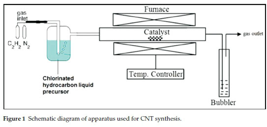
The catalyst (1.0 g) was spread in a quartz boat and the boat was placed in the centre of the quartz tube. The furnace was then heated to 700 °C at a rate of 10 °C min1 under flowing N2 (50 mL min 1). Once the temperature reached 700 °C, the N2 flow rate was set to 240 mL min-1 and C2H2 was set at 90 mL min1 for chlorinated benzenes; for chlorinated ethanes flow rates were set at 280 mL min1 N2 and 50 mL min1 C2H2, respectively. Both gases were bubbled through a chlorinated organic solvent, before introduction into the quartz tube. After 60 min of reaction time, the C2H2 flow and bubbling was stopped and the system was left to cool down to room temperature under a continuous flow of N2 (50 mL min-1). The reaction setup is shown in Fig. 1. The quartz boat was then removed from the reactor and the carbon deposit (Cl-MWCNTs) that formed was weighed.
2.3. Purification of the CNTs
Purification of the CNT materials was performed as described elsewhere.56 The CNTs were purified by stirring the products in 30 % HNO3 for at least 30 min at room temperature. The acid-treated CNTs were then washed with distilled water until the washings were neutral and dried in an oven at 120 °C for 12 h.
2.4. Characterization of the Catalyst and CNTs
The morphology and size distribution of the CNTs before and after HNO3 treatment were analyzed by transmission electron microscopy (TEM) using a FEI TECNAI G2 SPIRIT. The samples for TEM analysis were prepared by sonication in ethanol and thereafter deposited on a holey carbon-coated TEM Cu grid. The percentage yield of the carbon deposit (% C) was determined as described elsewhere.59 The CNTs were also characterized by Raman spectroscopy using a Jobin-Yvon T6400 micro-Raman spectrometer. Excitation was provided by the 532 nm green laser with spectral resolution of 3-5 cm-1. The impurity content of the CNTs was monitored by thermogravimetric analysis (TGA) using a Perkin Elmer TGA 7. The sample was loaded onto a platinum pan and heated to 900 °C at a heating rate of 5 °C min1, in a flowing air and nitrogen stream both at 20 mL min 1. The phase composition of the samples was determined by powder X-ray diffraction (PXRD) using a D2 Bruker PXRD with a continuous scan mode using CoKa radiation. The scan range was 10-90 2 θ degree. The presence of chlorine species in the CNT samples was determined by energy dispersive X-ray spectros-copy (EDS) incorporated into the SEM. XPS analysis was performed using a PHI 5000 Versaprobe - Scanning ESCA Microprobe operating with a 100 μm 25 W 15 kV Al monochromatic X-ray beam. The samples were sputtered with a 2 kV 2 1x1 mm raster - Ar ion gun at a sputter rate of about 18 nm min-1 for 60 seconds.
3. Results and Discussion
The results from the studies of Mhlanga et. al.56and Tetana et. al.58 showed that good quality MWCNTs and nitrogen doped MWCNTs can be produced from a Fe-Co/CaCO3 catalyst. This led us to assume that other hydrocarbons, such as chlorinated hydrocarbons, could be used to make CNTs over this catalyst. All the products made in the study were black in colour; those obtained with CB, DCB, DCE, and TCE as chlorine sources appeared spongy, while those obtained with TCB, TTCE and toluene were powdery.
3.1. Structural Analysis of the Cl-MWCNTs
TEM analysis of the carbon deposits after acid treatment showed that the morphologies of CNMs varied with the type of feed used. A range of carbons were produced in varying amounts, i.e. amorphous material, CNFs and CNTs (open and bamboo), but CNTs were the predominant products formed in most cases.
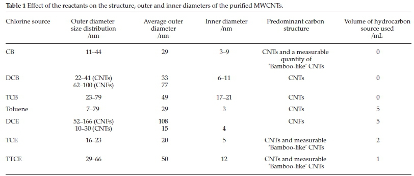
Purified CNTs produced from CB, DCB and TCB all appeared entangled with a wavy (cooked spaghetti-like) morphology (Figs. 2, 3 and 4). It appears that all the aromatic chlorine containing reactants gave similar carbon yields (ca. 63-70 %). Purified MWCNTs produced using TCB were more entangled and their inner and outer diameters appeared uniform over the entire length of the tube (Fig. 4). The diameters of the purified CNTs produced from the three reactants are given in Table 1. Both the inner and outer diameters increased with the reactant's chlorine content.
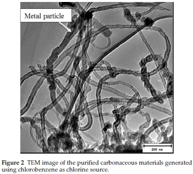
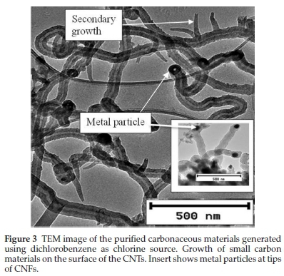

TEM analysis also showed the presence of rod shaped catalyst particles embeddeinside the nanotubes (Figs. 2 and 4) and some at the tips of the CNFs (Fig. 3 insert), which were formed as a result of un-reacted catalyst particles. This shows that CNTs obtained from the aromatic compounds contained some metal particles which were difficult to purify and this was attributed to the coiled structures as well as their narrow inner diameters (Table 1).
Further analysis of TEM images of purified carbon materials produced from DCB revealed the presence of small open ended fibrous particles attached to the outside of the CNTs (Fig. 3 and Supplementary Fig. S1). The secondary nanofibres were initially broad and then became narrower as they grew from the primary CNTs. Close inspection of the numerous CNFs produced revealed that they all have an inverted cap-like morphology suggesting a loss of metal catalyst particles at the tip. The secondary growth was thought to originate from unreacted catalyst particles that were left on the surface of the CNTs grown via a tip-growth mechanism. The catalyst responsible for the secondary growth was presumably trapped on the surface of the growing CNTs and provided a growth site for secondary CNTs. Similar behaviour was reported in the literature where some particles were found attached to the ends of CNTs.60
A small carbon deposit was obtained when TCB was used as chlorine source (Fig. 4). The large amount of chlorine in the TCB feed was responsible for the few CNTs measured, which was attributed to Cl/Fe-Co interactions leading to metal site restructuring that impacted on carbon diffusion/precipitation.50 The various morphologies that resulted from the different chlorinated feeds were possibly associated with the interaction of chlorine with the catalyst particles. As more chlorine was introduced into the reactor the rate of CNT formation decreased, due to catalyst poisoning.
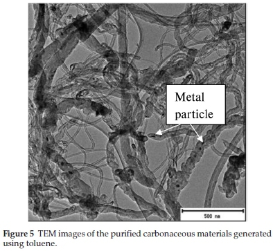
Toluene as a representative of a Cl free aromatic hydrocarbon was also tested in this study (Fig. 5). Toluene produced irregular CNTs of similar inner (3 nm) and variable outer diameters (7-79 nm). MWCNTs of variable inner (7-14 nm) and outer (22-64 nm) diameters were produced from a mixture of toluene and ferrocene; iron oxide particles were also seen embedded inside some on the outer walls of the CNTs.61 In another study mixed quality carbon structures (irregular tubes of different diameters, rods, spirals, fibres, etc.) were found by electron microscopy when toluene was used as a hydrocarbon source over an Fe/silica substrate.62 Metal particles can also be seen embedded inside some of the CNTs produced in this study (Fig. 5). Comparison of the CNTs produced using chlorinated benzenes with those obtained using toluene shows that the presence of chlorine in the aromatic feed leads to more regular CNTs.
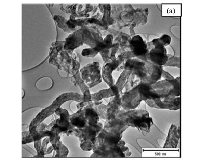
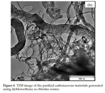
TEM images of the purified MWCNTs produced from the three chlorinated ethanes all appeared entangled with a coiled spaghetti-like shape (Figs. 6, 7 and 8). The purified CNMs produced from DCE contained a mixture of mainly CNFs (Fig. 6a) and some CNTs (Fig. 6b). CNTs with little by-product formation were obtained from TCE and TTCE (Figs. 7 and 8). The formation of CNFs must relate to the amount of hydrogen present in the DCE (C2H4Cl2) feed.63
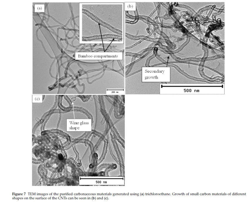
The carbon yields obtained using chlorinated ethanes were 92, 82 and 81 % for DCE, TCE and TTCE, respectively. The carbon yields were not dependant on the amount of chlorine present in the feed. The TEM images of carbon materials produced from TCE are shown in Fig. 7. The three figures reveal different features associated with the CNTs. Fig. 7a highlights the entangled CNTs and many of these CNTs appear to show bamboo compartment features. Fig. 7b shows secondary growth of short CNTs with hollow tips, which seem to originate from the main CNTs. These are similar to those seen above in Fig. 3 when DCB was used as a reactant, but here tubes do not taper and the hollow structures can be clearly seen. Finally wine glass-like secondary structures were also seen in Fig. 7c. These secondary structures had very thin walls and did not show the presence of catalyst particles. The presence of un-reacted catalyst material on the surface of the CNTs could be responsible for the secondary growth via a tip-growth mechanism.
MWCNTs produced using TTCE also appeared entangled with different outer wall diameters (Fig. 8a, b). Numerous small particles can also be observed on the surface of the CNTs, but no secondary fibre growth was observed. This might also be attributed to the amount of chlorine in the feed, which if present in large amounts inhibits the growth of secondary fibrous particles. The inner diameters of the MWCNTs produced using chlorinated ethanes also increased with an increase in the amount of Cl contained in the organic reagent (Table 1), which suggests HCl-induced metal agglomeration, as has been demonstrated elsewhere.48,50
TEM images of carbon materials produced from TCE and TTCE (Figs. 7a and 8b, respectively) also revealed some morphological differences. The carbon materials showed nanotubes with 'segmented' appearance, i.e. a 'bamboo-like' structure. TEM images have been reported previously in the literature where 'bamboo-like' nanofibres were produced when DCE, dichloroethylene and TCE were used as sources of Cl over Ni/SiO2 catalyst and were attributed to a seed metal reconstruction leading to unequal diffusion of carbon through the metal particle.49 In our case the bamboo structures might arise from effects related to the interaction of chlorine with metal particles leading to catalyst restructuring. Bamboo structures were not seen for the CNTs obtained in this study when DCE was used which might be due to their limited production but the segmentation was observed from CNFs produced from DCE (Supplementary Fig. S2). More segmented CNTs were observed for CNTs produced from TCE (Fig. 7a). The distances between compartments appeared similar for both reactants.
3.2. TGA and PXRD Analysis
TGA and derivative TGA (DTGA) curves of the purified (Fig. 9) and un-purified (Supplementary Fig. S3) MWCNTs samples were recorded in an oxygen atmosphere to monitor the weight loss and thermal stability of the samples. CNTs synthesized in the presence of chlorine using CB, DCB and TCB as chlorine sources, revealed oxidation peaks at ~612 °C, 601 °C and 589 °C, respectively (Table 2). Previously, Mhlanga et. al.56showed that CNTs synthesized using this catalyst with non-chlorinated reactants oxidized at ~550 °C.
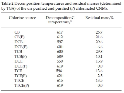
From the thermographs and DTGA data (Table 2) it can be seen that the decomposition temperature of the purified CNTs made from the aromatic carbon feeds decreased with an increase in the amount of chlorine. The DTGA curves of these CNTs also show the appearance of peaks at ~690 °C. These peaks are well-defined when generated from CB, but appeared as shoulder peaks for DCB and TCB. These peaks are assigned to the presence of small amounts of graphitic materials.64,65
Further evaluation of the thermographs obtained from chlorinated benzenes, revealed that the CNTs contained residues even after purification in 30 % HNO3 for 30 min (~21 %, 6 % and 10 % for CB, DCB and TCB (Table 2)). An attempt was made to further purify the materials generated from CB by stirring the product in 30 % HNO3 for 2 h and 3 h (Supplementary Fig. S4). The residual mass had not changed (~18 % and 20 %) after the 2 h and 3 h acid treatments. A further harsher treatment was employed by refluxing the product in acid at 110 °C for 4 h which resulted in destruction of the CNTs structure but a residual non-carbon mass of 8 % still remained (Supplementary Fig. S4). This showed that catalyst particles remained intact and could not be removed from the CNTs despite the harsh acid treatment used. The results correlated with the TEM observations; where images showed the presence of many catalyst particles embedded inside the CNTs (Fig. 2) as well as at the tip of a few CNFs made from materials produced using DCB (insert in Fig. 3a). This implied that the catalyst particles were embedded (i) inside bamboo structures, (ii) within the graphitic layers of the CNTs and (iii) inside the tips of some CNFs (insert in Fig. 3). Similar results were observed in the literature using a FeNi catalyst when residual metal contents of 31, 27 and 24 wt.% were observed from TGA curves generated from trichlorobenzene, dichlorobenzene and chlorobenzene as carbon sources; a 3 wt.% residue was observed under the same conditions using xylene as carbon precursor.51
TGA (Fig. 9c) and DTGA (Fig. 9d) curves generated from chlorinated ethanes all show similar oxidation peaks at ~619 °C (for DCE and TTCE) and ~621 °C for TCE. The chlorinated materials are more thermally stable than those produced from chlorinated benzenes. Catalyst particles were not embedded inside the CNTs (<2 %) for the CNTs produced from the chlorinated ethanes.
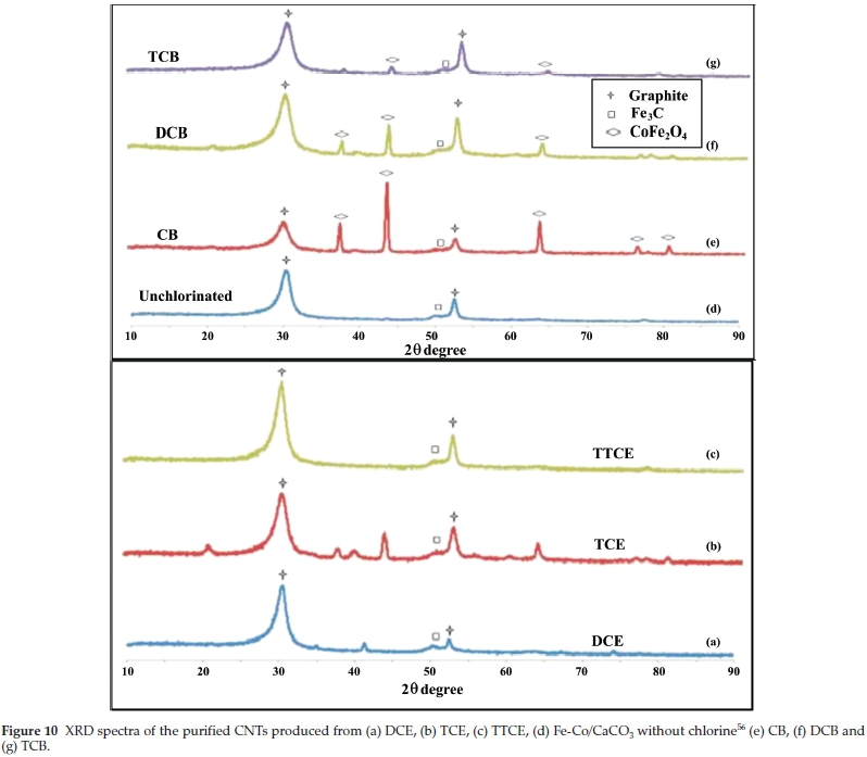
XRD characterization was performed, to further analyze the purity of the CNTs. The XRD profiles of the acid-treated (purified) MWCNTs generated from chlorinated hydrocarbons are presented in Fig. 10. All XRD patterns show the presence of graphitic carbon represented by a C(002) peak at 2 θ = 30°and another peak at 2 θ = 53 °. The peak at 2 θ = 30 ° has been attributed to MWCNTs.66 The C(002) peak for CNTs synthesized without chlorine was broader when compared to C(002) peaks of CNTs synthesized in the presence of chlorine. The full width at half maximum (FWHM) of the C(002) peak decreased after introduction of chlorine, and increased with an increase in the amount of chlorine in the feed (Table 3). The smaller broadening of the FWHM of the C(002) peak with an increase in the amount of chlorine was attributed to an increased crystallinity of the materials.66,67
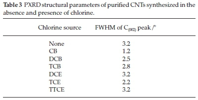
For chlorinated ethanes, the FWHM of the C(002) peak decreased in the order DCE=TTCE>TCE (Table 3). CNTs synthesized using TCE were more crystalline than those generated from DCE and TTCE. These observations agree well with the TGA graphs where CNTs generated from TCE were oxidized at higher temperatures, meaning they were more thermally stable than those generated from other chlorinated ethane feeds.
Another broad peak closer to the one at 53 ° was attributed to small amounts of carbides in the carbon material. PXRD analysis revealed peaks at 2 θ ~38 °, 43 ° and 64 ° due to the presence of cobalt ferrite nanoparticles68 for CNTs generated from CB, DCB, TCB and TCE, confirming that some metal particles still remained after purification as confirmed by the TGA analysis. Other diffraction peaks can be seen in the XRD patterns generated from TCE after purification which can be due to the presence of catalyst residues remaining after purification.
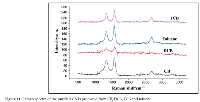
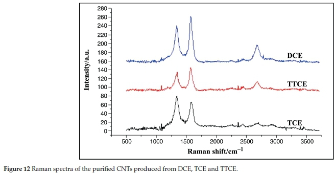
3.3. Raman Spectral Analysis
The crystalline nature of the MWCNT structures was verified by Raman spectroscopy. Raman spectra for all chlorinated MWCNTs (Figs. 11 and 12) shows a D-band at around 1350 cm-1 which is attributed to defects in the curved graphene layers and tube ends and a G-band at around 1576 cm-1 which correspond to the movement in the opposite direction of two neighbouring carbon atoms in a graphene sheet. The intensity ratio ID/IG is known to depend on the structural characteristics of the CNTs.69 An increase in ID/IG corresponds to a higher proportion of sp3 carbon that is usually attributed to the presence of more structural defects.70ID/IG ratios of 0.96,0.96 and 0.76 were observed for CNTs produced from CB, DCB and TCE, respectively (Table 4). These ratios increased slightly as compared to those shown by Mhlanga et.al.56for unchlorinated CNTs (0.7). This shows that the CNTs remained graphitic after addition of chlorine, which agrees with the TGA and XRD data. The ID/IG peak ratio of the CNTs generated from TCB is also comparable (~0.76) with the ratio obtained for CNTs produced without chlorine (~0.756).
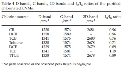
The ID/IG peak ratio for CNTs produced from DCE (0.89) and TTCE (0.89) were similar, and agreed well with the TGA and the XRD data. Structural defects, shown by the highly intense D peak (Fig. 12), were obtained when TCE was used as a source of chlorine. These can be associated with the formation of bamboo-like CNTs and the growth of open-ended carbon nanostructures onto the main CNTs as observed from TEM images. An overtone 2D peak was also observed at ~2680 cm-1in the spectra of CNTs generated from DCE, TTCE, CB, TCB and toluene (Figs. 11 and 12). This suggests that the materials have a good percentage of graphitic carbon, which agrees with the lower ID/IG ratios produced for these materials.
3.4. Energy Dispersive X-ray Spectroscopy Analysis of the Purified Chlorinated CNMs
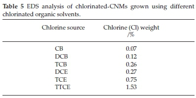
The EDS analysis (Table 5) revealed the presence of Cl species in all chlorinated samples. It was found that the amount of Cl on the MWCNTs (i) increased with an increase in the amount of Cl in the organic reagents and (ii) aromatic reactants gave less Cl substitution than aliphatic reactants (Table 5). This demonstrates that the use of highly chlorine substituted feeds, gives greater functionalization of CNTs with Cl. The data correlate with the TEM data where TCE and TTCE gave more segmented CNTs; hence incorporation of Cl into the carbon structure and secondary fibrous growth observed on the surface of the CNTs can be related to the amount of Cl present.
3.5. XPS Analysis
The surface characteristics of purified MWCNTs were analyzed by XPS. Supplementary Figs. S5 and S6 shows the deconvoluted XPS plots of C1s and Cl2p for all the studied chlorinated organics. The C1s curve for all MWCNTs was deconvoluted into five components with binding energies of ~284.0, 284.8, 285.4, 286.1 and 286.8 eV (Table 6). Four of these peaks are readily assigned to C sp2,Csp3, C-OH and C=O; it is possible to tentatively assign the fifth peak at 285.4 to C covalently attached to Cl 72,73

The Cl 2p spectrum of CNTs generated from chlorinated organics (Supplementary Figs. S5 and S6) showed two signals at ~201 and 199 eV which are assigned to the 2p1/2 and 2p3/2 of a chloride ion (e.g. as found in metal chlorides).73,74 Unfortunately the 2p1/2 peak associated with covalent C-Cl bonds overlaps with the 2p3/2 associated with the presence of the chloride ion peak. Furthermore, the low concentration of the Cl in the samples generates very small peaks for Cl and this makes it difficult to quantify the amount of covalent Cl in the CNTs. However the 2p1/2/2p3/2 ratios for the Cl peaks indicate values below ca. 1.6, the value expected when only ionic chloride is present (Supplementary Table S1). This suggests that indeed small amounts of C-Cl bonds have been made; the CNTs made from TTCE thus have the largest amount of C-Cl bonds. This chlorine would be attached to sp2 carbons at the periphery of the aromatic structures, or at defect sites.72 The low Cl content is not unexpected as C-Cl bonds are readily broken under the high temperature condition employed in the CNT synthesis.
4. Conclusion
The role of chlorine on the morphology of MWCNTs synthesized by the catalytic pyrolysis of chlorinated organic reagents over a Fe-Co/CaCO3 catalyst was studied. The structural morphology of CNTs produced depended on the amount of chlorine present in the feed and on the type of organic chlorine compound used. CNTs generated from TCE and TTCE showed the formation of bamboo-like structures, which were related to catalyst restructuring by chlorine. Secondary nanofibre and nanotube growth onto the main CNTs was observed when TCE and DCB chlorine sources were used. Carbon nanofibres were found to be dominant when chlorine sources that contained high concentration of hydrogen were used. Addition of chlorine favoured the growth of carbon materials of high purity. Alkanes gave cleaner CNTs with higher carbon yields than those formed from the aromatic reactants. XPS studies revealed that most of the Cl found in the CNTs was ionic chlorine, most probably associated with the Fe and in the CNT tubes. Some surface functionalization of carbon with chlorine is suggested when TTCE was used as reagent. The role of chlorine on the morphology of nitrogen-doped CNTs and the use of chlorinated MWCNTs as adsorbents for selected heavy metals in wastewater treatment is under way.
Acknowledgements
The authors would like to acknowledge financial support from Vaal University of Technology and the University of the Witwatersrand. We also thank the MMU unit at University of the Witwatersrand for use of the microscopes.
References
1 H.W. Kroto, J.R. Heath, S.C. O'Brien, R.F. Curl and R.E. Smalley, C60: Buckminsterfullerene, Nature, 1985, 318, 162-163. [ Links ]
2 S. Ijima, Helical Microtubules of graphitic carbon, Nature, 1991, 354, 56-66. [ Links ]
3 P.G. Collins and P. Avouris, Nanotubes for electronics, Scientific American, 2000, 283, 62-69. [ Links ]
4 Q. Zeng, Z. Li and Y. Zhou, Synthesis and application of carbon nanotubes, J. Nat. Gas Chem, 2006,15, 235-246. [ Links ]
5 B.M. Endo, T. Hayashi, Y.A. Kim and M. Terrones, M.S. Dresselhaus, Applications of carbon nanotubes in the twenty-first century, Phil. Trans. Roy. Soc. London. A., 2004, 362, 2223-2238. [ Links ]
6 M. Terrones, A. Jorio, M. Endo, Y.A. Kim, T. Hayashi, H. Terrones, J.-C. Charlier, G. Dresselhaus and M.S. Dresselhaus, New direction in nanotube science, Mater. Today, 2004, 7, 30-5. [ Links ]
7 H. Zeng, L. Zhu, G. Hao and R. Sheng, Synthesis of various forms of carbon nanotubes by AC arc discharge, Carbon, 1998, 36, 259-262. [ Links ]
8 A. Thess, R. Lee, P. Nikolaev, H. Dai, P. Petit, J. Robert, C. Xu, Y.H. Lee, S.G. Kim, A.G. Rinzler, D.T. Colbert, G.E. Scuseria, D. Tombnek and J.E. Fischer, Crystalline ropes of metallic carbon nanotubes, Science, 1996, 273, 483-87. [ Links ]
9 D.C. Li, L. Dai, S. Huang, A.W.H. Mau and Z.L. Wang, Structure and growth of aligned carbon nanotube films by pyrolysis, Chem. Phys. Lett, 2000, 316, 349-355. [ Links ]
10 V. Ivanov, J.B. Nagy, P. Lambin, A. Lucas, X.B. Zhang, X.F. Zhang, D. Bernaerts, G. Van Tendeloo, S. Amelinckx and J. Van Landuyt, The study of carbon nanotubules produced by catalytic method, Chem. Phys. Lett., 1994, 223, 329-335. [ Links ]
11 S.Y. Brichka, G.P. Prikhod'ko, Y.I. Sementsov, A.V. Brichka, G.I. Dovbeshko and O.P. Paschuk, Synthesis of carbon nanotubes from a chlorine-containing precursor and their properties, Carbon, 2004, 42, 2581-2587. [ Links ]
12 K. Chizari, A. Vena, L. Laurentius and U. Sundararaj, The effect of temperature on the morphology and chemical surface properties of nitrogen-doped carbon nanotubes, Carbon, 2014, 68, 369-379. [ Links ]
13 C. Wang, Z. Huang, L. Zhan, Y. Wang, W Qiao, X. Liang and L. Ling, Nitrogen-doped carbon nanotubes synthesized with carbon nanotubes as catalyst, Diam. Rel. Mat., 2011, 20, 1353-1356. [ Links ]
14 T. Sharifi, F. Nitze, H.R. Barzegar, C.-W. Tai, M. Mazurkiewicz, A. Malolepszy, L. Stobinski and T. Wâgberg Nitrogen-doped multi- walled carbon nanotubes produced by CVD-correlating XPS and Raman spectroscopy for the study of nitrogen inclusion, Carbon, 2012, 50, 3535-3541. [ Links ]
15 G. Bepete, Z.N. Tetana, S. Lindner, M.H. Rummeli, Z. Chiguvare and N.J. Coville, The use of aliphatic alcohol chain length to control the nitrogen type and content in nitrogen doped carbon nanotubes, Carbon, 2013, 52, 316-325. [ Links ]
16 H. Liu, Y. Zhang, R. Li, X. Sun and H. Abou-Rachid, Thermal and chemical durability of nitrogen-doped carbon nanotubes, J. Nanopart. Res., 2012,14, 1016-1023. [ Links ]
17 L. Faba, Y.A. Criado, E. Gallegos-Suáres, M. Pérez-cadenas, E. Diaz, I. Rodriquez-Ramos, A. Guerrero-Ruiz and S. Ordonez, Preparation of nitrogen-containing carbon nanotubes and study of their performance as basic catalysts, Appl. Catal. A: Gen., 2013, 458, 155-161. [ Links ]
18 R. Czerw, M. Terrones, J.-C. Charlier, X. Blasé, B. Foley, R. Kamalakaran, N. Grobert, H. Terrones, D. Tekleab, P.M. Ajayan, W. Blau, M. Rühle and D.L. Carroll, Identification of electron donor states in N-doped carbon nanotubes, Nano. Lett., 2001, 9, 457-560. [ Links ]
19 S. Maldonado, S. Morin and K. Stevenson, Structure, composition and chemical reactivity of carbon nanotubes by selective nitrogen doping, Carbon, 2006, 44, 1429-1437. [ Links ]
20 P.L. Gai, O. Stephan, K. McGuire, A.M. Rao, M.S. Dresselhaus, G. Dresselhaus and C. Colliex, Structural systematics in boron-doped single wall carbon nanotubes, J. Mater. Chem., 2004,14, 669-675. [ Links ]
21 R. Czerw, P.-W Chiu, Y.-M. Choi, D.-S. Lee, D.L. Carroll, S. Roth and Y.-W. Park, Substitutional boron-doping of carbon nanotubes, Curr. Appl. Phys., 2002, 2, 473-77. [ Links ]
22 H.J. Ceragioli, A.C. Peterlevitz, J.C.R. Quispe, A. Larena, M.P. Pasquetto, M.A. Sampaio and V Baranauskas, Synthesis and characterization of boron-doped carbon nanotubes, J. Phys.: Conf. Ser., 2008, 100, 052029, DOI: 10.1088/1742-6596/100/5/052029. [ Links ]
23 K. McGuire, N. Gothard, P.L. Gai, M.S. Dresselhaus, G. Sumana- sekera and A.M. Rao, Synthesis and Raman characterisation of boron-doped single-walled carbon nanotubes, Carbon, 2005, 43, 219-227. [ Links ]
24 F.H. Monteiro, D.G. Larrude, M.E.H. Maia da Costa, L.A. Terrazos, R.B. Capaz and F.L. Freire Jr., Production and characterization of boron-doped single wall carbon nanotubes, J. Phys. Chem. C, 2012, 116, 3281-3285. [ Links ]
25 T. Cui, R. Lv, Z.H. Huang, F. Kang, K. Wang and D. Wu, Effect of sulphur on enhancing nitrogen-doping and magnetic properties of carbon nanotubes, Nanoscale. Res. Lett., 2011, 6, 77-82. [ Links ]
26 F. Bottger-Hiller, A. Mehner, S. Anders, L. Kroll, G. Cox, F. Simon and S. Spange, Sulphur-doped porous carbon rom a thiophene-based twin monomer, Chem. Comm., 2012, 48, 10568-10570. [ Links ]
27 C. Shan, W. Zhao, X.L. Lu, D.J. O'Brien, Y. Li, Z. Cao, A.L. Elias, R. Cruz-Silva, M. Terrone, B. Wei, and J. Suhr, Three-dimensional nitrogen-doped multiwall carbon nanotube sponges with tunable properties, Nano. Lett., 2013,13, 5514-5520. [ Links ]
28 Q. Shi, F. Peng, S. Liao, H. Wang, H. Yu, Z. Liu, B. Zhang and D. Su, Sulphur and nitrogen co-doped carbon nanotubes for enhancing electrochemical oxygen reduction activity in acidic and alkaline media, J. Mater. Chem. A., 2013,1, 14853-14857. [ Links ]
29 J. Li, L. Wang, Y.J. Su, P. Liu and Y.F. Zhang, Semiconducting single walled carbon nanotubes synthesized by S-doping, Nano-Micro Lett., 2009, 1 , 9-13. [ Links ]
30 X. Qu, P.J.J. Alvarez and Q. Li, Photochemical transformation of carboxylated multiwalled carbon nanotubes: role of reactive oxygen species, Environ. Sci. Technol, 2013,47, 14080-14088. [ Links ]
31 B. Zhong, H. Liu, X. Gu and D.S. Su, Study of the role of surface oxygen functional groups on carbon nanotubes in the selective oxidation of acrolein, Chem. Cat. Chem., 2014, 6, 1553-1557. [ Links ]
32 D. Srivastava, T. Susi, M. Borghei and L. Kari, Dissociation of oxygen on pristine and nitrogen-doped carbon nanotubes: aspin polarized density functional study, RSC Adv., 2014, 4, 15225-15235. [ Links ]
33 G.D. Nessim, A. Al-Obeidi, H. Grisaru, E.S. Polsen, C.R. Oliver, T. Zimrin, A.J. Hart, D. Aurbach and C.V. Thompson, Synthesis of tall carpets of vertically aligned carbon nanotubes by in situ generation of water vapour through preheating of added oxygen, Carbon, 2012, 50, 4002-4009. [ Links ]
34 P.C.P. Watts, N. Mureau, Z. Tang, Y. Miyajima, J.D. Carey and S.R.P. Silva, The importance of oxygen-containing defects on carbon nanotubes for the detection of polar and non-polar vapours through hydrogen bond formation, Nanotechnol., 2007, 18, 175701, DOI: 10.1088/0957-4484/18/17/175701. [ Links ]
35 J. Zhao and R.-H. Xie, Electronic and photonic properties of doped carbon nanotubes, J. Nanosci. Nanotechnol., 2003, 3, 459-478. [ Links ]
36 S. Niyogi, M.A. Hamon, H. Hu, B. Zhao, P. Bhowmik, R. Sen, M.E. Itkis and R.C. Haddon, Chemistry of single-walled carbon nano tubes, Acc. Chem. Res., 2002, 35, 1105-1113. [ Links ]
37 S.M. Kim, K.K. Kim, Y.W. Yo, M.H. Park, S.J. Chae, D.L. Duong, C.W. Yang, J. Kong and Y.H. Lee, Role of anions in the AuCl3-doping of carbon nanotubes, ACS Nano., 2011, 5, 1236-1242. [ Links ]
38 J.K. Wassei, K.C. Cha, V.C. Tung, Y. Yang and R.B. Kaner, The effects of thionyl chloride on the properties of graphene and graphene-carbon nanotube composites, J. Mater. Chem., 2011, 21, 3391-3396. [ Links ]
39 D.L. Duong, I.H. Lee, K.K. Kim, J. Kong, S.M. Lee and Y.H. Lee, Carbon nanotube doping mechanism in a salt solution and hygroscopic effect: density functional theory, ACS Nano., 2010, 4, 5430-5436. [ Links ]
40 J.-M. Yuan, X.-H. Chen, X.-H Chen, Z.-F. Fan, X.-G. Yang and Z.-H.Chen, An easy method of purifying multi-walled carbon nanotubes by chlorine oxidation, Carbon, 2008, 46, 1266-1269. [ Links ]
41 W.H. Lee, S.J. Kim, W.J. Lee, J.G. Lee, R.C. Haddon and P.J. Reucroft, X-ray photoelectron spectroscopic studies of surface modified single- walled carbon nanotubes material, Appl. Surf. Sci., 2001,181,121-127. [ Links ]
42 Z. Kónya, I. Vesselenyi, K. Niesz, A. Kukovecz, A. Demortier, A. Fonseca, J. Delhalle, Z. Mekhalif, J.B. Nagy, A.A. Koós, Z. Osvâth, A. Kocsonya, L.P. Biró and I. Kiricsi, Large scale production of short functionalized carbon nanotubes, Chem. Phys. Lett., 2002, 360, 429-435. [ Links ]
43 I. Pelech, U. Narkiewicz, D. Moszynski and R. Pelech, Simultaneous purification and functionalization of carbon nanotubes using chlori- nation, J. Mater. Res., 2012, 27, 2368-2374. [ Links ]
44 C. Ghemes, A. Ghemes, M. Okada, H. Mimura, T. Nakano and Y. Inoue, Study of growth enhancement of multiwalled carbon nanotubes by chlorine-assisted chemical vapour deposition, Japanese J. Appl. Phys., 2013, 52 , 035202. [ Links ]
45 J. Barkauskas, I. Stankevièiene and A. Selskis, A novel purification method of carbon nanotubes by high temperature treatment with tetrachloromethane, Sep. Pur. Tech., 2010, 71, 331-336. [ Links ]
46 J.L. Zimmerman, R.K. Bradley, C.B. Huffman, R.H. Hauge and J.L. Margrave, Gas-phase purification of single-wall carbon nanotubes, Chem. Mater., 2000, 12, 1361-1366. [ Links ]
47 H. Qiu, Z. Shi, L. Guan, L. You, M. Gao, S. Zhang, J. Qiu and Z. Gu, High-efficient synthesis of double-walled carbon nanotubes by arc discharge method using chloride as a promoter, Carbon, 2006, 44, 516-521. [ Links ]
48 L.D. Cherukuri, G. Yuan and M.A. Keane, Catalytic growth of structured carbon via the decomposition of chlorobenzene over Ni/SiO2, Top. Catal, 2004, 29, 119-128. [ Links ]
49 A.N. Marquez, J.L. Valverde and M.A. Keane, Catalytic growth of structured carbon from chloro-hydrocarbons, Appl. Catal. A: Gen., 2007, 332, 237-246. [ Links ]
50 M.A. Keane, G. Jacobs and P.M. Patterson, Ni/SiO2 Promoted growth of carbon nanofibers from chlorobenzene: characterization of the active metal sites, J. Colloid Interface Sci, 2006, 302, 576-588. [ Links ]
51 R. Lv, F. Kang, W. Wang, J. Wei, J. Gu, K. Wang and D. Wu, Effect of using chlorine-containing presursors in the synthesis of FeNi-filled carbon nanotubes, Carbon, 2007, 45, 1433-1438. [ Links ]
52 X. Gui, K. Wang, J. Wei, X. Zhang, R. Lv, Y. Jia, Q. Shu, F. Kang and D. Wu, The decisive roles of chlorine-contained precursor and hydro gen for the filling of Fe nanowires into carbon nanotubes, Mater. Chem. Phys., 2009, 113, 634-637. [ Links ]
53 M. Kao, Chemical Vapour Deposition Synthesis of Carbons From Halogen and Silicon Sources, M.Sc. dissertation, University of the Witwatersrand, Johannesburg, South Africa, 2010. [ Links ]
54 A. Shaikjee and N.J. Coville, Catalyst restructuring studies: the facile synthesis of tripod-like carbon fibres by the decomposition of trichlo-roethylene, Mater. Lett, 2012, 68, 273-276. [ Links ]
55 W.-H. Lin, T.-T. Lee and Y.-Y. Li, Chlorine effect on formation of turbostratic carbon nanofibers by a mixture of 1,2-dichloroethane and ethanol, J. Taiwan Inst. Chem. Eng. E, 2014,45, 1883-1891. [ Links ]
56 S.D. Mhlanga, K.C. Mondal, R. Carter, M.J. Witcomb and N.J. Coville, The effect of synthesis parameters on the catalytic synthesis of multiwalled carbon nanotubes using Fe-Co/CaCO3 catalysts, S. Afr. J. Chem., 2009, 62, 67-76. [ Links ]
57 S.D. Mhlanga and N.J. Coville, Iron-cobalt catalysts synthesizedby a reverse micelle impregnation method for controlled growth of carbon nanotubes, Diam. Rel. Mater., 2008, 17, 1489-1497. [ Links ]
58 Z.N. Tetana, S.D. Mhlanga, G. Bepete, R.W.M. Krause and N.J. Coville, The synthesis of nitrogen-doped multiwalled carbon nanotubes using an Fe-Co/CaCO3 catalyst, S. Afr. J. Chem., 2012, 65, 39-9. [ Links ]
59 H. Kathyayini, N. Nagaraju, A. Fonseca and J.B. Nagy, Catalytic activity of Fe, Co and Fe-Co supported on Ca and Mg oxides, hydroxide and carbonates in the synthesis of carbon nanotubes, J. Mol. Catal. A: Chem., 2004, 223, 129-136. [ Links ]
60 A.A. Hosseini, S. Mehralitabar, A.A. Hosseini, M. Pashaee and F. Taleshi, Proceedings of the 4th International Conference on Nanostructures (ICNS4). 12-14 March, 2012. Kish Island. I.R. Iran. 1296-1298. [ Links ]
61 N. Das, A. Dalai, J.S.S. Mohammadzadeh and J. Adjaye, The effect of feedstock and process conditions on the synthesis of high purity CNTs from aromatic hydrocarbons, Carbon, 2006, 44, 2236-2245. [ Links ]
62 K. Hernadi, A. Fonseca, J.B. Nagya, A. Siska and I. Kiricsi, Production of nanotubes by the catalytic decomposition of different carbon containing compounds, App. Cat. A: Gen., 2000,199, 245-255. [ Links ]
63 F. Ohashi, G.Y. Chen, V Stolojan and S.R.P. Silva, The role of the gas species on the formation of carbon nanotubes during thermal chemical vapour deposition, Nanotechnol., 2008, 19, 445605. [ Links ]
64 C.H. See and A.T. Harris, CaCO3 Supported Co-Fe catalysts for carbon nanotube synthesis in fluidized bed reactors, Particle Tech. Fluidization, 2008, 54, 657-664. [ Links ]
65 S. Santangelo, M. Lanza and C. Milone, Evaluation of the overall crystalline quality of amorphous carbon containing multi-walled nanotubes. J. Phys. Chem. C, 2013,117, 4815-823. [ Links ]
66 I.D. Rosca, F. Watari, M. Uo and T. Akasaka, Oxidation of multiwalled carbon nanotubes by nitric acid, Carbon, 2002, 43, 3124-3131. [ Links ]
67 L.M. Ombaka, P.G. Ndungu and V.O. Nyamori, Tuning the nitrogen content and surface properties of nitrogen-doped carbon nanotubes synthesized using a nitrogen-containing ferrocenyl derivative and ethylbenzoate, J. Mater. Sci., 2015, 50, 1187-1200. [ Links ]
68 M. Sajjia, M. Oubaha, M. Hasanuzzaman and A.G. Olabi, Developments of cobalt ferrite nanoparticles prepared by the sol-gel process, Ceram. Int., 2014,40, 1147-1154. [ Links ]
69 L.G. Cancado, A. Jorio, E.H. Martins Ferreira, F. Stavale, C.A. Achete, R.B. Capaz, M.V.O. Moutinho, A. Lombardo, T.S. Kulmala and A.C. Ferrari, Quantifying defects in graphene via Raman spectroscopy at different excitation energies, NanoLetters, 2011,11, 3190-3196. [ Links ]
70 L. Shao, G. Tobias, C.G. Salzmann, B. Ballesteros, S.Y. Hong, A. Crossley, B.G. Davis and M.L.H. Green, Removal of amorphous carbon for the efficient side wall functionalization of single-walled carbon nanotubes, Chem. Commun., 2007, 5090-5092. [ Links ]
71 J.P. Cheng, X.B. Zhang, F. Liu, J.P. Tu, H.M. Lu, Y.L. Sun and F. Chen, Longbundles of aligned carbon nanofibers obtained by vertical floating catalyst method, Mater. Chem. Phys., 2004, 87, 241-245. [ Links ]
72 E. Papirer, R. Lacroix, J.-B. Donnet, G. Nanse and P. Fioux, XPS Study of the halogenation of carbon black - Part 2. Chlorination, Carbon, 1995, 33, 63-72. [ Links ]
73 X. Zhang, A. Hsu, H. Wang, Y. Song, J. Kong, M.S. Dresselhaus and T. Palacios, Impact of chlorine functionalization on high-mobility chemical vapour deposition grown graphene, ASC Nano, 2013,7,7262-7270. [ Links ]
74 L. Fan, H. Zhang, P. Zhang and X. Sun, One-step synthesis of chlorinated graphene by plasma enhanced chemical vapour deposition, Appl. Surf. Sci., 2015, 347, 632-635. [ Links ]
Recieved 6 July 2015
Revised 8 December 2015
Accepted 10 December 2015.
Dedicated to Professor Cedric Holzapfel on the occasion of his 80th birthday.
* To whom correspondence should be addressed. E-mail: mhlansd@unisa.ac.za

