


Services on Demand
Article
 English (pdf)
 Article in xml format
 Article references
Indicators

Related links
-
 Cited by Google
 -
 Similars in Google
Share

 Permalink
South African Journal of Chemistry
On-line version ISSN 1996-840X
Print version ISSN 0379-4350
S.Afr.j.chem. (Online) vol.67 Durban Jan. 2014
RESEARCH ARTICLE
Synthesis of MoS2 inorganic fullerene-like nanoparticles by a chemical vapour deposition method
Bin Gao*; Xiaojun Zhang
School of Science, Xi'an Polytechnic University, Xi'an 710048, China
ABSTRACT
MoS2 nanoparticles with fullerene-like structure (IF-MoS2) were successfully obtained at heating temperature higher than 840 °Cby a chemical vapour deposition method using MoO3 and sulfur powders as raw materials. The synthesized samples were characterized by XRD, SEM, TEM, EDX and Raman spectrometry, respectively. The reaction temperature has important influences on composition and morphology of the products, and pure IF-MoS2 nanoparticles can be obtained only in the narrow temperature range of 840-870 °C. Diffraction peak (002) of IF-MoS2 nanoparticles moves to small angle compared to that of 2H-MoS2, indicating that the adjacent lattice spacing along the c-axis of IF-MoS2 nanoparticles is about 2 % larger than that of layered 2H-MoS2. The peaks at 155 cm-1, 349.8 cm-1 and 281.7 cm-1 in the Raman spectrum of bulk and layered MoS2 are absent, which is attributed to MoS2 layer folding or curling along Γ-M in Brillouin zone to form fullerene-like polyhedra and nanotubes. In addition, a gradual formation mechanism of IF-MoS2 nanoparticles was discussed in detail.
Keywords: Synthesis, molybdenum disulfide, nanoparticles, fullerene-like structure, chemical vapour deposition.
1. Introduction
The discovery of carbon fullerenes and nanotubes,1,2 their outstanding properties and potential applications, has attracted intense experimental and theoretical interest. The propensity of graphite nanoparticles to form hollow closed structures stems from the high energy of dangling bonds at the periphery of the nanoparticles, and the property is also common to layered transition metal chalcogenides including sulfides, selenides and tellurides.3-6 The layered semiconductor molybdenum disulfide (MoS2), composed of S-Mo-S trilayers and separated by relatively large Van der Waals gap, present many interesting characteristics in several fields, such as catalysis, photoconductivity, hydrosulfurization and triboloical properties.7 Applications of pure MoS2 powder could be envisioned in high vacuum and microelectronics equipment, where organic residues with high vapour pressure can lead to severe contamination problems. Unfortunately, MoS2 platelets tend to adhere to the metal surfaces through their reactive prismatic edges, in which configuration they 'glue' the two metal surfaces together rather than serve as a solid lubricant. During the mechanical action of the engine parts, abrasion and burnishing of the solid lubricant produce smaller and smaller platelets and increase their surface area and, consequently, they tend to stick to the metal surfaces through their reactive prismative edges. The exposed prismatic edges are reactive sites, which facilitate chemical oxidation of the platelets. These phenomena adversely affect the tribological benefits of the solid lubricant. The spherical shape of inorganic fullerene-like MoS2(IF-MoS2) nanoparticles and their inert sulfur-terminated surface suggest that IF-MoS2 nanoparticles can be used as a solid lubricant additive in lubrication fluids, greases and even in solid matrices. IF-MoS2 nanoparticles are expected to behave like nano-ball bearings and upon mechanical stress they would slowly exfoliate or mechanically deform to the shape of a rugby ball, but would not lose their tribological benefit, until they are completely gone, or oxidized.8-10 Apart from the outstanding mechanical properties,11,12 inorganic fullerene-like MoS2 nano-particles and nanotubes have drawn a great deal of attention for their interesting properties and important applications as solid-state secondary lithium battery cathodes,13 hydrogen storage,14 host-guest compounds,15 scanning tunnelling microscope tip16 and industrial catalysts for hydrodesulfurization of crude oil.17
Quite a few techniques for the synthesis of large amounts of inorganic fullerene-like MoS2 nanoparticles and nanotubes,18-21 which were first reported by R.Tenne et al.,3 have been developed. For example, R. Tenne and co-workers reported the production of IF-MoS2 by the gas phase reaction between MoO3 and H2S in a reducing atmosphere (5 % H2 + 95 % N2) at high temperature,4 Chen et al. synthesized MoS2 nanotubes by direct reaction of (NH4)2MoS4 and hydrogen at a relatively low temperature about 400 °C,14,17 Hsu et al. described the generation of MoS2 nanotubes with well-defined tube walls and free of encapsulated material by heating MoS2 powder covered by Mo foil to ca. 1300 °C in the presence of H2S,22 and closed caged fullerene-like molybdenum disulfide nanoparticles were obtained via an arc discharge between a graphite cathode and a molybdenum anode filled with microscopic MoS2 powder submerged in deionized water.23 However, developing new synthetic strategies and further understanding of the formation mechanism of fullerene-like MoS2 nanoparticles and nanotubes are still challenges for scientists. In this article, we report an alternative cost-effective method for synthesis of IF-MoS2 nano-particles. The method exploits a simple apparatus that does not require toxic gas H2S, vacuum equipment or costly lasers, and may offer an opportunity for further investigation on MoS2, and will serve as a general route to the formation of transitional metal dichalcogenides.
2. Experimental
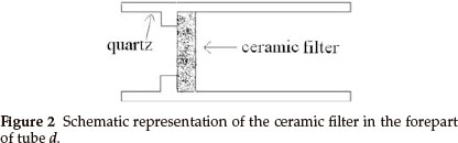
Synthesis of inorganic fullerene-like MoS2 nanoparticles was carried out in a horizontal gas-phase reactor lying in a three-zone tube furnace. The reactor, consisting of four quartz tubes, is depicted in Fig. 1. Tubes a and b served for sublimation of S (sulfur) and MoO3 powders in the argon (Ar) atmosphere. S and MoO3 powders were placed in two small quartz boats (boats 1 and 2) inside tubes a and b, respectively. The heated S and MoO3 powders were sublimed and swept by the Ar stream into the tube c through several pinholes in tubes a and b (see Fig. 1), in which the reaction took place. Tube d was used for gas exit. The reaction products were collected on a ceramic filter in the forepart of tube d (as shown in Fig. 2).
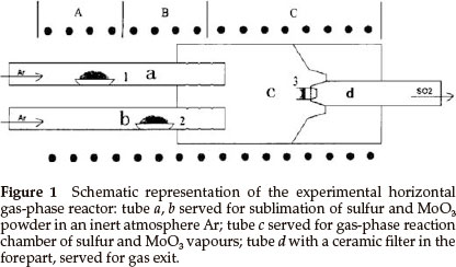
Typical experimental procedures were as follows: quartz boats 1 and 2 with S (22.4 g) and MoO3 (2.9 g) powders were positioned in zone A and B of a three-zone tube furnace, respectively. Highly pure argon gas (>99.999 %) was passed through the tubes in order to remove atmosphere and steam in the reactor, then a gas flow meter was adjusted to the required argon flow rate when zone C was heated to 550 °C with heating rate 10 °C min-1; finally the temperatures of zones A, B and C reached and were maintained at 420 °C, 650 °C and 840 °C, respectively, for 120 min. The reactor was cooled to room temperature in argon atmosphere and then black MoS2 powders were collected on a ceramic filter for analysis.
Structural characterization of products was analyzed by an X-ray powder diffractometer (XRD; RIGAKU D/max-2400, Tokyo, Japan) with Cu kα radiation (λ = 0.15418 nm) at 40 kV, 200 mA. The morphology, structure and composition of the samples were determined using a scanning electron microscopy (SEM; S-3400N, Hitachi, Tokyo, Japan) and transmission electron microscopy (TEM; JEM-3010, JEOL, Tokyo, Japan) equipped with an energy dispersive X-ray spectrometer (EDX, S-570, Japan) and operated at 200 keV. Raman spectra were taken under ambient conditions using a Renishaw in a Via Raman microscope spectrometer (System-1000, Renishaw, Woburn, MA, USA) excited with a 632.8 nm Ar+ laser.
3. Results and Discussion
In order to obtain pure IF-MoS2 nanoparticles, MoS2 powders were synthesized by MoO3 and S at various reaction temperatures (zone C of tube furnace in Fig. 1). Figure 3 presents the XRD patterns of the products synthesized at 650 °C, 700 °C, 750 °C, respectively, keeping the high pure argon flow rate constant. In addition to MoS2 peaks, the XRD patterns of products include peaks from MoO3 and MoO2 at 650 °C, and MoO2 peaks at 700 °C. Impure products are obtained at both temperatures, comprising MoS2, MoO3 and MoO2 at 650 °C and MoS2 and MoO2at 700 °C. It shows that the reaction does not take place completely, leading to presence of reaction intermediate (MoO2) and raw material (MoO3). No impurity peaks were observed from the XRD spectrum of the products synthesized at 750 °C. All the peaks can be indexed to MoS2, which is in good agreement with the reported value from standard card (JCPDS No. 77-1716). The XRD patterns indicate that very pure MoS2 powders were synthesized at 750 °C. Although reaction of MoO3 and S can occur to form MoS2 at 600 °C,24 it takes a long reaction time to generate MoS2 by the reaction between MoO3 and S gas molecules with low activity at 650 °C, 700 °C. Therefore, the products are not pure MoS2 at lower temperatures (<750 °C). The activity of MoO3 and S sublimations increases with reaction temperature, leading to the generation of pure MoS2 during short time and becoming conformation.
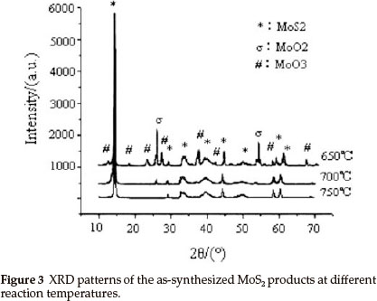
Figure 4 shows a series of SEM images of MoS2 powders synthesized at 800 °C, 840 °C, 870 °C, 900 °C, respectively, keeping the argon flow rate constant. It can be seen that MoS2 crystals with platelet structure obtained at 800 °C, whose shapes were principally quasi-round or regular hexagon, are uniform and loose nanoparticles with size about 150-300 nm (Fig. 4a). At 840 °C, MoS2 nanoparticles with quasi-sphere structure are synthesized, with sphere diameter of approximately 60-90 nm (Fig. 4b). MoS2 nanoparticles with quasi-sphere structure were observed as well at 870 °C (Fig. 4c), with diameter about 200 nm, which is greater than that of products obtained at 840 °C. At 900 °C, reaction products are MoS2 nanoparticles with similar shape to that synthesized at 800 °C, the diameters of the nanoparticles are larger than that of samples synthesized below 900 °C. Meanwhile, a MoS2 micrometer particle, with diameter around 2000 nm, was observed (arrow in Fig. 4d), it might be formed of MoS2 nanosheets interconnecting. The experimental results above demonstrate that the diameters of MoS2 nano-particles with same structure (platelet or sphere) may increase with reaction temperature.
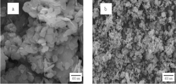
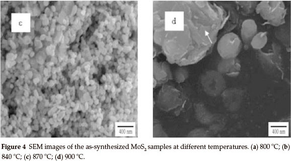
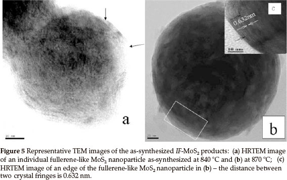
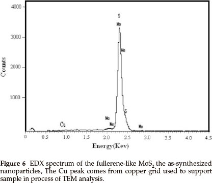
Figure 5a is a HRTEM image of a randomly chosen single IF-MoS2 nanoparticle synthesized at 840 °C from MoO3 and S powders. The diameter of the IF-MoS2 nanoparticle is about 60 nm, and the crystal lattice is similar to structure of fullerene C60, consisting of a series of empty spheres with different diameters. Figure 5b presents a TEM image of an optional individual MoS2 nanoparticle obtained at 870 °C. Because of the diameter of the nanoparticle being too large (about 220 nm), the entire lattice structure of the IF-MoS2 nanoparticles is hardly displayed. The fringe structure of the marginal part (the box diagram at the bottom left corner in Fig. 5b) of the IF-MoS2 nanoparticle is displayed in Fig. 5c (the inset HRTEM image at the top right corner in Fig. 5b).We can see that MoS2 layers terminate and layers dislocate (black arrow in Fig. 5a and Fig. 5c); generally, it is attributed to the formation of defects of the MoO3 precursor nano-particles or the short-term shortage of supply of raw materials in IF-MoS2 nanoparticles formation process.4,25 Simultaneously, crystal lattice fringe of MoS2 nanoparticles with fullerene-like (IF-MoS2) is 0.632 nm (the distance between white arrows in Fig. 5c), which is larger than the value of 2H-MoS2 (0.612 nm). The lattice expansion is about 3.2 %, which is attributed to the less strain in the bent MoS2 layers. Energy dispersive X-ray (EDX) spectrum measurement was used to characterize the overall chemical composition of the IF-MoS2 nanoparticle, and the result is shown in Fig. 6. Strong peaks associated with S and Mo are found in the spectrum. The Cu signal comes from copper grid used to support sample in the process of TEM analysis. Quantitative analysis shows thatMo: S is about 1:2.02, consistent with atomic ratio of MoS2 structure, which proves that the synthesized products are IF-MoS2 nanoparticles.
IF-MoS2 nanoparticles are generated by sulfidization of suboxide MoO3-x nanoparticles,4 which are products of partial reduction of the molybdenum trioxide molecular clusters. According to the model, a synergy between the reduction and the sulfidization processes which occurs in a very narrow window of parameters is necessary, if not, the 2H-MoS2 would form.25-27 Reaction temperature plays an important role in synthesizing fullerene-like MoS2(IF-MoS2) nanoparticles. The precursor MoO3molecular cluster is composed of two octahedra connected via a corner oxygen atom. While MoO3 molecular clusters are reduced into MoO3-x nanoparticles, a few oxygen atoms leave the octahedron, and oxygen vacancies are thus formed. Lower critical concentration (threshold value) of vacancy is required for the shear process to occur at higher temperature. The induction period for generation of threshold concentration of vacancy on the crystallite surface decreases with temperature. At lower temperatures (800 °C), the rate of the shear process (reduction) is slow compared with sulfuring by the vacancy and consequently sulfur trapping predominates. At higher temperatures (900 °C), the rates of both the shear process and sulfur trapping increase with temperature, the former one predominates. At intermediate temperatures (840-870 °C), the rates of both processes have the same order of magnitude and, moreover, sulfidization and shear appear at the same time, leading to the formation of inorganic fullerene-like MoS2.
The experimental results show that diameters of IF-MoS2 nanoparticles increase with reaction temperature. MoS2 layer formed in the process of partial reduction of MoO3nanoparticles is chemically inert and prevented MoO3 nanoparticles from growing further, therefore the IF-MoS2 nanoparticles diameters are determined by that of precursor MoO3 nanoparticles.28 The vapour phase of MoO3 consists predominantly of the molecular clusters Mo3O9,Mo4O12 and Mo5O15.29 The cluster Mo3O9, which has a hexagonal ring structure, is the most stable one, and consequently, it is the most volatile cluster of the three. In the next step, these clusters condense into MoO3 nanoparticles. At a lower temperature, volatilization of MoO3 powder is slower, (MoO3)3 molecular clusters concentration in tube b is lower. Due to smaller collision probability of the molecular clusters, the diameters of precursor MoO3 nanoparticles condensed by these clusters are minor. Thus, finally obtained IF-MoS2 nanoparticles are smaller. On the contrary, with increasing reaction temperature, MoO3 powder volatilizes quickly, the diameters of MoO3 nanoparticles are accreted, leading to the formation of bigger IF-MoS2 nanoparticles. The diameter of MoO3 nanoparticles precursor converting into IF-MoS2 nanoparticles, however, has a critical value about 300 nm reported by R. Tenne and co-workers.30 Above that value, 2H-MoS2 platelets will be obtained. Therefore, reaction temperature at and above 900 °C the diameters of MoO3 precursor nanoparticles are larger than 300 nm and 2H-MoS2 platelets are synthesized finally. The size of the layered MoS2 nanoparticles obtained at low temperature (800 °C) is larger than that of IF-MoS2 nanoparticles at high temperature (840 °C and 870 °C), which is due to predomination of sulfur trapping at this time.
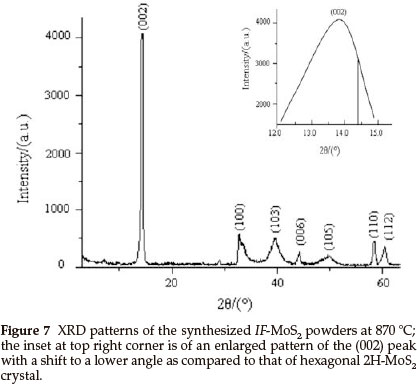
Figure 7 presents the XRD pattern of the IF-MoS2 powder synthesized at 870 °C. We can see that all the diffraction peaks in the XRD spectrum of the sample can be indexed to MoS2, which indicates that the product is pure IF-MoS2. The inset at top right corner is an enlarged pattern of the (002) peak of XRD spectrum of the IF-MoS2 powder with diffraction angle of 12-15 °. The inset pattern displays that (002) peak of IF-MoS2 lies in 13.89 °, that of layered hexagonal 2H-MoS2 is at >14.38 ° (vertical line as shown in the inset pattern),which shows that the position of the (002) peak of IF-MoS2 shifts to a lower angle. The shift indicates a lattice expansion of ca. 3.2 % between two adjacent MoS2 slabs along c-axis, the value is consistent with HRTEM result and larger than that (ca. 2 %) reported in literature.4 It is generally considered that this shift is attributed to the less strain in the bent layers. Furthermore, since the number of atoms in the layers increases with nanoparticles radius, the layers cannot be fully commensurate.26 According to the literature,4,25,26 the shift proves that MoS2 has a fullerene-like structure. The result is in accordance with the conclusions of the HRTEM observation.
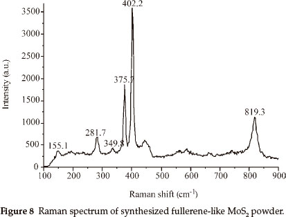
Raman spectrum measured at room temperature of IF-MoS2 powder obtained at 870 °C is shown in Fig. 8, the excitation source used for the argon ion laser with wavelength 632.8 nm. Raman spectrum is the same as those obtained by G.L. Frey,30 and all characteristic peaks are less than 833 cm-1. Two strongest characteristic peaks of synthesized IF-MoS2, at 375.7 cm-1 and 402.2 cm-1, are at lower wave numbers than those (378 cm-1 and 407 cm-1) of samples synthesized by G.L. Frey. They are at 384 cm-1 and 409 cm-1 in 2H-MoS2 spectrum, which correspond to E2g and A1g vibration modes respectively.31 The peaks of 155.1 cm-1, 349.8 cm-1, 281.7cm-1 are absent in bulk and layered 2H-MoS2.31 Raman spectrum of IF-MoS2 obtained by G.L. Frey only exist 283 cm-1 peak, and simultaneously exist 155 cm-1 peak by L.D. Whitby,26 which are attributed to MoS2 layers folding or curling along Γ-M direction of Brillouin zone to form fullerene-like polyhedron and nanotube.26 This is strong evidence that MoS2 samples obtained in our experiments have inorganic fullerene-like structure. All wave numbers of characteristic peaks of the samples are lower than that reported previously, that may be attributed to differences in experimental conditions.
R. Tenne and co-workers think fullerene-like MoS2 nano-particles and nanotubes are formed by reacting the MoO3 vapour with H2S in the reduction atmosphere (5 % H2 + 95 % N2) step by step, reaction equations can be described by4,24,25
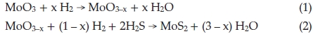
In our approach, large amounts of fullerene-like MoS2 nano-particles were synthesized through reaction of MoO3 precursors with sulfur vapour, in which S, instead of H2S and H2, is both reducing agent and sulfuring agent, the overall reaction equation is

Notwithstanding exact formation mechanism of synthesizing IF-MoS2 nanoparticles using MoO3 and S sublimations is still unclear, the synthesis method is contrasted with the reaction of MoO3 and H2SinH2 atmosphere, synthesized products are also including MoO2, considering the literature4,24,26,32 and experiment results, we infer the formation of IF-MoS2 nanoparticles synthesized reacting the MoO3 vapour with H2Sis also the result of reduction and sulfuration. Possible reaction equations can be described as follows
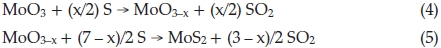
where 0.1 < x <0.5. In the process of synthesis, MoO3 precursors and S vapour are reactants. At lower temperature, incomplete reaction takes place and leads to forming an intermediate product due to the lower the activity of reactants. MoO2 is one of the most stable in Mo compounds, so intermediate product exists generally in form of MoO2. Below 750 °C, we obtained products including MoO2. In Equation (4), if x = 1, the product becomes MoO2, reaction equation is shown as

4. Conclusion
By using MoO3 and S (sulfur) as raw materials, MoS2 nano-particles with inorganic fullerene-like structure were reproducibly obtained by a chemical vapour deposition method as experiment conditions were precisely controlled. Highly pure Ar (argon) gas served as carrier gas in the synthesis process. This method broke though the limitation that corrosive toxic gas H2S or high-priced H2 was unavoidable in the formation of IF-MoS2 nanoparticles and nanotubes. On the basis of previous work and experimental results, a new reaction mode (formation mechanism) has been proposed, which method provides a scale-up and low-cost route to synthesizing IF-MoS2 nanoparticles, laying foundations for further investigation of physical and chemical properties of the IF-MoS2 raw materials. The synthetic approach can be potentially developed into a general method to preparing transition metal chalcogenides with the fullerene-like structure.
Acknowledgements
This work was supported by the National Nature Science Foundation (51172187), the SPDRF and 111 Program (B08040) of MOE of China, the Special Scientific Research project Foundation of the Education Department of Shaanxi Province of China (09JK447), the special foundation item of the key academic subjects development of Shaanxi province [Shaanxi education Supporting (2008)169].
References
1 H.W. Kroto, J.R. Heath, S.C. O'Brien, R. F. Crul and R.E. Smalley, Nature, 1985, 318, 162-164. [ Links ]
2 S. Iijima, Nature, 1991, 354, 56-58. [ Links ]
3 R. Tenne, L. Margulis, M. Genut and G. Hodes, Nature,1992, 360, 444-446. [ Links ]
4 Y. Feldman, E. Wasserman, D.J. Srolovitz and R.Tenne, Science, 1995, 267, 222-225. [ Links ]
5 M. Alaei, A. Rashidi and A. Mahjoub, 7ran. J. Chem. Chem. Eng., 2009, 28, 91-95. [ Links ]
6 H.H. Wu, R. Yang, B.M. Song, Q.S. Han, J.Y. Li, Y. Zhang, Y. Fang, R. Tenne and C. Wang, ACS Nano, 2011, 5, 1276-1291. [ Links ]
7 R. Tenne, M. Remskar, A. Enyashin and G. Seifert, Topics Appl. Physics, 2008, 111, 631-672. [ Links ]
8 L. Rapoport, Yu. Bilik, Y. Feldman, M. Homyonfer, S.R. Cohen, R. Tenne and J. Israelachvily, Nature, 1997, 387, 791-793. [ Links ]
9 L. Rapoport, N. Fleischer and R. Tenne, J. Mater. Chem., 2005, 15, 1782-1788. [ Links ]
10 J.J. Hu and J.S. Zabinski, Tribol. Lett., 2005, 18, 173-180. [ Links ]
11 Y.Q. Zhu, T. Sekine, Y.H. Li, M.W. Fay, Y.M. Zhao, C.H.P. Poa, W.X. Wang, R. Martin, P.D. Brown, N. Fleischer and R. Tenne, J. Am. Chem. Soc., 2005, 127, 16263-16272. [ Links ]
12 A. Kis, D. Mihailovic, M. Remskar, A. Mrzel, A. Jesih, I. Piwonski, A.J. Kulik, W. Benoit and L. Forro, Adv. Mater., 2003, 15, 733-735. [ Links ]
13 R. Dominko, M. Gaberscek, D. Arcon, A. Mrzel, M. Remskar, D. Mihailovic, S. Pejovnik and J. Jamnik, Electrochim. Acta, 2003, 48, 3079-3084. [ Links ]
14 J. Chen, S.L. Li and Z.L. Tao, J. Alloys Compd., 2003, 356, 413-417. [ Links ]
15 H. Friedman, O. Eidelman, Y. Feldman, A. Moshkovich, V Perfiliev, L. Rapoport, H. Cohen, A. Yoffe and R. Tenne, Nanotechnology, 2007, 18, 115703-115711. [ Links ]
16 I. Kaplan-Ashiri, S.R. Cohen, K. Gartsman, V. Ivanovskaya, T. Heine, G. Seifert, I. Kanevsky, H.D. Wagner and R. Tenne, Proc. Natl. Acad. Sci., 2006, 103, 523-528. [ Links ]
17 J. Chen, S.L. Li, Q. Xu and K.J. Tanaka, Chem. Commun., 2002, 16, 1722-1723. [ Links ]
18 S.T. Wang, C.H. An and J.K. Yuan, Materials, 2010, 3, 401-403. [ Links ]
19 P. A. Parilla, A.C. Dillon, K.M. Jones, G. Riker, D.L. Schulz, D.S. Ginley and M.J. Heben, Nature, 1999, 397, 114-114. [ Links ]
20 J. Tannous, F. Dassenoy, I. Lahouij, T.L. Mogne, B. Vacher, A. Bruhács and W. Tremel, Tribol. Lett., 2011, 41, 55-64. [ Links ]
21 A.N. Enyashin, S. Gemming, M. Bar-Sadan, R. Popovitz-Biro, S.Y. Hong, Y. Prior, R. Tenne and G. Seifert, Angew. Chem. 7nt. Ed. Engl., 2007, 46, 623-627. [ Links ]
22 WK. Hsu, B.H. Chang, Y.Q. Zhu, W.Q. Han, H. Terrones, M. Terrones, N. Grobert, A.K. Cheetham, H.W. Kroto and D.R.M. Walton, J. Am. Chem. Soc., 2000, 122, 10155-10158. [ Links ]
23 N. Sano, H.L. Wang, M. Chhowalla, I. Alexandrou, G.A.J. Amaratunga, M. Naito and T. Kanki, Chem. Phys. Lett., 2003, 368, 331-337. [ Links ]
24 Y. Feldman, G.L. Frey, M. Homyonfer, V. Lyakhovitskaya, L. Margulis, H. Cohen, G.Hodes, J.L. Hutchison and R. Tenne, J. Am. Chem. Soc., 1996, 118, 5362-5367. [ Links ]
25 Y. Feldman, V. Lyakhovitskaya and R. Tenne, J. Am. Chem. Soc., 1998, 120, 4176-4183. [ Links ]
26 R.L.D. Whitby, W.K. Hsu, P.K. Fearon, N.C. Billingham, I. Maurin, H.W. Kroto, D.R.M. Walton, C.B. Boothroyd, S. Firth, R.J.H. Clark and D. Collison, Chem. Mater., 2002, 14, 2209-2217. [ Links ]
27 A. Margolin, R. Rosentsveig, A. Albu-Yaron, R. Popovitz-Biroand and R. Tenne, J. Mater. Chem., 2004, 14, 617-624. [ Links ]
28 Y. Feldman, A. Zak, R. Popovitz-Biro and R. Tenne, Solid State Sci., 2000, 2, 663-672. [ Links ]
29 A. Zak, Y. Feldman, V. Alperovich, R. Rosentsveig and R. Tenne, J. Am. Chem. Soc., 2000, 122, 11108-11116. [ Links ]
30 G.L. Frey, A. Rothschild, J. Sloan, R. Rosentsveig, R. Popovitz-Biro and R. Tenne, J. Solid State Chem., 2001, 162, 300-314. [ Links ]
31 G.L. Frey, R. Tenne, M.J. Matthews, M.S. Dresselhaus and G. Dressel-haus, Phys. Rev. B, 1999, 60, 2883-2892. [ Links ]
32 R. Rosentsveig, A. Margolin, A. Gorodnev, R. Popovitz-Biro, Feldman, Y. L. Rapoport, G. Naveh and R. Tenne, J. Mater. Chem., 2009, 19, 4368-4374. [ Links ]
Received 31 December 2012
Revised 6 September 2013
Accepted 13 September 2013
* To whom correspondence should be addressed. E-mail: gaobin7401@sina.com

