


Serviços Personalizados
Artigo
 Inglês (pdf)
 Artigo em XML
 Referências do artigo
Indicadores

Links relacionados
-
 Citado por Google
 -
 Similares em Google
Compartilhar

 Permalink
South African Journal of Chemistry
versão On-line ISSN 1996-840X
versão impressa ISSN 0379-4350
S.Afr.j.chem. (Online) vol.66 Durban Ago. 2013
RESEARCH ARTICLE
Decoration of multi-walled carbon nanotubes by metal nanoparticles and metal oxides using chemical evaporation method
Pheladi M. Masipa*; Takalani Magadzu; Bridget Mkhondo
Department of Chemistry, University of Limpopo (Turfloop campus), Private Bag X1106, Sovenga, Polokwane, 0727, South Africa
ABSTRACT
The powder patterns of the as-prepared and acid treated MWCNTs are shown by the XRD spectra. The TEM results show the microstructure of the multi-walled carbon nanotubes well decorated with metal nanoparticles (Cu, Fe, Ni) and metal oxides (CuO, Fe2O3 NiO), while the SEM show the surface morphology.
Keywords: Multi-walled carbon nanotubes, metal nanoparticles, metal oxides, scanning electron microscopy, transmission electron microscopy.
1. Introduction
Carbon nanotubes (CNTs) have been proposed as the ideal metal catalyst support for electrocatalytic and sensing applications because of their unique electrical properties, high chemical stability and high surface-to-volume ratios.1 Decoration of the walls of carbon nanotubes (CNTs)2 with functional groups3 and/or nanoparticles has been performed to add additional functionality to CNTs. In recent years, decoration of CNTs has been used to improve performance of their various applications4 such as making nanotubes magnetic,5 to grow secondary structures inside the nanotubes to increase the available surface for catalysis6 or in electronics.7 Modern electronics devices based on carbon nanotubes (CNTs) have shown that their performance is influenced by a potential barrier existing at the metal-CNT contact that governs the electron injection into the carbon nanotubes.7
To functionalize the CNTs with metal nanoparticles, an ionic adsorption followed by a direct heating can be adopted. This procedure involves the mixing of CNTs with a known concentration of metal nitrate, and then stirred under argon (Ar) atmosphere at a certain temperature for a known period of time. This wet process enables metal ions to interact with the surface oxygen groups, forming metal adsorbed on the CNTs surface. Then, the metal adsorbed CNTs tend to be separated from the metal-salt solution by using a filtration apparatus. The direct heating process can be performed at high temperature under mixed H2/Ar (1/99 in v/v) atmosphere, ensuring reduction of metal oxides to metal particles.8-10In electrochemistry, electrode position method is the most common method to decorate CNTs by metal nanoparticles and metal oxides due to being economic and easy to use.
Bittencourt and co-workers reported the decoration of CNT with nickel nanoparticles using thermal evaporation method.11 It was found that CNT decorated with Ni varies from well-organized clusters to complete coverage of the surface resulting in electronic charge transfer and formation of Ni-C bond. There is a very limited publication regarding decoration of CNTs by metal oxides and metal nanoparticles by chemical evaporation method. As a result, we were prompted to further study and investigate the efficiency and effectiveness of using the chemical
In this work we present the XRD spectrum of the as-prepared CNTs. TEM and SEM results of metal nanoparticles(Cu, Fe, Ni) and metal oxides (CuO, Fe2O3 NiO) decorated on the surface of the oxidized MWCNTs by the chemical evaporation method are also depicted. The elemental analysis of the metal nanoparticles and metal oxides decorated MWCNTs are displayed by the EDS spectra.
2. Experimental
2.1. Preparation of Carbon Nanotubes
Multi-walled carbon nanotubes were prepared by pyrolysis of 0.31 g of iron (II) phthalocyanine (90 %, Aldrich) which was placed in a boat in the middle of the quartz glass tube. Prior and during pyrolysis, a controlled flow of Ar/H2 (3:1 v/v, 40 mL min-1) mixture was introduced into the quartz tube. Sample was heated by Lenton furnaces with three independent temperature controllers. The middle furnace was adjusted to a pyrolysis temperature of 900 °C. The temperature ramping rate recorded ranges between 20.3 °C min-1 to 20.8 °C min-1, depending on the room temperature. After the furnace has reached 900 °C, the furnace was kept at this temperature for an additional 30 min (pyrolysis time) for deposition of multi-walled carbon nanotubes to be completed. The CNTs formed were scraped from the boat and quartz tube as a black powder.12
2.2. Purification of Carbon Nanotubes
The as-prepared carbon nanotubes were purified by refluxing with a mixture of HNO3 (55 %, uniLAB) and H2SO4 (95 %, Fluka) using a 1:3 ratio at 80 °C for 30 min (the exposure time was chosen in order to minimize tube damage). Thereafter, the mixture was diluted with water and filtered while washing with distilled water (about 900 mL). Washed carbon nanotubes were dried at 80 °C for 4 h.13
2.3. Preparation of Metal Nanoparticles
Metal nanoparticles (Cu, Fe and Ni) were prepared by employing the reduction method using sodium borohydride as the reducing agent in a 1:1 v/v. A concentration of 0.1 M metal nitrate solution was prepared and a 0.2 M solution of sodium borohydride (NaBH4) was added drop-wise while stirring the mixture at a controlled rate of 100 rpm to give a size and shape controlled metal nanoparticles. After a drop-wise addition of sodium borohydride, the metal nitrate solution was allowed to stir for an additional 30 min to allow for a complete formation of metal nanoparticles. After formation of the nanoparticles, they were filtered and washed with 900 mL of distilled water and thereafter dried at 80 °C for 4 h. It is worth mentioning that it was of interest to synthesize nanoparticles with a desired optical, magnetic, electrical, surface area and catalytic properties for successful application in gas storages, sensors and high performance nanoscale device.14,15 All solutions were prepared using de-ionized water.
2.4. Preparation of Metal Oxides
Metal oxides (CuO, Fe2O3 NiO) were prepared from the respective metal nitrate source by heating in air at 400 °C for 2 h. High temperature treatment results in decomposition of nitrate group (NO3) from the metal source with water molecules evaporat-ing.16 The typical chemical oxidation reaction for preparation of metal oxides is as follows:

2.5. Decoration of Multi-walled Carbon Nanotubes
Approximately 2 mg of metal nanoparticles or metal oxides were mixed with approximately 2 mg of MWCNTs and 2 mL of N, N-Dimethylformamide (DMF, 99.5 % assay, Saarchem) as the binder. The nanocomposites were sonicated to allow the mixture to dissolve which subsequently resulted in metal nanoparticles or metal oxides being well coated on the surface of the oxidized MWCNTs. A similar procedure was employed by Rao el al.17 The known volume of the putty form of the MWCNT-M (M = metal nanoparticles or metal oxides) nanocomposites was dried at 25 °C for overnight for the solvent to evaporate.17
2.6 Characterization of Carbon Nanotubes, Metal Nano-particles and Metal Oxide Decorated Carbon Nanotubes
2.6.1. X-ray Diffraction (XRD) Spectroscopy Analysis
X'pert Pro X-ray spectroscopy instrument from PAN analytical was used to determine the structure of the as-prepared carbon nanotubes. The following XRD experimental analysis method was employed:
Wavelength of Cu K alpha radiation used was 1.5406 Ǻ with 2 theta = 5-100 ° and exposure time of 15 min s-1. The Step size was 0.026 ° and the Time/Step was 61.2 s at a scan speed of 0.109 ° s-1.
The x-ray spectroscopy measurement provided not only structural characterization CNTs but also information about the presence and absence of the catalytic particles in the unpurified and purified sample.18
2.6.2. Transmission Electron Microscopy (TEM) Analysis
A JEOL 2100 transmission electron microscopy (TEM) with a 200 k acceleration voltage and LaB6 filament was used in bright field mode to determine the micro-structure of the metal nanoparticles and metal oxides decorated carbon nanotubes.
2.6.3. Scanning Electron Microscopy (SEM) Analysis
A JEOL 7500 scanning electron microscopy (SEM) was used to determine the powder morphology and microstructure of the sample. This technique was used to scan the dry surface of the material where one is only interested in the surface details.
2.6.4. Energy Dispersive X-ray Spectroscopy (EDS) Analysis
A JEOL 7500 SEM fitted with a Thermo NORAN SDD energy dispersive detector was used to determine the chemical composition of the prepared metal nanoparticles and metal oxides decorated multi-walled carbon nanotubes. Samples were mounted sparingly on double-sided carbon adhesive tape, and subsequently coated lightly with carbon (about 4 nm thickness) to render them conductive. Each sample was analysed with a 15 k electron beam in three areas chosen at random.
3. Results and Discussion
3.1. X-ray Diffraction (XRD) Results
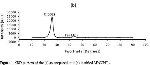
Figure 1 shows the powder XRD patterns (Cu Kα λ = 1.5406 Ǻ) of the 1(a) as-synthesized and 1(b) purified MWCNTs. The peaks for the as-prepared MWCNTs arrays are indexed to (002), (111) and (200) reflections of hexagonal graphite and catalytic impurities, similar to the XRD pattern of the as-prepared MWCNTs studied by Mahanandia et al.19. The (110) and (200) peaks show the presence of iron (from the iron (II) phthalocyanine used as source) used as catalyst during MWCNTs synthesis. From the XRD pattern of the purified MWCNTs in Fig. 1(b), there is a significant decrease in the amount of iron nanoparticles impurities. The XRD spectrum of the purified MWCNTs also shows the absence of amorphous carbon or hexagonal graphite impurities. This suggests a successful and effective removal of impurities from the surface of the MWCNTs by acid treatment method employed, making MWCNTs suitable for various applications.

3.2. Transmission Electron Microscopy (TEM) Analysis
TEM images of MWCNTs-Cu and MWCNTs-CuO are illustrated in Fig. 2. Observations in Fig. 2 clearly reveal a successful decoration of oxidized MWCNTs with (a) Cu and (b) CuO. Decorated images of CuO nanoparticles on the surface of the MWCNTs are shown in Fig. 2(b), where CuO tend to homogenously attach on the external surface of the MWCNTs. The morphology can be described as a uniform layer covering the nanotube surface com-pletely.11
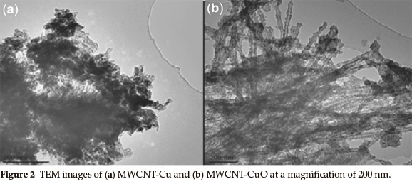
The Metal-CNT interaction was studied by Bittencourt et. al.,11using X-ray photoelectron spectroscopy. It was found that metal-C bond length was larger than the C-C bond in a graphene sheet,20 thus one could expect that the formation of Metal-C bonds perturbs the graphene lattice and affects the distance between the tubes under metal cluster.
Transmission electron microscopy images of MWCNT-Fe and MWCNT-Fe2O3 are depicted in Fig. 3. Figure 3(a) shows MWCNTs decorated with Fe nanoparticles. Figure 3(b) illustrates long MWCNTs well decorated with Fe2O3. The TEM images in Fig. 3(b) clearly shows several particles of Fe2O3 along a strand of MWCNT. It can be seen that the Fe2O3 nanoparticles are highly decorated on the surface of the MWCNTs. Such dispersion is much better than those produced by a conventional electroless deposition method.21

In Fig. 4, TEM images of MWCNT-Ni nanocomposites are illustrated. MWCNTs appear to have open tips at the end as shown by an arrow in Fig. 4(a). Ni nanoparticles are seen as a black powder on the surface of the oxidized MWCNT. Figure 4(b) shows the bamboo-shaped MWCNT as a single long strand. Theoretical studies suggest that Ni atoms on CNT surface interact mainly with vacancies; the energy for substitution of a C atom by a Ni atom in a grapheme sheet was estimated to be 9.5 eV while Ni atom interact with vacancies with a strong adsorption bond of -4.7 eV.20 Based on the results presented it can be suggested that metal nanoparticles and metal oxides decoration of MWCNTs by chemical evaporation involves first the adsorption of metal nanoparticles/oxides atom onto the surface, followed by diffusion of these adatoms across the surface until nucleation of islands occurs when diffusing adatoms form a stable nucleus.

3.3. Scanning Electron Microscopy (SEM) Analysis
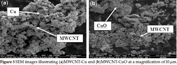
Successful dispersion of the MWCNT in the Cu and CuO matrix was achieved. These nanocomposite powders of MWCNTs dispersed with Cu and CuO nanoparticles are shown by SEM images in Figs. 5(a) and 5(b), respectively. Roro et al.22 also recently studied surface morphology of MWCNTs dispersion in the NiO matrix at a magnification of 1 µm. NiO also appeared to be well dispersed on the surface of the MWCNTs.
Figures 6(a) and 6(b) illustrates the SEM images of the MWCNT-Fe and MWCNT-Fe2O3 nanocomposites, respectively. Some of the Fe2O3 nanoparticles appear to be spherical in shape. The single headed arrow in Fig. 6(a) shows the oxidized MWCNTs with the double headed arrow depicting the Fe nanoparticles. In Fig. 6(b), the single headed arrow also represents MWCNTs with the double headed arrow showing Fe2O3 on the surface of the MWCNTs. SEM results in Fig. 6(a) shows that the chemical evaporation method employed for decoration of MWCNTs by Fe nanoparticles could generate highly uniform Fe nanoparticles on the MWCNTs compared to that produced by the electroless deposition method.21 SEM morphological images of MWCNT-Ni nanocomposite are depicted in Figs. 7(a) and 7(b) at a magnification of 10 µm and 5 µm, respectively. Ni nanoparticles are shown to be well dispersed on the surface of the MWCNTs. This proves that our preparation method is able to make the attached metal oxides and metal nanoparticles uniformly deposited onto MWCNTs.


3.4. Energy Dispersive X-ray Spectroscopy (EDS) Analysis
Decoration of multi-walled carbon nanotubes by Cu nano-particles and CuO is confirmed by energy dispersive X-ray spec-troscopy in Fig. 8. Besides C and Cu signals, EDX spectrum include also signal connected with Fe element in Fig. 8(b). This peak for the Fe element is connected with the presence of remaining catalyst impurities. The Cu nanoparticles seem to be highly concentrated than C of the multi-walled carbon nanotubes.

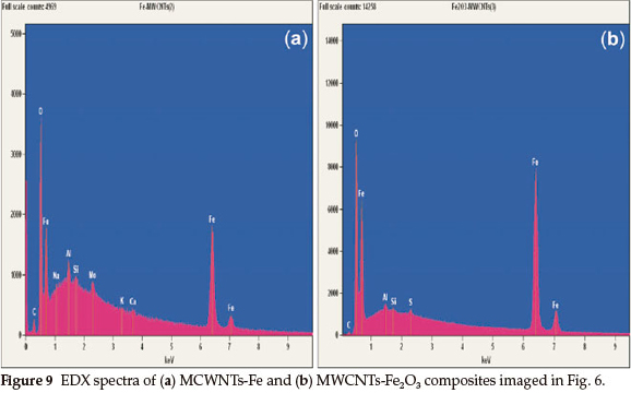
TheFeandFe2O3 phase appearance on the MWCNTs is convincingly confirmed by the EDS spectra in Fig. 9. The C signal is higher as compared to the C signal in Fig. 8. The peak of O element in Fig. 9(a) is connected with the process of functionalization of the MWCNTs. Functionalization improved the deposition of metal nanoparticles and metal oxides onto the MWCNTs for various applications. The functionalized MWCNTs by acid treatment will have carboxylic acid, hydroxides and other functional groups attached to the exterior surface of the MWCNTs, to act as an anchor seeds for metal nanoparticles and metal oxides deposition.23
In Fig. 10 the EDX spectra of 10(a) MWCNT-Ni and 10(b) MWCNTs-NiO nanocomposites reveals the presence of Fe and Fe2O3 ,respectively. The peak of the Fe element is from the catalyst impurity from synthesis of MWCNTs. The presence of Fe nanoparticles signal from the EDX spectra is consistent with the XRD spectra results.

References
1 H. Dai, Chem. Phys. Lett, 2000, 331, 35. [ Links ]
2 T. Ebbesen, J. Phys. Chem., Solids, 1996, 57, 951-955. [ Links ]
3 E.G. Rakov, Nanomaterials Handbook, 2006, 56, 105-175. [ Links ]
4 S.C. Mu, H.L. Tang and S.H. Qian, Carbon, 2006, 44, 762-767. [ Links ]
5 C. Gao, W. Li and T. Maekawa, J. Phys. Chem. B, 2006, 110, 7213-7220. [ Links ]
6 X. Zha,P. Jiang, W. Chu and S. Mu, Carbon, 44, 1310-1313. [ Links ]
7 J. Tersoff, Nature, 2003, 424, 6949. [ Links ]
8 Y. Lu, H. Fan, A. Stump, T.L. Ward, T. Rieker and C.J. Brinker, Nature, 1999, 398, 223-226. [ Links ]
9 J. Zhu, M. Yudasaka, M. Zhang, D. Kasuya and S. Iijima, Nanotech. Lett., 2003, 3, 1239-1243. [ Links ]
10 E. Leontidis, M. Orphanou, T. Kyprianidou-Leodidu, F. Krumeich and W. Caseri, Nanotech. Lett, 2003, 3, 569-572. [ Links ]
11 C. Bittencourt, A. Felten, J. Ghijsen and J.J Pireaux, Chem. Phys. Lett., 2007, 436, 368-372. [ Links ]
12 Z.Bin,C.RobertandH.Hui, J.Phys. Chem. B,2003, 107,13838-13842. [ Links ]
13 M.M. Shaijumon, N. Rajalakshmi, H. Ryu and S. Ramaprabhu, Nanotech., 2005, 16, 518-519. [ Links ]
14 W.J. Zhang, Nanopart. Rep, 2003, 5, 323-326. [ Links ]
15 C. Wang and W. Zhang, Env. Sci. Techn, 1997, 31, 2154-2157. [ Links ]
16 D. Jong and P. Xiao, J. Phys. Chem, 2005, 117, 134-137. [ Links ]
17 C.N.R. Rao and G. Gautam, J. Mat. Chem., 2003, 13, 209-213. [ Links ]
18 X. Wang, W. Hu, Y. Liu and S. Zhou, Carbon, 2001, 39, 1533-1539. [ Links ]
19 P. Mahanandia and K.K. Nanda, Nanotech, 2008, 19, 155-156. [ Links ]
20 F. Banhart, J.C. Charlier and P.M. Ajayan, Phys. Rev. Lett, 2000, 84,684. [ Links ]
21 K. Lee, J. Zhang, H. Wang and D. Wilkinson, J. Appl. Electrochem., 2006, 36, 507-522. [ Links ]
22 K.T. Roro, N. Tile, B. Mwakikunga, B. Yalisi and A. Forbes, Mat. Sci. Engn. B, 2012, 177, 581-587. [ Links ]
23 M. Pawlyta, A. Krzton, L.A. Dobrzanski and B. Liszka, J. Achiev. Mat. Manufact. Engn., 2010, 39, 184-189. [ Links ]
Received 12 June 2012
Revised 25 July 2012
Accepted 28 May 2013
* To whom correspondence should be addressed. E-mail: pheladimasipa@gmail.com evaporation method to decorate MWCNTs by metal nanoparticles and metal oxides

