


Serviços Personalizados
Artigo
 Inglês (pdf)
 Artigo em XML
 Referências do artigo
Indicadores

Links relacionados
-
 Citado por Google
 -
 Similares em Google
Compartilhar

 Permalink
South African Journal of Chemistry
versão On-line ISSN 1996-840X
versão impressa ISSN 0379-4350
S.Afr.j.chem. (Online) vol.66 Durban Ago. 2013
RESEARCH ARTICLE
Palygorskite hybridized carbon nanocomposite as a high-performance electrocatalyst support for formic acid oxidation
Keliang WangI; Hui WangI; Rongfang WangI, *; Julian KeyII; Vladimir LinkovII; Shan JiII, **
IKey Laboratory of Eco-Environment-Related Polymer Materials, Ministry of Education of China, College of Chemistry and Chemical Engineering, Northwest Normal University, Lanzhou 730070, China
IISouth African Institute for Advanced Materials Chemistry, University of the Western Cape, Cape Town, 7535, South Africa
ABSTRACT
A nanocomposite, in which acid-treated palygorskite was hybridized with carbon, was prepared and designed as an efficient support for electrocatatlysts. Pd nanoparticles were deposited on the hybrid support as an electrocatalyst for formic acid oxidation. The hybrid supports and electrocatalysts were characterized by X-ray diffraction (XRD), transmission electron microscopy (TEM) and X-ray photoelectron spectroscopy (XPS). TEM and XRD results showed that acid treatment had an effective impact on the morphology of palygorskite, but did not destroy its architecture. XPS results indicated that the introduction of palygorskite resulted in a negative shift of binding energy of Pd deposited on it. The electrochemical results showed that the addition of palygorskite into the carbon facilitated the formation of OHads or Oads on the surface of Pd/C-PLS, and further improved the formic acid electrooxidation activity. Therefore, considerable improvements in electrocatalytic activity toward formic acid oxidation was achieved by using this hybrid support when compared with conventional carbon support, suggesting that the introduction of SiO2-based porous palygoriskite was an excellent and cost-efficient way to improve the electrocatalytic performance of carbon support.
Keywords: Palygorskite, electrocatalyst, composite support, formic acid electrooxidation.
1. Introduction
Recently, it was reported that Pd nanoparticles possessed better electrochemical activity toward formic acid oxidation than the conventional Pt-based electrocatalysts in a half cell, which resulted in a rapid development of Pd-based electro-catalysts for direct formic acid fuel cells (DFAFCs).1-4 It is well-known that the electrocatalytic activity of noble metal nanoparticles is strongly dependent on the nature of their support for electrocatalysts of fuel cells. Currently, carbon-based materials still dominate the supports of electrocatalysts for DFAFCs, due to their high electronic conductivity, porous morphology (to transport educts, fuel and oxidant), and stability in the harsh working conditions of fuel cells.5-9 However, as the support of noble metal catalysts, the carbon corrodes too rapidly in the harsh working conditions of fuel cells, i.e. low pH, high potential, existence of the precious metal particles and on/off operation conditions. Therefore, significant effort has been put into the development of highly stable carbon support materials to improve the stability of support and performance of noble metal particles deposited on their surface.10-12
Some researchers found that modifying the surface of the carbon support with oxides, such as Fe2O3, SnO2 and SiO2, also can efficiently improve the electrocatalytic activities and stability of noble metallic particles deposited on its surface.13-16 Palygorskite (PLS) is a SiO2 based, neutral, tri-octahedral, clay with channels that together with sepiolite form the group of fibrous clay minerals that exhibit pore-like structure. Owing to their sorptive and porous properties, PLS and its derivatives are widely used as active, and specific adsorbents17, catalyst supports18, fire-retardant painting materials19, or templates for the preparation of carbon nanofibers20. Compared with porous carbon materials, PLS is much cheaper due to its accessibility and abundance. In addition, PLS is more chemically inert and environmentally friendly.21 If there is a way to improve the electric conductivity of PLS, PLS will be a potential candidate as a support for noble metal nanoparticles to improve their electrocatalytic activities and stability.
In our previous study22, an electrocatalyst support based on nitrogen-doped graphitic layer coated palygoriskite, was developed by carbonizing polypyrrole, and evaluated as a cathode electrocatalyst support for oxygen reduction reaction (ORR). After Pt nanoparticles were deposited on its surface, the carbon coated palygoriskite exhibited superior catalytic performance for ORR to the conventional Pt/C catalysts. However, carbonization of polypyrrole to prepare carbon-coated palygoriskite is expensive and complicated. In this paper, the objective was to develop a simple and low-cost method of preparing a palygor-skite hybridized carbon nanocomposite support (C-PLS) for an electrocatalyst. Herein, a hybrid support consists of electrically conductive carbon and PLS was developed using acid-treated PLS and commercial carbon. Subsequently, Pd nanoparticles were deposited on its surface by conventional borohydride reduction method. X-ray diffraction (XRD), transmission electron microscopy (TEM), X-ray photoelectron spectroscopy (XPS), nitrogen adsorption-desorption isotherm measurements and cyclic voltammograms (CVs) were used to investigate the effect of PLS on the morphology and electrocatalytic behaviours of the synthesized Pd/C-PLS catalysts.
2. Experimental
Palygorskite was obtained from the Jiangsu Xuyi Jiuchuan Nanomaterial Co. Ltd. Prior to screening with a 200 mesh sieve, it was milled with an agate mortar. The milled PLS was immersed into a 3 mol L-1 hydrochloric acid solution (HCl), and stirred for 4 h; then filtered and dried at room temperature. The synthetic procedure using conventional borohydride reduction method is described below. Vulcan XC-72R and PLS (ratio of C/PLS is 9:1) are slowly added into ethylene glycol (EG, Aladdin Chemistry Co. Ltd) under vigorous stirring to make the mixture well dispersed in the solvent. 30.0 mg of PdCl2 was transferred into a 100 mL flask, and 2 drops of concentrated HCl was added to the flask, and then the mixture was treated in ultrasonic bath for several min. After that, the PdCl2 mixture and 25 mL of ethylene glycol were introduced into above carbon-PLS suspension under stirring. The above mixture was sonicated for 30 min and its pH was adjusted to 9 by addition of 5% of KOH/EG solution. Subsequently, the mixture was transferred into an autoclave and heated at 160 °C for 5 h. The product was collected by filtration, rinsed with deionized water for 10 times and dried overnight in a vacuum oven. For comparison, Pd/C with the same metal loading was synthesized using the same procedure of synthesizing Pd/C-PLS, in which only carbon was used as support.
The catalysts were characterized by recording their XRD patterns on a Shimadzu XD-3A (Japan), using filtered Cu-Ka radiation. All XRD patterns were analyzed using Jade 7.5 of Material Data, Inc. (MDI): peak profiles of individual reflections were obtained by a nonlinear least-square fit of the Cu Kα corrected data. TEM measurements were carried out on a JEM-2010 Electron Microscope (Japan) with the acceleration voltage of 200 kV. The Brunauer-Emmett-Teller (BET) surface area of the catalyst supports were measured by Quantachrome Autosorb-1 volumetric analyzer in the relative range (P/P0)of 0.05-0.30. XPS (Thi-5702 America) was a monochromatic Al Kα X-ray source (hv = 29.35 eV). The electrochemical measurements of catalysts were performed using an Autolab electrochemical work station (PGSTAT128N). A common three-electrode electrochemical cell was used for the measurements. The counter and reference electrode were a platinum wire and an Ag/AgCl (3 mol L-1 KCl) electrode, respectively. The working electrode was a glassy carbon disk with a diameter of 5 mm. The thin-film electrode was prepared as follows: 5 mg of catalyst was dispersed ultrasonically in 1 mL Nafion/ethanol (0.25% Nafion) for 15 min. Subsequently, 8µL of the dispersion was transferred onto the glassy carbon disk using a pipette, and then dried in the air. The catalysts were characterized by CVs and chrono-amperometry (CA) tests at room-temperature. Before each measurement, the solution was purged with high-purity N2 gas for at least 30 min to ensure O2-free measurements. All the electrochemical tests were carried out at ambient temperature.
3. Results and Discussion
The molecular formula of the PLS used in this work was (Mg,Al)5(Si,Al)8O20(OH)2-8H2O. Porous crystalline structures containing tetrahedral layers aligned together with longitudinal sideline chains are the typical reported structure of PLS23. This structure consists of a representative unit cell with Al and Mg cations that can be easily exchanged with other cations or washed out by acid. Fig. 1 shows the change of PLS structure after the acid treatment.

The XRD patterns of the untreated and treated PLS are presented in Fig. 2, indicating that the PLS structure is not destroyed by the acid treatment. Both XRD patterns show that natural and acid-treated PLS possess a high degree of crystallinity. The interlayer distance of the peak at 2θ = 8.3 ° is attributed to the basal space of the PLS framework and usually recognized as the characteristic peak for PLS. The peaks at 13.9 °, 16.5 ° and 20.9 ° represent the Si-O-Si crystalline layers of the clay.24 Quartz impurities were also detected as shown by the peak at 26.7 °. Comparison of the XRDs suggests that acid treatment does not result in any significant loss in the crystallinity of the materials or damage to the PLS architecture. In addition, the quartz impurities cannot be completely removed by the acid treatment, but the peak of carbonate mineral impurities observed at 30.8 ° disappeared after the acid treatment. After the acid treatment, the Al and Mg cations (leached away by acid) could be replaced by H+ to form hydroxyl.

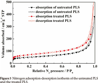
To investigate the effect of acid treatment on pore structure and properties of the PLS, the measurements of nitrogen adsorption-desorption isotherms (Fig. 3) were conducted. Nitrogen adsorption-desorption of natural PLS and acid-treated PLS correspond to type II in the IUPAC classification with a small hysteresis loops. The value of surface area for natural PLS and acid-treated PLS calculated by application of BET equation are 183 m2 g-1 and 254 m2 g-1, respectively. Here, the enhancement of surface area after acid treatment can be attributed to the elimination of octahedral cations and formation of rough surface.25
TEM images of natural PLS, acid -treated PLS, Pd/C and Pd/C-PLS are shown in Fig. 4. It can be seen that PLS and acid-treated PLS exhibit a tube-like morphology. Comparing Fig. 4a and Fig. 4b, the major difference of these two TEM images is that bundled tubes are observed in the sample of natural PLS, whereas the tubes are more separated in the TEM of acid-treated PLS. In the natural PLS, there are some impurities, such as Al2O3, CaO and MgO, which may exist in both the tetrahedral Si-O sheets and the surface of PLS tubes. These impurities on the surface of PLS tubes might bond the tubes together, but might also break after acid treatment. Fig. 4c and Fig. 4d present TEM image and the corresponding Pd nanoparticle size distribution of Pd/C, respectively. Pd nanoparticles can be seen dispersed on carbon support with obvious agglomeration. The Pd nanoparticles exhibit diameters ranging from 4.0 to 6.5 nm and its average diameter is 5.2 nm as shown in Fig. 4d. Fig. 4e and Fig. 4f illustrate the morphology and nanoparticle size distribution of Pd/C-PLS, respectively. Fig. 4e reveals that PLS are mixed with carbon and the black Pd nanoparticles can be seen on the surface of C. The range of nanoparticle diameter is from 4.0 to 6.5 nm with 5.3 nm of the average diameter. As the dispersion of Pd supported on carbon, the phenomenon of the agglomeration for Pd/C-PLS is obvious. It should be noted that the agglomeration of Pd nanoparticles for the two catalysts may be relate to the method of synthesis, which has arisen in our previous report.22 Comparison of the distribution of Pd nano-particle between Pd/C and Pd/C-PLS indicates the addition of PLS does not affect the distribution of Pd nanoparticles.

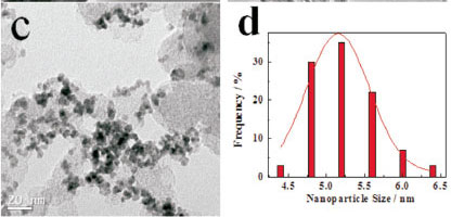
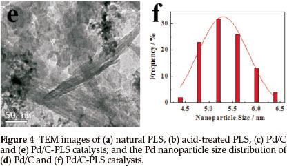
Figure 5 shows the XRD patterns of Pd/C and Pd/C-PLS. It can be observed from the XRD patterns that there are four characteristic peaks of face-centred cubic crystalline Pd, corresponding to (111), (200), (220) and (311) facets, respectively.26 The diffraction peak around 24 ° is the characteristic peak of amorphous Vulcan XC-72 carbon support.27 In the XRD pattern of Pd/C-PLS, a typical diffraction peak of basal space of PLS framework is hardly observed, which may be overlaid by amorphous carbon. Apart from the effect of carbon on the XRD pattern, the intensity of characteristic diffraction peaks of PLS became indistinct after Pd particles were deposited on its surface, possibly due to the weakening of the crystallization of PLS during the Pd depositing procedure as has been observed elsewhere with electroless Ni plated on PLS.28

To identify different electronic structure of Pd on the surface of C and C-PLS supports, Pd/C and Pd/C-PLS were characterized by XPS. Fig. 6a and Fig. 6b show the XPS spectra of the Pd 3d for Pd/C and Pd/C-PLS catalysts, respectively. The Pd 3d XPS spectra of both catalysts can be fitted into two pairs of overlapping Lorentzian curves. The two pairs of peaks indicate that there are two kinds of valence states for Pd, Pd (0) and Pd2+ in PdO29, on the surface of catalysts. Comparison of binding energies of Pd 3d5/2 and Pd 3d3/2 for Pd/C and Pd/C-PLS is presented in Table 1.

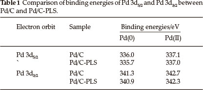
The results show that there is a clear shift of the Pd 3d5/2 and 3d3/2 for Pd/C-PLS to more negative binding energies than that of Pd/C, which may be caused by electro-negative difference of Pd and Si resulting in charge transfer occurring between Pd and Si. The increase of binding energy could affect the interaction strength between Pd nanoparticles and formic acid. The shift of binding energy to the low energy region suggests that slightly decreased interaction strength between formic acid and Pd nanoparticle on the surface of Pd/C-PLS might lead to an increase in the catalytic rate since formic acid would not be strongly chemsorbed on the surface of Pd nanoparticles.
Figure 7 shows the CVs of the Pd/C and Pd/C-PLS catalysts in 0.5 mol L-1 H2SO4 electrolyte between -0.2 and 1.0 V (versus Ag/AgCl) at a scan rate of 50 mV s-1. Both catalysts exhibit the characteristic features of hydrogen adsoption/desorption peaks in low potential region, oxygen adsorption/desorption in high potential region and a flat double layer between them. It can be observed in Fig. 7 that the currents for hydrogen adsorption/ desorption and oxygen adsorption/desorption for Pd/C-PLS are almost same as that of Pd/C. Moreover, there is a clear shift of oxygen reduction peak to the cathodic section, which implies that it is easier to desorb OHads or Oads on the surface of Pd/C-PLS. A similar phenomenon has been also observed in the case of Pt catalyst.30
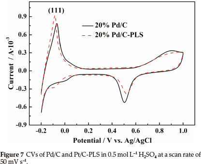
The electrochemical active surface area AEL of different Pd catalyst can be calculated according to Eq. (1)31:

where QH (cm-2) is the average integrated charge of hydrogen adsorption/desorption peak area, [Pd] (cm-2) is Pd loading on the electrode, and 2.1 is the charge (C m-2) required to oxidize a monolayer of hydrogen on the Pd surface. The Ael of an electro-catalyst not only provides important information regarding the number of electrochemically active sites on a mass basis of the precious metal, but also is a crucial parameter to compare different electrocatalytic supports.32 The estimated Ael of Pd/C-PLS and Pd/C are 81 m2 g-1Pd and 83 m2 g-1Pd, respectively. The AEL of Pd/C-PLS is close of that of Pd/C. It should be noted that the estimated AEL is not entirely accurate because H is adsorbed not only on the surface of Pd nanoparticles, but also into the crystal structure. However, these AEL results could give us a qualitative judgment.
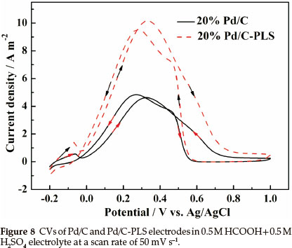
Figure 8 shows the CVs of the Pd/C and Pd/C-PLS in 0.5 mol L-1 H2SO4 + 0.5 mol L-1 HCOOH at a scan rate of 50 mV s-1. It clearly shows that the onset potential of Pd/C-PLS is lower than that of Pd/C. Meanwhile, the peak current density of Pd/C-PLS reaches 10.2 A m-2 during positive potential scanning process which is 2.2 times higher than that of Pd/C catalyst (4.6 A m-2), indicating that the activity towards formic acid electrooxidation for Pd/C-PLS catalyst is much better than Pd/C catalysts.
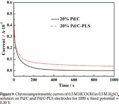
Chronoamperometric curves (Fig. 9) of formic acid oxidation in 0.5 mol L-1 HCOOH in 0.5 mol L-1 MH2SO4 solution at 0.30 V were used to evaluate Pd/C and Pd/C-PLS. Continuous formic acid oxidation occurs on the surface of electrocatalyst when the potential is fixed at 0.30 V Tenacious reaction intermediates such as COad would form and accumulate on the surface of electrocatalysts, which will result in a decay of catalytic activity due to the strong chemisorption of CO.33 In Fig. 9 the decreasing rate of current density with time for Pd/C-PLS is much slower than that of Pd/C, which demonstrates that Pd/C-PLS has better anti-poisoning ability. As expected, the initial current density of Pd/C-PLS is much higher than that of Pd/C.
Here, the so-called 'dual pathway mechanism'34 is used to explain the enhanced catalytic activity of Pd/C-PLS. The first reaction pathway, i.e. HCOOH COad+H2O, forms absorbed carbon monoxide as a reaction intermediate during the dehydration of formic acid step. Pd acts as the main catalyst for the dehydrogenation of formic acid during the oxidation reaction, and oxygen-containing species (OHads) could be provided by SiO2 in PLS. These oxygen-containing species will promote the oxidation of CO-like species on the Pd surface to release the active sites for further oxidation of formic acid, which results in better catalytic activity and anti-poisoning ability.
4. Conclusions
This work proves that introducing the porous SiO2-based PLS into the conventional carbon support can form a nanocomposite support with high stability and electrochemical performance. The results of XRD, BET and TEM showed that the structure of PLS remains intact after acid treatment. Electrochemical results proved that addition of PLS in a conventional carbon support can improve the electrochemical performance. The presence of PLS in carbon support can provide oxygen-containing species, which may react with CO-like species chemisorbed on the surface of Pd nanoparticles, resulting in better anti-poisoning ability. Compared with Pd/C, Pd/C-PLS exhibits higher electrocatalytic activity and better durability for electrooxidation of formic acid, which offers great potential for extensive usage of PLS as support for electrocatalysts.
Acknowledgements
We are most grateful to the National Natural Science Foundation of China (21163018), the National Science Foundation for Post-doctoral Scientists of China (20110490847), Guangdong Key Lab for Fuel Cell Technology and the South African National Research Foundation (SUR 2008060900021) for financially supporting this work.
References
1 C. Rice, S. Ha, R. Masel and A. Wieckowski, J. Power Sources, 2003, 115, 229-235. [ Links ]
2 Y.W. Rhee, S. Ha, C. Rice and R.I. Masel, J. Power Sources, 2003, 117, 35-38. [ Links ]
3 Y. Zhu, Y. Kang, Z. Zou, Q. Zhou, J. Zheng, B. Xia and H. Yang, Electrochem. Commun, 2008, 10, 802-805. [ Links ]
4 Z. Bai, L. Yang, L.Li, J. Lv, K. Wang and J. Zhang, J. Phys. Chem. C, 2009, 113, 10568-10573. [ Links ]
5 R. Chetty, S. Kundu, W. Xia, M. Bron, W. Schuhmann, V. Chirila, W. Brandl, T. Reinecke and M. Muhler, Electrochim. Acta, 2009, 54, 4208-4215. [ Links ]
6 R. Imran Jafri, N. Rajalakshmi and S. Ramaprabhu, J. Power Sources 2010, 195, 8080-8083. [ Links ]
7 Y.H. Pai, J.H. Ke, C.C. Chou, J.J. Lin, J.M. Zen and F.S. Shieu, J. Power Sources, 2006, 163, 398-402. [ Links ]
8 B. Choi, H. Yoon, I.S. Park, J. Jang and Y.E. Sung, Carbon, 2007, 45, 2496-2501. [ Links ]
9 Y. Chen, J. Wang, X. Meng, Y. Zhong, R. Li, X. Sun, S. Ye and S. Knights, Int. J. Hydrogen Energy, 2011, 36, 11085-11092. [ Links ]
10 R. Andrews, D. Jacques, D. Qian and T. Rantell, Acc. Chem. Res., 2002, 35, 1008-1017. [ Links ]
11 E. Antolini, Appl. Catal. B., 2009, 88, 1-24. [ Links ]
12 B. Fang,J.H. Kim, M.Kim and J.S. Yu, Chem. Mater., 2009, 21, 789-796. [ Links ]
13 J. Jia, R. Wang, H. Wang, S. Ji, J. Key, V. Linkov, K. Shi and Z. Lei, Catal. Commun., 2011, 16, 60-63. [ Links ]
14 R. Wang, X. Li, H. Li, Q. Wang, H. Wang, W. Wang, J. Kang, Y. Chang and Z. Lei, Int. J. Hydrogen Energy, 2011, 36 5775-5781. [ Links ]
15 J.N. Tiwari, F.M. Pan, R.N. Tiwari and S.K. Nandi, Chem. Commun., 2008, 48, 6516-6518. [ Links ]
16 B. Seger, A. Kongkanand, K. Vinodgopal and P.V Kamat,J. Electroanal. Chem., 2008, 621, 198-204. [ Links ]
17 M. Kara, H. Yuzer, E. Sabah and M.S. Celike, Water Res., 2003, 37, 224-232. [ Links ]
18 M.A. Aramendia, V Borau, G. Jimenez, J.M. Marinas, A. Porras, F.J. Urbano and L. Villar, J. Mol. Catal, 1994, 94, 131-147. [ Links ]
19 J. Zhu, A.B. Morgan, F.J. Lamelas and C.A. Wilkie, Chem. Mater., 2001, 13, 3774-3780. [ Links ]
20 G. Sandí, R.E. Winans, S. Seifert and K.A. Garrado, Chem. Mater., 2002, 14, 739-742. [ Links ]
21 D.M. Araújo Melo, J.A.C. Ruiz, M.A.F. Melo, E.V Sobrinho and A.E. Martinelli, J. Alloys Compd., 2002, 344, 352-355. [ Links ]
22 R. Wang, J. Jia, H. Li, X. Li, H. Wang, Y. Chang, J. Kang and Z. Lei, Electrochim. Acta, 2011, 56, 4526-4531. [ Links ]
23 N.W. Ockwig, J.A. Greathous, J.S. Durkin, R.T. Cygan, L.L. Daemen and T.M. Nenoff, J. Am. Chem. Soc., 2009, 131, 8155-8162. [ Links ]
24 D.K. Smith, M.E. Mrose, L.G. Berry and P. Bayliss, Selected Power Diffraction Data for Minerals, Joint Committee on Powder Diffraction Standards, USA, 1974. [ Links ]
25 N.F. Srasra, E. Srasra, Surf. Eng. Appl. Elect., 2008, 44, 43-49. [ Links ]
26 Y. Zhao, L. Zhan, J. Tian, S. Nie and Z. Ning, Electrochim. Acta, 2011, 56, 1967-1972. [ Links ]
27 X. Zhang, H. Wang, J. Key, V. Linkov, S. Ji, X. Wang, R. Fang and Z. Lei, J. Electrochem. Soc., 2012, 159, B1-B7. [ Links ]
28 S. Zhou,L. WangandS. Shen,Appl. Surf. Sci., 2011, 257, 10211-10217. [ Links ]
29 H. Meng, F. Xie, J. Chen and P. Shen, J. Mater. Chem., 2011, 21, 11352-11358. [ Links ]
30 X. Li, X. Qiu, H. Yuan, L. Chen and W. Zhu, J. Power Sources, 2008, 184, 353-360. [ Links ]
31 H. Wang, X. Zhang, R. Wang, S. Ji, W. Wang, Q. Wang and Z. Lei, J. Power Sources, 2011, 196, 8000-8003. [ Links ]
32 D.H. Lim, W.D. Lee, D.H. Choi, D.R. Park and H.I. Lee, J. Power Sources, 2008, 185, 159-165. [ Links ]
33 D. Guo, X. Qiu, L. Chen and W. Zhu, Carbon, 2009, 47, 1680-1685. [ Links ]
34 Y. Zhou, J. Liu, J. Ye, Z. Zou, J. Ye, J. Gu, T. Yu and A. Yang, Electrochim. Acta, 2010, 55, 5024-5027. [ Links ]
Received 10 December 2012
Revised 14 February 2013
Accepted 22 March 2013
* To whom correspondence should be addressed. E-mail: wrf38745779@126.com
** sji@uwc.ac.za

