


Serviços Personalizados
Artigo
 Inglês (pdf)
 Artigo em XML
 Referências do artigo
Indicadores

Links relacionados
-
 Citado por Google
 -
 Similares em Google
Compartilhar

 Permalink
South African Journal of Chemistry
versão On-line ISSN 1996-840X
versão impressa ISSN 0379-4350
S.Afr.j.chem. (Online) vol.66 Durban Ago. 2013
RESEARCH ARTICLE
Amorphous Pt@PdCu/CNT catalyst for methanol electrooxidation
Hui WangI; Shan JiII, *; Wei WangI; Rongfang WangII, *
IKey Laboratory of Eco-Environment-Related Polymer Materials, Ministry of Education of China, Key Laboratory of Gansu Polymer Materials, College of Chemistry and Chemical Engineering, Northwest Normal University, Lanzhou 730070, China
IISouth African Institute for Advanced Materials Chemistry, University of the Western Cape, Cape Town 7535, South Africa
ABSTRACT
A multi-walled carbon nanotube-supported, Pt decorated nano-sized amorphous PdCu alloy cores (denoted as Pt@PdCu/CNT) catalyst with lower Pt loading is synthesized via a galvanic displacement reaction. The structure is examined using X-ray diffraction (XRD) and transmission electron microscopy (TEM). The electrochemical activity of the Pt@PdCu/CNT catalyst is tested by cyclic voltammogrametry (CV) and compared to that of PtRu/CNT catalysts. The results show that amorphous Pt@PdCu/CNT catalyst exhibits better electro-catalytic performances for methanol oxidation than its crystalline counterpart.
Keywords: Amorphous, decorated structured, Pt@PdCu/CNT, electrocatalyst, methanol oxidation.
1. Introduction
Direct methanol fuel cells, which can directly convert chemical energy to electricity, are in high demand for portable electrical device due to its high energy density, low emission, no toxicity, ease of processing and low operating temperature1-3. Pt-based catalysts are the most common attractive electrocatalysts, which dominate the application in cathode and anode in proton exchange membrane fuel cells1. Currently, the high cost, unsatisfactory activity, and low durability of Pt-based catalysts are the major challenges that hinder fuel cell commercialization. With regards to these challenges, the high cost of Pt metal has been identified as a major problem. Thus, significant efforts have been made, worldwide, to produce a low cost and high efficient Pt-based electrocatalysts. These efforts mainly focus on exploring non-noble catalysts and developing new nano-structured Pt-based materials.
Developing core-shell structure and introducing low cost metals into Pt-based electrocatalysts are efficient ways of reducing the cost of electrocatalysts. It is well documented that the core-shell structures of metallic nano-alloys usually exhibit superior activity in heterogeneous catalysis due to the interaction between the metals4-7. However, the utilization rate of Pt in these catalysts is still not high enough to meet the requirements of electro-catalysts for DMFC commercialization.
Nowadays, developing new structured Pt-based electro-catalysts for PEM fuel cells has became an active research topic owing to their unique properties, and their potential to further reduce Pt loading8-10. Among these new Pt-based electro-catalysts, amorphous metal catalysts with long-range disordering and short-range ordering have attracted a lot of attention due to their unique isotropic structure. Compared with their crystalline counterparts, amorphous catalysts have a higher concentration of co-ordinately unsaturated sites on their surface11-13. Amorphous Ni-based alloys exhibit excellent catalytic activity and selectivity equivalent in various hydrogenation processes14-17. There are some reports on employing amorphous metal as the core or shell in core-shell structured nanoparticles18,19. For example, carbon-supported Pt@Fe core-shell catalysts with Fe cores in different crystal states were synthesized, and, in contrast to its crystallized counterparts, the iron in the amorphous state exerts a distinct and powerful ability as a core for the Pt@Fe nano-particles. However, to date, far less research has focused on amorphous electro-catalysts in methanol oxidation20-22. Promising results were obtained by the Barranco's group who observed the enhanced catalytic activity of Pt alloy amorphous electro-catalysts in methanol oxidation due to a complex function of electronic, geometric, and synergistic effects23-27. However, the amorphous Pt-contenting catalysts were prepared via a mechanical alloying technique and the resulting alloys were micro particles.
In the literature, there is no work reported using nano-sized amorphous metal as a core and shell for electro-catalyst in methanol oxidation. In this study, a two-step reduction method was developed to prepare a multi-walled carbon nanotube-supported, Pt decorated, nano sized, amorphous PdCu alloy cores (denoted as Pt@PdCu/CNT) catalyst, which was evaluated by methanol oxidation. The morphology and electro-catalytic behaviour of synthesized c were investigated.
2. Experimental
2.1. Catalysts Synthesis
Palladium chloride (PdCl2) (26 mg), copper(II) chloride dihydrate (25 mg) and sodium citrate (195 mg) were dissolved in ethylene glycol (EG) and stirred for 0.5 h. Pre-treated, multi-walled, carbon nanotubes (100 mg) were added to the mixture with stirring. The pH of the solution was adjusted to ~10 by 5 wt% KOH/EG solution. The mixture was then placed into a Teflon-lined autoclave and heated to 160 °C for 6 h, filtered, washed with deionized water five times and dried in air at 70 °C. The obtained PdCu/C powders (50 mg) and H2PtCl6 (5.3 mg) were introduced into a flask with 20 mL water and stirred for 4 h at 80 °C. The reduction of Pt is most likely to occur on the surface of PdCu particles because of the following reasons: firstly, new Pt nuclei are not energetically favourable in the solution phase in the Finke-Watzky mechanism28; and secondly, PdCu nanoparticles have a large number of energetically unsaturated atoms29. The resulting powder was washed with deionized water until no chloride anion was found in the filtrate; followed by drying in air at 70 °C. The Pt@PdCu/C catalyst (20 % metal loaded) was obtained. For comparisons, the PtRu/CNT (atomic ratio of Pt:Ru = 1:1) was prepared via the same reduction procedure.
2.2. Catalyst Characterizations
The catalysts were characterized by recording their XRD patterns on a Shimadzu XD-3A (Japan), using filtered CuKα radiation. All X-Ray Diffraction patterns were analyzed using Jade 7.5 of Material Data, Inc. (MDI); peak profiles of individual reflections were obtained by a nonlinear least-square fit of the Cu Kα corrected data. The transmission electron microscope (TEM) measurements were carried out on a JEM-2010 Electron Microscope (Japan); the acceleration voltage was 200 kV. The average chemical compositions for PdCu/CNT and Pt@PdCu/ CNT catalysts were determined by the EDX technique coupled to TEM.
2.3. Preparation of Electrodes
The electrochemically measurements of catalysts were performed by using an electrochemical work-station (CHI604). A common three-electrode electrochemical cell was used for the measurements. The counter and reference electrode were a platinum wire and an Ag/AgCl (KCl 3 M) electrode, respectively. The working electrode was a glassy carbon disk (5 mm in diameter). The thin-film electrode was prepared as follows: 5 mg of catalyst was dispersed ultrasonically in 1 mL Nafion/ethanol (0.25 % Nafion) for 15 min. 8µL of the dispersion was transferred onto the glassy carbon disk using a pipette, and then dried in the air to form catalyst layer on it. All electrochemical tests were carried out at ambient temperature.
3. Results and Discussions
Figure 1 illustrates the XRD patterns of the PdCu/CNT and Pt@PdCu/CNT catalysts. A broad peak in the range 2θ = 37° to 45 ° clearly appeared on the XRD pattern of PdCu/CNT and Pt@PdCu/CNT and is attributed to the merger of the peaks of (111) and (200) planes. Except for the broad peak, there were no other peaks observed in both XRD patterns. Compared with values of 2θ of Pd fcc (which is show as a black line at the bottom of Fig. 1), the broad peak in the XRD pattern of PdCu/CNT shifts to higher 2θ value with relatively smaller lattice parameter, indicating that copper atoms were inserted into the palladium lattice. The lack of the peaks corresponding to the fcc (220), (311) and (222) planes of Pd and the shift of the board peak suggest that amorphous PdCu alloy were formed in both PdCu/CNT and Pt@PdCu/CNT catalysts30-32. In the XRD pattern of Pt@PdCu/CNT, no peaks related to crystalline Pt was observed which means an amorphous Pt structure was formed on the surface of amorphous PdCu alloy33. Compared with XRD pattern of PdCu/CNT, it also is found that the board peak in the XRD of Pt@PdCu/CNT shifts to low 2θ value, which indicated that Pt atoms are inserted into the PdCu lattice because the diameter ofPt atom is bigger than these of Pd and Cu atoms.
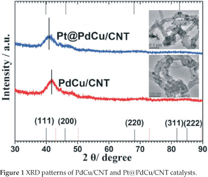
Typical TEM images ofPdCu/CNT and Pt@PdCu/CNT samples are also shown in Fig. 1. It can be seen that the PdCu and Pt@PdCu particles are dispersed onto the carbon nanotubes with high dispersion. The size of distribution of PdCu and Pt@PdCu particles is narrow, mainly in the range of 9~10 nm with the average particle size of ca. 9.7 nm for both catalysts.
Figure 2a and Fig. 2b show the representative high-resolution transition electron microscopy (HRTEM) images of PdCu and Pt@PdCu particles dispersed on CNT. The dark spots, without obvious crystalline pattern, are presented in both HRTEM images. It can be well distinguished from the graphitic carbon background, where there are the ordered graphitic layers with a typical configuration of CNT34. The lack of crystalline pattern in the particle image further proves that amorphous PdCu and Pt@PdCu alloy nano-particles were formed on the surface of the CNTs. The composition of PdCu/CNT and Pt@PdCu/CNT electro-catalysts determined by EDX analysis are shown in Fig. 2c and Fig. 2d. Atomic ratios of Pd:Cu and Pt:Pd:Cu are 1:1 and 1:2.8:3.3 for PdCu/CNT and Pt@PdCu/CNT, respectively, which are close to the ratios of Pt, Pd and Cu precursors. These ratios show that most of the Pt particles are formed on the surface of the PdCu particles and not in the solution.
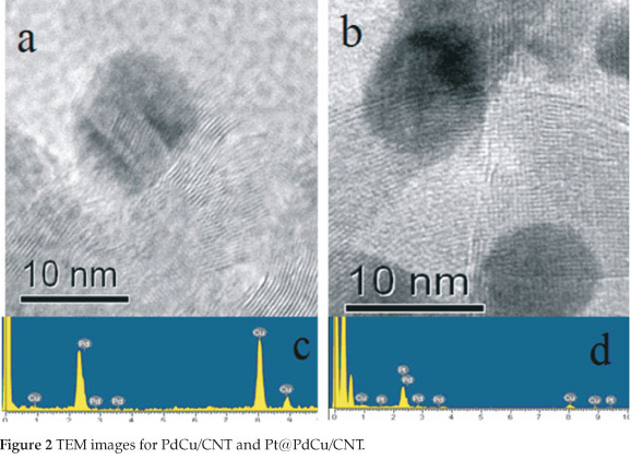
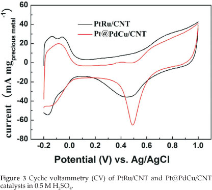
Figure 3 depicts the cyclic voltamogram (CV) of PtRu/CNT and Pt@PdCu /CNT catalysts in 0.5 M H2SO4 between -0.2 and +1.0 V (vs. Ag/AgCl) at a scan rate of 50 mV s-1 at room temperature. The characteristic features of Pt, i.e. hydrogen adsorption/desorption peaks, oxide formation/stripping wave/peak, and a flat double layer region in between, are presented in the CVs for both catalysts. The onset potentials for the oxide reduction in the negative-going sweep are slightly shifted to more positive potential for Pt@PdCu/CNT catalyst as compared to PtRu/CNT. This shift indicates that Pt@PdCu/CNT inhibits chemisorption of the oxygenated species, such as chemisorbed OHad on the Pt sites at high potential (above 0.8 V). The electrochemically surface area (ECSA) of catalysts can be calculated by using the integrated charge in the hydrogen adsorption region according to the equation: ECSA (m2 gPt-1) = QH/210xWPt), where QH stands for the total charge (C) during hydrogen adsorption on the Pt surface, 210 is the charge (C) corresponding to the adsorption of a monolayer of hydrogen on a polycrystal-line Pt surface. WPt (g cm-2) is the Pt loading on the electrode. Based on the Pt mass, the ECSA is 65.61 m2 g-1 Pt for PtRu/CNT and 139.4 m2 g-1 Pt for Pt@PdCu/CNT. The ECSA of Pt@PdCu/CNT is 2.12 times more than that of the PtRu/CNT catalysts. The high ECSA of Pt@PdCu/CNT catalyst implies that the utilization rate of Pt for the Pt@PdCu/CNT is much higher than the PtRu/CNT catalysts.
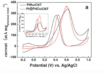
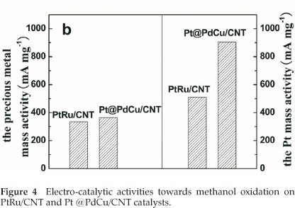
The electro-catalytic activity towards methanol oxidation on the surfaces of PtRu/CNT and Pt@PdCu/CNT catalysts were analyzed by CV in 0.5 M H2SO4 and 0.5 M CH3OH, which are normalized by both the precious mass (Pt, Pd and Ru) and the Pt mass (mass activity), respectively, and presented in Fig. 4. From Fig. 4a, it is clearly shown that the mass activity (i.e. the forward anodic peak, If) of Pt@PdCu/CNT catalysts is higher than that of PtRu/CNT catalysts. The values presented in Fig. 4b are comparable or higher than the results reported by our group35,36. The CV results clearly exhibit that the amorphous Pt@PdCu/CNT catalyst has a better electro-catalytic performance than the crystalline PtRu/CNT catalyst in terms of both precious metal and Pt mass activity. As shown in Fig. 4b, the mass activities based on the precious mass and Pt mass for Pt@PdCu/CNT catalyst towards methanol oxidation is about 4.48 times and 2.70 times more than those of PtRu/CNT catalysts, respectively.
In our previous studies, carbon support PdCu (PdCu/C) and Pt@PdCu (Pt@PdCu/C) nanoparticle35,36 were also prepared via the same procedure used in this study. However, the PdCu and Pt@PdCu nanoparticles deposited on the carbon support were crystalline alloy. In this study, the HREM and XRD results clearly show that the PdCu and PdCu@Pt nanoparticles supported on CNT are amorphous. These results show that the morphology of support materials play an important role on the formation of nanoparticles deposited on it during the reduction of precursors. A recent review on the theory and application of alloy clusters and nanoparticles summarized the work related to Pd-Cu alloy nanoparticles, which indicated that the structure of a Pd-Cu alloy was based on a complex balance between surface segregation by copper and subsurface mixing with palladium37. The balance is related to the size, composition and shape of the nanoparticles as well as the interaction with the support. Compared with the procedure of preparing crystalline PdCu/C, amorphous PdCu alloy nanoparticles formed on the surface CNTs even the reduction procedures were exactly the same, which indicates that different support materials can result in different morphologies of the nanoparticles deposited on it. This study also shows that the Pt nanoparticles formed on the surface of amorphous PdCu core are amorphous. However, our previous study showed that the Pt nanoparticles formed on the crystalline PdCu cores were fcc crystalline structure. These results further prove that Pt growth kinetics is associated with the PdCu nucleation28,29.
As shown in Fig. 4, the Pt@PdCu/CNT catalyst exhibits a marked improvement in activity for methanol oxidation based on Pt mass. This improvement is attributed to a combined structure of amorphous core and Pt decorated surface of Pt@PdCu nanoparticles. On one hand, amorphous structure of Pt@PdCu nanoparticles could offer more active sites for methanol oxidation, which is demonstrated by the larger ECSA. On the other hand, since Pt atoms were only decorated the surface of the PdCu core, it can maximize the utilization of Pt in the catalysts. Therefore, the Pt decorated amorphous PdCu core catalyst exhibits better electro-catalytic performance than its crystalline counterpart.
4. Conclusions
Amorphous Pt@PdCu electro-catalyst supported on multi-walled carbon nanotubes were successfully synthesized by a simple two-step route. XRD, TEM and SEM confirm the amorphous and decorated structure. The ECSA of the Pt@PdCu/ CNT catalyst is 2.12 times more than that of the PtRu/CNT catalyst. Based on the precious metal mass and Pt mass, the mass activity of Pt@PdCu /CNT catalyst, towards methanol oxidation, is about 4.48 times and 2.70 times more than those of PtRu/CNT catalysts. This enhancement results from the combined structure of amorphous core and Pt decorated surface of the Pt@PdCu/CNT catalyst. This study shows that developing amorphous nano-structured materials will be a promising approach for further improving the electro-catalytic performance for Pt-based fuel cell catalysts.
Acknowledgement
The authors would like to thank the National Natural Science Foundation of China (21163018), the National Science Foundation for Post-doctoral Scientists of China (20110490847), Guangdong Key Lab for Fuel Cell Technology and the South African NRF (SUR 2008060900021) for financially supporting this work.
References
1 Y. Wang, D.P. Wilkinson and J. Zhang, Chem. Rev., 2011,111, 7625. [ Links ]
2 S. Liao, K. Holmes, H. Tsaprailis and V Birss, J. Am. Chem. Soc., 2006, 128, 3504. [ Links ]
3 W. Wang, R. Wang, H. Wang, S. Ji, J. Key, X. Li and Z. Lei, J. Power Sources, 2011, 196, 9346. [ Links ]
4 J. Luo, L. Wang, D. Mott, P.N. Njoki, Y. Lin, T. He, Z. Xu, B.N. Wanjala, I.S. Lim and C. Zhong, Adv. Mater., 2008, 20, 4342. [ Links ]
5 H.L. Jiang, T. Akita, T. Ishida, M. Haruta, Q. Xu, H.L. Jiang, T. Akita, T. Ishida, M. Haruta and Q. Xu, J. Am. Chem. Soc., 2011, 133, 1304. [ Links ]
6 D. Wang and Y. Li, Adv. Mater., 2011, 23, 1044. [ Links ]
7 X. Zhang, H. Wang, J. key, V. Linkov, S. Ji, X. Wang, Z. Lei and R. Wang, J. Electrochem. Soc., 2012, 159, B270. [ Links ]
8 H.L. Jiang, T. Akita, T. Ishida, M. Haruta and Q. Xu, J. Am. Chem. Soc., 2011, 133, 1304. [ Links ]
9 X.B. Zhang, J.M. Yan, S. Han, H. Shioyama and Q. Xu, J. Am. Chem. Soc., 2009, 131, 2778. [ Links ]
10 J. BarrancoandA. R. Pierna, J. New Mat. Electrochem. Systems, 2009, 12, 69. [ Links ]
11 A. Molnar, G.V. Smith and M. Bartok, Adv. Catal., 1989, 36, 329. [ Links ]
12 J.F. Deng, H.X. Li and W.J. Wang, Catal. Today, 1999, 51, 113. [ Links ]
13 V. Kesavan, D. Dhar, Y, Koltypin, N. Perkas, O. Palchik, A. Gedanken and S. Chandrasekaran, Pure Appl. Chem., 2001, 73, 85. [ Links ]
14 Y. Pei, J.Q. Wang, Q. Fu, P.J. Guo, M.H. Qiao, S.R. Yan and K.N. Fan, New J. Chem., 2005, 29, 992. [ Links ]
15 W.Y. Wang, Y.Q. Yang, H.A. Luo, T. Hu and W.Y. Liu, Reac. Kinet. Mech. Cat., 2011, 102, 207. [ Links ]
16 L.F. Chen and Y.W. Chen, Ind. Eng. Chem. Res., 2006, 45, 8866. [ Links ]
17 W.L. Dai,H.X. Li, Y. Cao,M.H. Qiao,K.N. FanandJ.F. Deng,Langmuir, 2002, 18, 9605. [ Links ]
18 X.B. Zhang, J.M. Yan, S. Han, H. Shioyama and Q. Xu, J. Am. Chem. Soc., 2009, 131, 2778. [ Links ]
19 H. wang, X.T. Zhang, R.F. Wang, S. Ji, W. Wang, Q.Z. Wang and Z.Q. Lei, J. Power Sources, 2011, 196, 8000. [ Links ]
20 S.G. Sun, J. Lipkowski and Z. Altounian, J. Electrochem. Soc., 1990, 137, 2443. [ Links ]
21 K. Seto, J. Noël, J. Lipkowski, Z. Altounian and R. Reeves, J. Electrochem. Soc., 1989, 136, 1910. [ Links ]
22 A. Aramata and M. Masuda, J. Electrochem. Soc., 1991, 138, 1949. [ Links ]
23 J. Barranco and A.R. Pierna, J. Non-Cryst. Solids, 2007, 353, 851. [ Links ]
24 J. Barranco and A.R. Pierna, J. Non-Cryst. Solids, 2008, 354, 5153. [ Links ]
25 J. BarrancoandA. R. Pierna, J. New Mat. Electrochem. Systems, 2009, 12, 69. [ Links ]
26 J. BarrancoandA. R. Pierna, J. New Mat. Electrochem. Systems, 2009, 12, 81. [ Links ]
27 J. Barranco and A.R. Pierna, J. Power Sources, 2007, 169, 71. [ Links ]
28 M.A.Watzky and R.G. Finke, J. Am. Chem. Soc., 1997, 119, 10382. [ Links ]
29 H. Gao, S. Liao, J. Zeng, Y. Xie and D. Dang, Electrochim. Acta, 2011, 56, 2024. [ Links ]
30 K. Mondal, B.S. Murty and U.K. Chatterjee, Corrosion Science, 2005, 47, 2619. [ Links ]
31 C. Li, S. Ranganathan and A. Ionue, Acta Mater., 2001, 49, 1903. [ Links ]
32 K.A.Guy, H.P.Xu, J.C. Yang, C.J. Werthand J.R. Shapley, J. Phys. Chem. C, 2009, 113, 8177. [ Links ]
33 Y.B. Sun, L. Zhuang, J.T. Lu, X.L. Hong and P.F. Liu, J. Am. Chem. Soc., 2007, 129, 15465. [ Links ]
34 S.H. Jeong, H.Y. Hwang, S.K. Hwang and K.H. Lee, Carbon, 2004, 42, 2073. [ Links ]
35 R.F. Wang, Z. Zhang, H. Wang and Z.Q. Lei, Electrochem. Commun., 2009, 11, 1089. [ Links ]
36 H. Wang, R.F. Wang, H. Li, Q.F. Wang, J. Kang and Z.Q. Lei, Int. J. Hydrogen Energy, 2011, 36, 839. [ Links ]
37 R. Ferrando, J. Jellinekand R.L. Johnston, Chem. Rev., 2008, 108, 845. [ Links ]
Received 29 July 2012
Revised 9 October 2012
Accepted 19 November 2012
* Authors for correspondence. E-mail: sji@uwc.ac.za / wrf38745779@126.com

