


Serviços Personalizados
Artigo
 Inglês (pdf)
 Artigo em XML
 Referências do artigo
Indicadores

Links relacionados
-
 Citado por Google
 -
 Similares em Google
Compartilhar

 Permalink
South African Journal of Science
versão On-line ISSN 1996-7489
versão impressa ISSN 0038-2353
S. Afr. j. sci. vol.120 no.3-4 Pretoria Mar./Abr. 2024
http://dx.doi.org/10.17159/sajs.2024/16026
RESEARCH ARTICLE
Development of unsupported IrO2 nano-catalysts for polymer electrolyte membrane water electrolyser applications
Simoné Kareis; Cecil Felix; Sivakumar Pasupathi
South African Institute for Advanced Materials Chemistry (SAIAMC), University of the Western Cape, Cape Town, South Africa
ABSTRACT
IrO2 is a current state-of-the-art catalyst for polymer electrolyte membrane water electrolyser (PEMWE) applications due to its high stability during the oxygen evolution reaction (OER). However, its activity needs to be significantly improved to justify the use of such a high-cost material. In this study, the activity of the IrO2 catalyst was improved by optimising and comparing two synthesis methods: the modified Adams fusion method (MAFM) and the molten salt method (MSM). Optimum OER performances of the IrO2 catalysts synthesised with the two synthesis methods were obtained at different temperatures. For the MAFM, a synthesis temperature of 350 °C produced the IrO2 catalyst with an overpotential of 279 mV and the highest OER stability of ~82 h at 10 mAcm-2. However, for the MSM, the lowest overpotential of 271 mV was observed for IrO2 synthesised at 350 °C, while the highest stability of ~75 h was obtained for the IrO2 synthesised at 500 °C.
SIGNIFICANCE:
IrO2 is still currently a state-of-the-art catalyst in PEMWE due to its high stability in the highly acidic and oxidising conditions of the OER. High-performance IrO2 catalysts were successfully produced via the MAFM and MSM. Both the MAFM and MSM are simple and easily scalable for high-volume production of metal oxide catalysts. This study showed that the physical/structural properties of the IrO2 catalysts can be tailored through synthesis methods and synthesis conditions to improve their OER performance.
Keywords: iridium oxide, oxygen evolution reaction, modified Adams fusion method, polymer electrolyte membrane water electrolyser, molten salt method
Introduction
The polymer electrolyte membrane water electrolyser (PEMWE) is an important technology to produce hydrogen (H2) from renewable energy sources, i.e. green H2, due to its adaptability to the intermittent energy profiles of renewable energy sources like solar and wind power. However, the high costs associated with PEMWE components have remained a major challenge for the commercialisation of the technology. The high cost of the catalyst is of particular importance as it accounts for about 25% of the total catalyst-coated membrane cost. Furthermore, the catalyst-coated membrane shares about 24% of the total PEMWE stack cost.1 The oxygen evolution reaction (OER) is a four-electron process dominated by sluggish electrode kinetics, leading to high overpotentials.2 Therefore, the anodic catalyst in the PEMWE needs to be especially active and stable under the acidic OER environment to reduce the high overpotential. Expensive precious metals and their respective oxides are still known to be the most active and stable towards the OER although alternative non-precious metal materials are being investigated.3 While high activities are obtained from non-precious metal catalysts, major challenges such as long-term stability need to be addressed before employing these materials as electrodes for large-scale, practical applications.4 Metal oxides based on Ir and Ru are considered state-of-the-art catalysts for the OER because of their high activity and stability.2 The IrO2 catalyst has low overpotential, maintains high stability in acidic media, is corrosion resistant, and has a high selectivity towards oxygen evolution.5 Wáng et al.6 summarised the ex-situ OER performances of various materials that incorporated either Ir or Ru into its matrix. A second-best performance was obtained with Ir0.06Co2.94O4 on an Au electrode exhibiting an overpotential of 250 mV and a stability of 200 h at 10 mVcm-2. However, it should be noted that the best performance obtained on a glassy carbon electrode (GCE) (out of 24 studies) was for a/c-RuO2, which exhibited a 205 mV overpotential and a stability of 60 h at 10 mVcm-2.7 The best performance for a monometallic Ir catalyst on a GCE was for mesoporous Ir nanosheets exhibiting an overpotential of 240 mV and a stability of 8 h at 10 mA/cm2. These findings might suggest that the working electrode type has a significant impact on the measured OER performances.
In this study, the IrO2 catalysts were developed via two methods: a modified Adams fusion method (MAFM) and a molten salt method (MSM). Although IrO2 is a commonly used catalyst in the PEMWE, its OER activity needs to be significantly improved to justify the use of such an expensive material. The OER performance of the catalyst depends critically on its morphology, shape and crystal structure.2,8 Besides optimising the physical properties of IrO2, the synthesis methods need to be cost-effective, easily scalable, green and clean.8 Since the introduction of the Adams fusion method in 1923 by Roger Adams and Ralph Shriner9, the method has been modified and adapted to synthesise various metal oxides including single, binary and ternary metal oxides, supported and unsupported metal oxides as well as adding chemical modifiers to improve the physical properties of the catalysts.4,10-14 Researchers have used various metals, reagent salts and synthesis temperatures to synthesise various metal oxides.15 During the MAFM, the temperature used causes the NaNO3 to melt and react with the Ir precursor. The synthesis temperature is always set to at least above the melting point of NaNO3 i.e., above 308 °C. The MSM is also a simple, cost-effective, easily scalable and eco-friendly method for the synthesis of metal oxide catalysts.8 During the MSM, the metal chloride precursor decomposes on the NaCl/KCl salt bed. The NaCl/KCl salt bed does not chemically react with the Ir precursor but acts as a support for the thermal decomposition of the Ir precursor in air. The synthesis temperature is mostly kept at 650 °C, which is below the melting point of the NaCl/KCl salt mixture.12 Previous studies suggested the MAFM IrO2 catalysts showed improved OER performance compared to MSM IrO2 catalysts.10,16 In this study, the MAFM and MSM were optimised by varying the synthesis temperatures, and the results were directly compared. Moreover, the reaction time of the MSM was reduced to 4 h (typically 12 h) and only NaCl was used as the salt bed.16 The MAFM and MSM were compared by examining the physical and electrochemical properties of the synthesised IrO2 catalysts. The IrO2 catalysts were physically characterised using X-ray diffraction (XRD), high-resolution transmission electron microscopy (HRTEM) and Brunauer-Emmett-Teller (BET) analyses. The IrO2 catalysts' OER performances were evaluated ex-situ via cyclic voltammetry (CV), linear sweep voltammetry (LSV) and chronopotentiometry (CP).
Methods
Electrocatalyst synthesis
Modified Adams fusion method
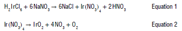
An amount of 0.36 g H2IrCl6 (SA Precious Metals) was dissolved in 10 mL isopropanol (Sigma) and magnetically stirred for 30 min. Thereafter, 3.6 g of finely ground NaNO3 (Alfa Aesar) sample was added to the solution and stirred for an additional 30 min. Excess solvent was evaporated on a hot plate followed by further drying in an oven set to 90 °C, for 30 min. The dried H2IrCl6/NaNO3 mixture was then reacted in a pre-heated furnace for 2 h to produce the IrO2 sample. The furnace temperatures selected for IrO2 synthesis were 350 °C, 500 °C and 650 °C. The obtained IrO2 sample was cooled, rinsed and filtered three times with 500 mL of ultrapure water (Milli Q) to remove the unreacted NaNO3 salt. A 0.1 M AgNO3 solution was used to ensure no chloride was present in the filtrate of the final 500 mL ultrapure water rinse/filter. After filtration, the IrO2 sample was dried in an oven for 4 h at 85 °C and then cooled down overnight inside the oven. A commercial IrO2 (Alfa Aesar) was used for comparison purposes. The samples synthesised using the MAFM are represented as MAFM-350, MAFM-500 and MAFM-650 to denote the different synthesis temperatures. Equations 1 and 2 show the suggested reactions occurring during the MAFM to produce the IrO2 catalyst.17
Molten salt method
An amount of 0.4 g of H2IrCl6 (SA Precious Metals) and 15 g of NaCl (Laborem Lab Supplies) was grounded together for 15 min with a pestle and mortar. The H2IrCl6/NaCl mixture was then transferred to a crucible and reacted in a pre-heated furnace for 4 h. Furnace temperatures selected for IrO2 synthesis were 350 °C, 500 °C and 650 °C. Filtration, rinsing and drying were the same as for the MAFM. The samples synthesised using the MSM are represented as MSM-350, MSM-500 and MSM-650 to denote the different synthesis temperatures. A commercial IrO2 (Alfa Aesar) was used for comparison purposes.
Preparation of the working electrode
A Metrohm rotating disc electrode (RDE) setup fitted with a GCE (0.1963 cm2 working area) was used for the electrochemical analyses. The GCE was cleaned with 0.05 μm alumina paste (Buehler), polished and dried
before use. The catalyst inks were prepared by ultrasonically dispersing 8 mg of the IrO2 catalyst, 50 μL 5 wt% Nafion® solution (Alfa Aesar) and 1950 μL ultrapure water for 20 min. A micropipette was used to drop 30 μL of the IrO2 catalyst ink onto the GCE. The working electrode was covered with a glass beaker and dried for 24 h at ambient conditions. A calculated catalyst loading of 0.45 mg cm2 was obtained.
Physical characterisation
XRD was performed with the Bruker AXS D8 Advance diffractometer using Cu K radiation (x = 1.5406 Â) operating at 40 kV and 40 mA. The IrO2 standard (JCP2 150870) was used for peak allocation. HRTEM was obtained using an FEI/Tecnai T20 operating at 200 kV. BET surface area analyses were performed using the Micromeritics 3 Flex surface characterisation analyser.
Electrochemical characterisation
Ex-situ electrochemical analyses were performed in a three-electrode setup at 25 °C and 1 atm. The Autolab potentiostat PGSTAT302N (Metrohm) was used for all electrochemical analyses. A circulating water bath was used to maintain the temperature of the electrochemical cell. The working electrode (described in 2.2), a 3 M Ag/AgCl reference electrode (Metrohm), a Pt metal sheet (1 cm2 area) counter electrode (Metrohm), which is five times larger than the working electrode and a 0.5 M H2SO4(aq) electrolyte were used. All cell potentials in this work were reported versus the reversible hydrogen electrode (RHE). Potentials were converted from the 3 M Ag/AgCl electrode to the RHE by adding 210 mV to all measured potentials using the measured Pt opencircuit potential in the electrolyte. The current was reported to current density by converting the surface area of the working electrode to 1 cm2 by dividing the current measured with the geometric surface area of the GCE. The electrolyte was purged with N2 for 15 min before performing electrochemical measurements. Electrode activation was performed via CV cycling in the potential window 0 to +1.4 V versus RHE at a potential scan rate of 20 mVs-1 for 50 cycles before conducting any electrochemical characterisations. For LSV and CP analyses, the speed of the RDE was set to 1600 rotations per minute (rpm).
Results and discussion
Physical characterisation
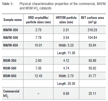
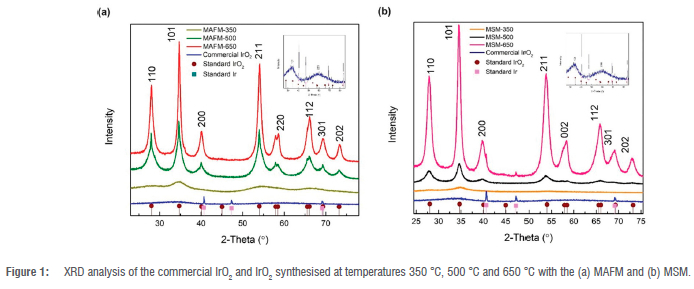
The XRD spectra of the IrO2 synthesised with the MAFM and MSM, compared to the commercial IrO2, are shown in Figure 1. The IrO2 peaks were assigned using the JCP2 standard files for IrO2 (JCP2 150870) and Ir (JCP2 06-0598). In Figure 1a, the sharpening of the peaks with increasing synthesis temperatures (350-650 °C) shows the phase transition from an amorphous to crystalline IrO2. The increased crystallinity for IrO2 can be seen by the sharpening of the diffraction peaks, which are known to produce larger crystallite/particle sizes. This is common for the MAFM because NaNO3 is used as the oxidising agent.18 Sample MAFM-350 was in the amorphous phase, characterised by broad peaks,19 and is known to consist of smaller particle sizes, ~2.73 nm. The (110) and (101) facets, which are important stable facets for IrO2, were present in samples MAFM-500 and MAFM-650, while only facet (101) was present in MAFM-350. Furthermore, the (211) facet at Bragg angle ~69° was present for MAFM-500 and MAFM-650 due to increased crystallisation. The characteristic rutile tetragonal IrO2 peaks are noticeable for samples synthesised at 500 °C and 650 °C. A similar observation of increased crystallinity with increasing synthesis temperatures, 500-650 °C, was reported by Arico et al.20 The average crystallite/particle sizes are determined at the (101) facet using the Scherrer formula as shown in Equation 3.21

where d = average crystallite/particle size, 0.9 = shape factor, λ= x-ray wavelength, p = peak width at half peak height and 9 = Bragg angle. The (101) facet is preferred since it is a closed-packed Ir atom plane.22
MAFM-500 and MAFM-650 have crystallite/particle sizes of ~7.78 nm and ~10.01 nm, respectively. In Figure 1b, a phase transition was also seen for the IrO2 synthesised with the MSM as the synthesis temperatures increased. MSM-350 was in the amorphous phase that can be seen by the broad diffraction peaks with a crystallite/particle size of ~2.83 nm. mSM-500 and MSM-650 were in the crystalline phase, which can be seen by the sharper diffraction peaks with crystallite/particle sizes of ~7.53 nm and ~8.78 nm, respectively. Furthermore, the MSM-650, and commercial IrO2 showed an overlap of IrO2 and Ir at Bragg angle ~40° . At Bragg angle ~47°, metallic Ir was present for MSM-650 and the commercial IrO2. The presence of metallic Ir in the catalysts may negatively affect the OER performance.23 The crystallite/particle sizes of IrO2 synthesised with the MAFM are larger than the IrO2 crystallite/particle sizes of the MSM. The difference in IrO2 crystallite sizes of the two synthesis methods may be due to more steps involved in the MAFM, i.e. the precursor diffusion in NaNO3, decomposition of NaNO3, the reaction of the precursor with NaNO3 and the formation of the metal oxide.18 When compared to the commercial IrO2, a synthesis temperature of 350 °C for both the MAFM and MSM produced amorphous IrO2 catalysts with decreased crystallite/particle sizes while a synthesis temperature of 500 °C produced IrO2 catalysts with similar crystallite/particle sizes. Only at 650 °C were the crystallite/particle sizes of the MAFM and MSM produced IrO2 catalysts larger than the commercial IrO2 catalyst.
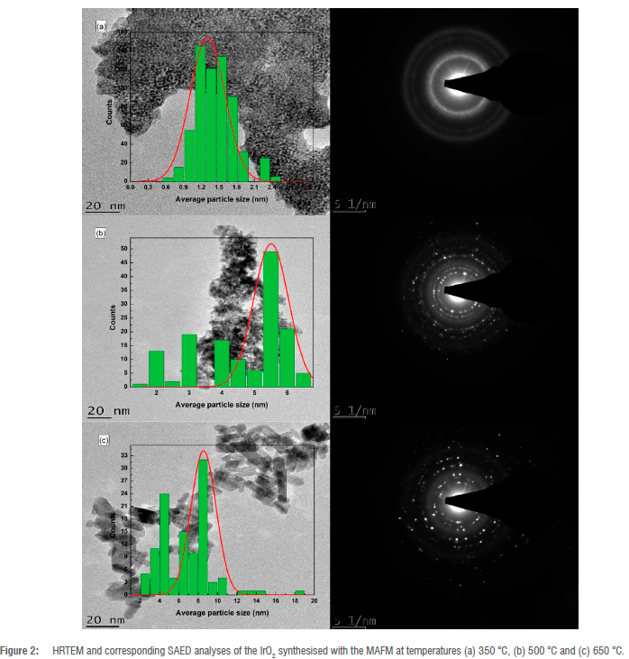
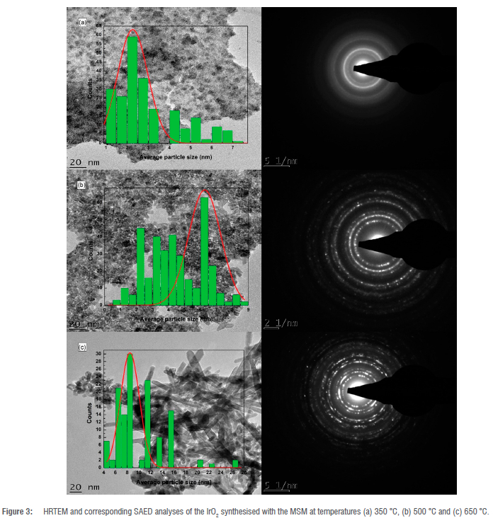
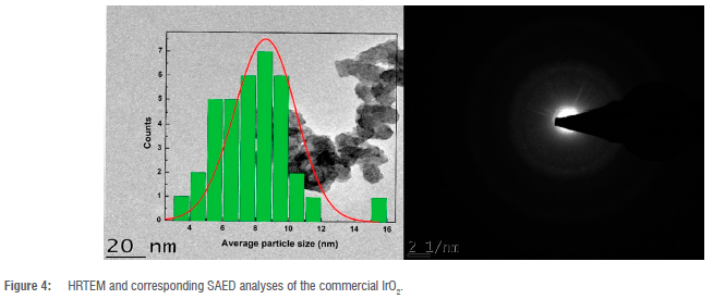
HRTEM analysis was used to study the morphology of the IrO2 catalysts synthesised with the MAFM and MSM. Sample MAFM-350 showed well-dispersed uniform spherical particles with sizes ~1.05 nm (Figure 2a). The corresponding selected area electron diffraction (SAED) image in Figure 2a confirmed the amorphous nature of MAFM-350 with the displayed concentric circles. MAFM-500 (Figure 2b) had cubic-shaped particles, ~5.48 nm, whereas MAFM-650 (Figure 2c) had a combination of cubic and cylindrical-shaped particles, ~ 8.68 nm. The bright dotted rings in the corresponding sAeD images of Figure 2b and 2c confirmed the crystalline natures of MAFM-500 and MAFM-650. Subramanian et al.24 observed similar SAED patterns for IrO2 catalysts synthesised at higher temperatures. The MSM-350 also had spherical-shaped particles with sizes ~2.31 nm (Figure 3a). The SAED pattern for MSM-350 was like that of MAFM-350, indicating amorphous materials. Figure 3b shows a combination of cubic and cylindrical particles for MSM-500 with sizes of ~6.15 nm. At increased temperatures, Ahmed et al.16 also obtained cylindrical-shaped IrO2 particles when using the MSM. The MSM-650 consisted of different particle shapes (spherical, cubic and cylindrical), each with particle diameter sizes of ~8.84 nm (Figure 3c). Similar to MAFM, IrO2 synthesised via the MSM at temperatures 500 °C and 650 °C showed increased crystallinity as confirmed by the SAED patterns in Figure 3b and 3c, respectively. Puthiyapura et al.18 suggested that the difference in morphology may be due to the difference in IrO2 preparation methods. Figure 4 shows the larger spherical-shaped particle sizes, ~8.96 nm, of the commercial IrO2, which confirmed the particle size estimated with the Scherrer formula. It can be assumed that lower crystallinity and smaller particle sizes may have higher geometric surface areas that increase the OER catalytic activity.18,22
The BET surface areas of the IrO2 catalysts were measured using N2 adsorption-desorption analysis. The BET surface area is given as the average diameter of the particles by determining the particle-size-dependent area and the charge-deduced area.25 The BET surface areas of the IrO2 catalysts are summarised in Table 1. As the synthesis temperature for the MAFM and MSM was increased, the BET surface areas of the IrO2 catalysts decreased. MAFM-350 had the highest BET surface area of 216.23 m2/g. The IrO2 catalysts synthesised via the MAFM had notably higher BET surface areas compared to MSM counterparts. This observation corresponds to the crystallite sizes measured from the HRTEM and the crystallite/particle sizes calculated from XRD. Baik et al.12 observed a similar increase in IrO2 catalysts surface area with decreasing MAFM synthesis temperatures, whereas Ahmed et al.16 observed a similar trend in BET surface areas for their IrO2 synthesised with the MSM. Furthermore, the commercial IrO2 had the smallest BET surface area, which may influence the sample's overall OER activity.
Electrochemical characterisation
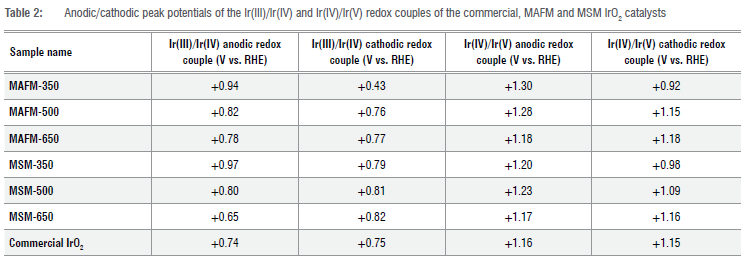
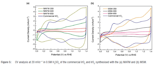
The cyclic voltammograms were obtained in a potential window of 0 and +1.4 V versus RHE with a potential scan rate of 20 mVs-1. The cyclic voltammograms seem to be influenced by the synthesis temperatures since there is a slight shift in the two redox couples, Ir(III)/Ir(IV) and Ir(IV)/Ir(V), as shown in Table 2. IrO2 catalysts typically display a lowering in current density and charge as the synthesis temperatures are increased.7,22,26 Heat treatment is known to dehydrate and crystallise the IrO2 material, thereby reducing the utilisation of Ir atoms participating in reactions to as low as 1%-2%.(7) In Figure 5a, the Ir(III)/Ir(IV) and Ir(IV)/Ir(V) redox couples for MAFM-350, MAFM-500 and MAFM-650 were observed. Between 0 and +0.65 V versus RHE, no charges were transferred for the MAFM-500 and MAFM-650 due to double-layer charging.22 In Figure 5b, the Ir(III)/Ir(IV) and Ir(IV)/Ir(V) redox couples for the MSM-350, MSM-500 and MSM-650 were observed, and the peak potentials are also summarised in Table 2. For the anodic potential scan, an additional pre-peak was seen at +0.35 and +0.59 V versus RHE for MAFM-350 and MSM-350, respectively. The peak can also be seen for the commercial IrO2. The cause of the peaks may be due to the coupled ion-electron transfer, formal potential distribution, relations in the layer or the change in mass transport within the layer as the potential change.22,27 The pre-peak is also believed to occur due to the oxidation of Ir3+ close to the metal/oxide interface and is accompanied by extensive water exchange.7 IrO2 synthesised at 500 °C and 650 °C does not exhibit these pre-peaks, ruling out the oxidation/reduction of a sodium layer impurity and also confirming the formation of a dehydrated IrO2 material due to a lack of the water exchange that takes place during the pre-peak formation. Therefore, the additional peaks are almost certainly due to the presence of active Ir(III) sites at slightly shifted oxidising/ reducing potentials. Additionally, the incomplete decomposition of the Ir-metal precursor in the oxide phase may also show the presence of active sites.28 Upon the cathodic potential scan at 0 V versus RHE, a strong negative 'tail' was seen for MAFM-500, MAFM-650, MSM-500 and MSM-650. This reflects their negative capacitive behaviour (Hads), involving the double-layer and pseudo- capacitances.22,28 These CV-shaped curves are like those found by Rasten et al.26, especially for the IrO2 synthesised at increased synthesis temperatures.
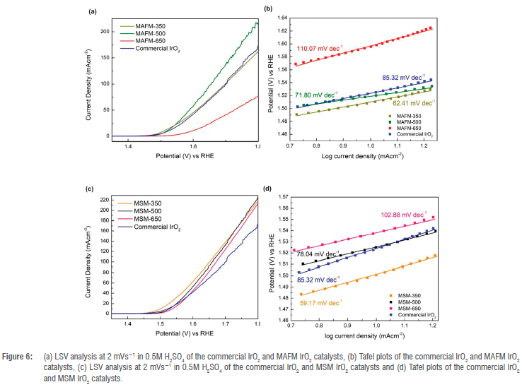
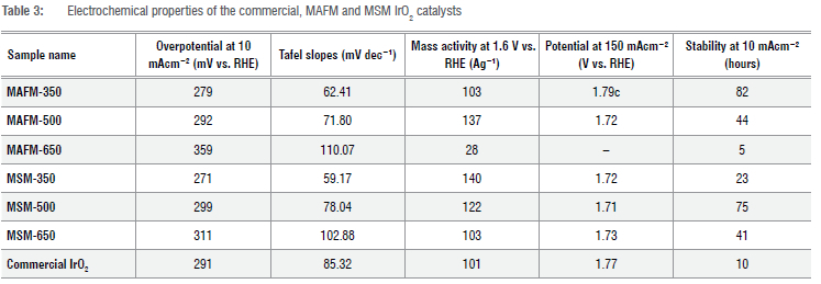
The polarisation curves were obtained using the LSV technique that was performed between +0.8 and +1.8 V versus RHE at a potential scan rate of 2 mVs-1. It is commonly understood that amorphous IrO2 displays higher OER activity due to complete IrO2 atom utilisation but suffers stability due to being prone to dissolution. In contrast, crystalline IrO2 lacks the activity due to low IrO2 atom utilisation and change in oxide stoichiometry towards the crystalline phase, but displays higher stability.29 Thus, a strong relationship exists between the structural properties and electrocatalytic performance due to the presence of a mixture of amorphous and crystalline IrO2.29 The polarisation curves of the IrO2 synthesised with the MAFM and MSM are shown in Figure 6a and 6c, respectively. The OER onset potentials of the synthesised IrO2 were found to be at ~1.5 V versus rHe due to the energy requirement during the H2O phase transition.30 MSM-350 had the lowest overpotential of 270 mV compared to 280 mV for MAFM-350. For MAFM, peak OER activity for IrO2 was observed at 500 °C, which is contrary to findings in the literature, which suggest that the amorphous IrO2 would be more active. For MSM, the lowest overpotential was observed for MSM-350. At lower current densities (10 mAcm-2), the MAFM-350 and MSM-350 had higher OER activities. However, at increased current densities (150 mAcm-2), the MAFM-500 and MSM-500 had higher OER activities. There were no results generated at 150 mAcm-2 for MAFM-650 due to the IrO2 degradation caused by the Ir dissolution.31 The performance difference between MAFM-650 and MSM-650 is quite notable, and the explanation is not clear as MAFM-650 had a higher BET surface and a similar CV to MSM-650. A possible explanation could be due to structural defects occurring during the formation of the Ir5+ surface where the OER takes place, which could also explain the higher overpotential at 10 mAcm-2. Surface reconstruction occurs during the OER process to expose the real active species while the pristine catalyst could be considered pre-catalysts.32 Different crystallinity induced by the synthesis temperature typically affects the dissolution rates of IrO2 with higher stability and lower activities being the result of higher temperatures. Rasten et al.26 also show improved OER activity of IrO2 synthesised at decreased temperatures. Most anodically produced IrO2 electrodes have a corresponding Tafel slope of about 44 mV dec-1.5,13 Figure 6b and 6d show the Tafel slopes of the IrO2 catalysts synthesised via the MAFM and MSM, respectively. For both synthesis methods, IrO2 synthesised at 350 °C exhibited the smallest Tafel slopes, i.e. 62.41 mV dec-1 for MAFM-350 and 59.17 mV dec-1 for MSM-350, while the Tafel slope magnitude increased with higher synthesis temperatures. IrO2 catalyst with a smaller Tafel slope generates current more efficiently when voltage is applied.13,14 Siracusano et al.19 synthesised IrO2 catalysts with an overall Tafel slopes of 80 mV dec-1. The Tafel slope consisted of an anodic contribution of 59.17 mV dec-1 and a cathodic contribution due to the OH adsorbed intermediates. Dang et al. developed a 1-T phase IrO2 with an overpotential of 235 mV and a Tafel slope of 49 mV dec-1; however, the synthesis method was highly challenging.33 Table 3 summarises the electrochemical properties of the IrO2 catalysts. The catalyst mass activities were determined at 1.6 V versus RHE. For the MAFM, MAFM-500 had the highest mass activity (137 Ag-1), whereas for the MSM, MSM-350 had the highest mass activity (140 Ag-1). The commercial IrO2 catalyst exhibited a mass activity of (101 Ag-1). For the MSM, there was a decreasing activity trend with the increase in synthesis temperature, while for the MAFM, peak activity was observed at a synthesis temperature of 500 °C. Higher mass activities may be attributed to catalyst nanostructures, which allow more exposure to the active sites.4 The commercial IrO2 had a lower OER activity when compared to the synthesised IrO2 from both the MAFM and MSM. The lower OER activities of MAFM-650, MSM-650 and commercial IrO2 can be attributed to the larger crystallite/particle sizes shown by the XRD and HRTEM analyses.
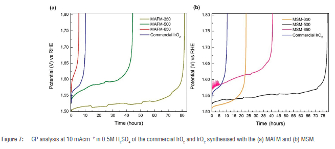
CP analysis was performed at 10 mAcm-2 until the potential reached a value of 1.8 V versus RHE. Performance degradation is normally attributed to dissolution of the IrO2 catalyst.34 Figure 7a shows the CP analysis of the IrO2 synthesised with the MAFM. MAFM-350 had the highest OER stability of ~82 h before reaching the cut-off potential. MAFM-500 and MAFM-650 were stable for ~44 h and ~5 h, respectively. Figure 7b shows the IrO2 synthesised with the MSM. MSM-500 had the highest OER stability of ~75 h. The stability of MSM-500 was on par with the stability of MAFM-350. MSM-650 was stable for ~41 h compared to ~23 h for MSM-350. The low stability of MSM-350 appears to be the result of the formation of a highly amorphous IrO2, which lacks the stable facets of IrO2 needed for stable OER performance. The stability of MSM-350 is more in line with the expected stability of an amorphous IrO2 catalyst compared to crystalline IrO2 catalysts. However, MAFM-350 showed stability that exceeded the stability of its more crystalline IrO2 counterparts, which is contrary to what is commonly expected from amorphous IrO2 catalysts. The high stability of MAFM-350 could be due to more active sites (deduced from high BET surface area) available for the OER. The detachment of bubble formation on MAFM-350 at an early stage of the analyses may have also contributed to the increased stability.35 The commercial IrO2 was stable for ~10 h, outperforming only MAFM-650. A possible explanation for the poor performance of MAFM-650 could be due to structural defects during formation of the Ir5+ oxidation state where the OER takes.35 The low stability of the commercial IrO2 could be due to both physical and chemical properties such as low surface area and the presence of metallic Ir. Banti et al.29 also observed a lower BET surface area and OER performance for this commercial IrO2 catalyst compared to their synthesised IrO2 catalysts. A summary of the catalysts' stabilities is provided in Table 3.
Conclusion
IrO2 catalysts suitable for the OER in PEMWE were successfully produced using MAFM and MSM. Both methods can be easily scaled for high-volume metal oxide production. The effects of synthesis method and temperature on the OER performance of the IrO2 catalysts were studied. It was found that MAFM and MSM influenced the OER performance of the IrO2 catalysts. However, no specific synthesis method showed both increased OER activity and stability. The effect of temperature on the IrO2 catalyst performance was different for the two synthesis methods. At 350 °C, the two methods yielded IrO2 catalysts with contrasting OER performance, i.e. MAFM-350 had significantly better stability but lower activity compared to MSM-350. At 500 °C, MAFM-500 and MSM-500 had similar activities; however, MSM-500 had significantly better stability. At 650 °C, MSM-650 had better activity and stability compared to MAFM-650 with MSM-650 having the poorest overall OER activity of all the IrO2 catalysts studied. The commercial IrO2 exhibited expected performance trends where amorphous IrO2 has good activity but low stability. The XRD analysis showed a phase transition, from amorphous to crystalline, as the synthesis temperature was increased from 350 °C to 650 °C. IrO2 catalysts synthesised at 350 °C were spherical shaped and amorphous. Above 500 °C synthesis temperatures, the IrO2 catalysts synthesised via MAFM had cubic and cylindrical shapes, whereas the IrO2 catalysts synthesised via MSM consisted of crystallites with different shapes. This study demonstrates that the physical properties of the IrO2 catalysts can be tailored through the synthesis method and the synthesis conditions, which can result in significant improvements in the OER performance of the IrO2 catalysts. Improved catalyst OER performance is essential to lower the catalyst loading requirements, which will in turn lower the costs associated with the catalyst component.
Acknowledgements
This work was funded by the Technology and Human Resources for Industry Programme (THRIP/19/31/08/2018) under the Department of Trade, Industry and Competition of the Republic of South Africa. We thank the anonymous reviewers for their valuable comments that improved this article.
Competing interests
We have no competing interests to declare.
Authors' contributions
S.K.: Data curation, investigation, formal analysis, conceptualisation, methodology, writing - original draft, writing - revisions and editing. C.F.: Visualisation, conceptualisation, methodology, formal analysis, writing -revisions and editing. S.P: Visualisation, funding acquisition, project administration, supervision.
References
1. International Renewable Energy Agency (IRENA). Green hydrogen cost reduction. Abu Dhabi: IRENA; 2020. p. 105. [ Links ]
2. Chen Z, Duan X, Wei W, Wang S, Ni BJ. Electrocatalysts for acidic oxygen evolution reaction: Achievements and perspectives. Nano Energy. 2020;78, Art. #105392. https://doi.org/10.1016/j.nanoen.2020.105392 [ Links ]
3. Yu J, Dai Y He Q, Zhao D, Shao Z, Ni M. A mini-review of noble-metal-free electrocatalysts for overall water splitting in non-alkaline electrolytes. Mater Reports Energy. 2021;1(2), Art. #100024. https://doi.org/10.1016/j.matre.2021.100024 [ Links ]
4. Liu Y, Liang X, Gu L, Zhang Y, Li GD, Zou X. Corrosion engineering towards efficient oxygen evolution electrodes with stable catalytic activity for over 6000 hours. Nat Commun. 2018;9(1):1-10. https://dx.doi.org/10.1038/s41467-018-05019-5 [ Links ]
5. Touni A, Grammenos OA, Banti A, Karfaridis D, Prochaska C, Lambropoulou D. Iridium oxide-nickel-coated titanium anodes for the oxygen evolution reaction. Electrochim Acta. 2021;390, Art. #138866. https://doi.org/10.1016/j.electacta.2021.138866 [ Links ]
6. Wang T, Cao X, Jiao L. PEM water electrolysis for hydrogen production: Fundamentals, advances, and prospects. Carbon Neutrality. 2022;1(1):1-19. https://doi.org/10.1007/s43979-022-00022-8 [ Links ]
7. Geiger S, Kasian O, Shrestha BR, Mingers AM, Mayrhofer KJJ, Cherevko S. Activity and stability of electrochemically and thermally treated iridium for the oxygen evolution reaction. J Electrochem Soc. 2016;163(11):F3132-F3138. https://doi.org/10.1149/2.0181611jes [ Links ]
8. Gupta SK, Mao Y. A review on molten salt synthesis of metal oxide nanomaterials: Status, opportunity, and challenge. Prog Mater Sci. 2021;117, Art. #100734. https://doi.org/10.1016/j.pmatsci.2020.100734 [ Links ]
9. Adams R, Shriner R. Platinum oxide as a catalyst in the reduction of organic compounds III: Preparation and properties of the oxide of platinum obtained by the fusion of chloroplatinic acid with sodium nitrate. J Am Chem Soc. 1923;9:2171-2179. https://doi.org/10.1021/ja01662a022 [ Links ]
10. Liu Y, Wang C, Lei Y, Liu F, Tian B, Wang J. Investigation of high-performance IrO2 electrocatalysts prepared by Adams method. Int J Hydrogen Energy. 2018;43(42):19460-19467. https://doi.org/10.1016/j.ijhydene.2018.08.196 [ Links ]
11. Jorge AB, Dedigama I, Miller TS, Shearing P Brett DJL, McMillan PF. Carbon nitride materials as efficient catalyst supports for proton exchange membrane water electrolyzers. Nanomaterials. 2018;8(6), Art. #432. https://doi.org/10.3390/nano8060432 [ Links ]
12. Baik C, Lee SW, Pak C. Glycine-induced ultrahigh-surface-area IrO2@IrOx catalyst with balanced activity and stability for efficient water splitting. Electrochim Acta. 2021;390, Art. #138885. https://doi.org/10.1016/j_electacta.2021.138885 [ Links ]
13. Cheng J, Zhang H, Ma H, Zhong H, Zou Y. Preparation of Ir0.4Ru0.6MoxOy for oxygen evolution by modified Adams' fusion method. Int J Hydrogen Energy. 2009;34(16):6609-6613. http://dx.doi.org/10.1016/j.ijhydene.2009.06.061 [ Links ]
14. Lim J, Kang G, Lee JW, Jeon SS, Jeon H, Kang PW, et al. Amorphous Ir atomic clusters anchored on crystalline IrO2 nanoneedles for proton exchange membrane water oxidation. J Power Sources. 2022;524, Art. #231069. https://doi.org/10.1016/j.jpowsour.2022.231069 [ Links ]
15. Yuasa M. Molten salt synthesis of Nb-doped TiO2 rod-like particles for use in bifunctional oxygen reduction/evolution electrodes. Ceram Int. 2022;48(10): 14726-14735. https://doi.org/10.1016/j.ceramint.2022.02.009 [ Links ]
16. Ahmed J, Mao Y. Ultrafine iridium oxide nanorods synthesized by molten salt method toward electrocatalytic oxygen and hydrogen evolution reactions. Electrochim Acta. 2016;212:686-693. https://dx.doi.org/10.1016/j.electacta.2016.06.122 [ Links ]
17. Carmo M, Fritz DL, Mergel J, Stolten D. A comprehensive review on PEM water electrolysis. Int J Hydrogen Energy. 2013;38(12):4901-4934. https://doi.org/10.1016/j.ijhydene.2013.01.151 [ Links ]
18. Puthiyapura VK, Pasupathi S, Basu S, Wu X, Su H, Varagunapandiyan N. RuxNb1-xO2 catalyst for the oxygen evolution reaction in proton exchange membrane water electrolysers. Int J Hydrogen Energy. 2013;38(21):8605-8616. https://doi.org/10.1016/j.ijhydene.2013.04.100 [ Links ]
19. Siracusano S, Baglio V Di Blasi A, Briguglio N, Stassi A, Ornelas R. Electrochemical characterization of single cell and short stack PEM electrolyzers based on a nanosized IrO2 anode electrocatalyst. Int J Hydrogen Energy. 2010;35(11):5558-5568. https://dx.doi.org/10.1016/j.ijhydene.2010.03.102 [ Links ]
20. Aricò AS, Siracusano S, Briguglio N, Baglio V Di Blasi A, Antonucci V. Polymer electrolyte membrane water electrolysis: Status of technologies and potential applications in combination with renewable power sources. J Appl Electrochem. 2013;43(2):107-118. https://doi.org/10.1007/s10800-012-0490-5 [ Links ]
21. Hu JM, Meng HM, Zhang JQ, Cao CN. Degradation mechanism of long service life Ti/IrO2-Ta2O5 oxide anodes in sulphuric acid. Corros Sci. 2002;44(8):1655-1668. https://doi.org/10.1016/S0010-938X(01)00165-2 [ Links ]
22. Felix C, Bladergroen BJ, Linkov V, Pollet BG, Pasupathi S. Ex-situ electrochemical characterization of IrO2 synthesized by a modified Adams fusion method for the oxygen evolution reaction. Catalysts. 2019;9(4), Art. #318. https://doi.org/10.3390/catal9040318 [ Links ]
23. Zhang Y, Wang C, Mao Z, Wang N. Preparation of nanometer-sized SnO2 by the fusion method. Mater Lett. 2007;61(4-5):1205-1209. https://doi.org/10.1016/j.matlet.2006.06.083 [ Links ]
24. Subramanian V, Hall SC, Smith PH, Rambabu B. Mesoporous anhydrous RuO2 as a supercapacitor electrode material. Solid State Ion. 2004;175(1-4):511-515. https://doi.org/10.1016/j.ssi.2004.01.070 [ Links ]
25. Ma Z, Zhang Y, Liu S, Xu W, Wu L, Hsieh YC, et al. Reaction mechanism for oxygen evolution on RuO2, IrO2, and RuO2@IrO2 core-shell nanocatalysts. J Electroanal Chem. 2018;819:296-305. https://doi.org/10.1016/j.jelechem.2017.10.062 [ Links ]
26. Rasten E, Hagen G, Tunold R. Electrocatalysis in water electrolysis with solid polymer electrolyte. Electrochim Acta. 2003;48(25-26):3945-3952. https://doi.org/10.1016/j.electacta.2003.04.001 [ Links ]
27. Steegstra P, Busch M, Panas I, Ahlberg E. Revisiting the redox properties of hydrous iridium oxide films in the context of oxygen evolution. J Phys Chem. 2013;117:20975-20981. https://doi.org/10.1021/jp407030 [ Links ]
28. Grupioni AAF, Arashiro E, Lassali TAF. Voltammetric characterization of an iridium oxide-based system: The pseudocapacitive nature of the Ir0.3Mn0.7O2 electrode. Electrochim Acta. 2002;48(4):407-418. https://doi.org/10.1016/S0013-4686(02)00686-2 [ Links ]
29. Banti A, Papazisi KM, Balomenou S, Tsiplakides D. Effect of calcination temperature on the activity of unsupported IrO2 electrocatalysts for the oxygen evolution reaction in polymer electrolyte membrane water electrolyzers. Molecules. 2023;28(15), Art. #5827. https://doi.org/10.3390/molecules28155827 [ Links ]
30. Han SB, Mo YH, Lee YS, Lee SG, Park DH, Park KW. Mesoporous iridium oxide/ Sb-doped SnO2 nanostructured electrodes for polymer electrolyte membrane water electrolysis. Int J Hydrogen Energy. 2020;45(3):1409-1416. https://doi.org/10.1016/j.ijhydene.2019.11.109 [ Links ]
31. Feng Q, Yuan XZ, Liu G, Wei B, Zhang Z, Li H. A review of proton exchange membrane water electrolysis on degradation mechanisms and mitigation strategies. J Power Sources. 2017;366:33-55. https://doi.org/10.1016/j.jpowsour.2017.09.006 [ Links ]
32. Chen S, Ma L, Huang Z, Liang G, Zhi C. In situ/operando analysis of surface reconstruction of transition metal-based oxygen evolution electrocatalysts. Cell Reports Phys Sci. 2022;3(1), Art. #100729. https://doi.org/10.1016/j.xcrp.2021.100729 [ Links ]
33. Dang Q, Lin H, Fan Z, Ma L, Shao Q, Ji Y et al. Iridium metallene oxide for acidic oxygen evolution catalysis. Nat Commun. 2021;12(1), Art. #6007. https://doi.org/10.1038/s41467-021-26336-2 [ Links ]
34. Ouattara L, Fierro S, Frey O, Koudelka M, Comninellis C. Electrochemical comparison of IrO2 prepared by anodic oxidation of pure iridium and IrO2 prepared by thermal decomposition of H2IrCl6 precursor solution. J Appl Electrochem. 2009;39(8):1361-1367. https://doi.org/10.1007/s10800-009-9809-2 [ Links ]
35. Spöri C, Kwan JTH, Bonakdarpour A, Wilkinson DP Strasser P The stability challenges of oxygen evolving catalysts: Towards a common fundamental understanding and mitigation of catalyst degradation. Angew Chemie Int Ed. 2017;56(22):5994-6021. https://doi.org/10.1002/anie.201608601 [ Links ]
 Correspondence:
Simoné Karels
Email: simonekarels2012@gmail.com
Received: 19 May 2023
Revised: 04 Dec. 2023
Accepted: 09 Dec. 2023
Published: 27 Mar. 2024
Editor: Priscilla Baker
Funding: South African Department of Trade, Industry and Competition (THRIP/19/31/08/2018)

