


Services on Demand
Article
 English (pdf)
 Article in xml format
 Article references
Indicators

Related links
-
 Cited by Google
 -
 Similars in Google
Share

 Permalink
South African Journal of Science
On-line version ISSN 1996-7489
Print version ISSN 0038-2353
S. Afr. j. sci. vol.118 n.11-12 Pretoria Nov./Dec. 2022
http://dx.doi.org/10.17159/sajs.2022/12566
RESEARCH ARTICLE
Investigation of the suitability of activated and non-activated bentonites from the Imerys Mine (South Africa) for geosynthetic clay liners
Ahmad Patel; Egerton D.C. Hingston; Molla Demlie
School of Agriculture, Earth and Environmental Sciences, University of KwaZulu-Natal. Durban, South Africa
ABSTRACT
Geosynthetic clay liners (GCLs) have become a suitable substitute for compacted clay liners used for prevention of leachate percolation from landfills and tailings dams into the groundwater system. The characteristics of most bentonites is improved through a process of activation by mixing with soda ash (Na2CO3). This paper presents the investigation results of the suitability of bentonites from the Imerys Mine in South Africa for use in GCLs. Both activated and non-activated bentonites were investigated through X-ray diffraction (XRD) analysis and swell index, fluid loss, plate water absorption and Atterberg limits tests. The XRD analysis results indicate that the activated and non-activated bentonite have a smectite content of 58% and 67%, respectively. The swell index of non-activated bentonite was significantly lower than that of activated bentonite. The activated bentonite samples tested at different times subsequent to activation revealed that a minimum of 4 weeks of activation time is required to fully activate it to the ideal soda ash to bentonite ratio of 1:16. The fluid loss tests displayed results slightly above the required minimum of 18 mL because of the low swell index of the bentonites tested. The activated and non-activated bentonites have absorption capacities of 133% and 121 %, respectively. The plasticity index of the activated bentonite is 101%, 15% higher than the non-activated bentonite. The overall results concluded that the Imerys bentonite is a medium-quality bentonite with borderline index properties that requires at least 4 weeks of beneficiation to achieve complete activation to suitably be used as GCLs.
SIGNIFICANCE: The significance of this paper is the beneficiation process of bentonite in the geotextile industry
This study is relevant to geotechnical engineers, environmental geologists, engineering geologists and other related professionals working with geosynthetic clay liners whereby bentonite is the key ingredient.
The study provides an optimum ratio of bentonite to sodium carbonate and the required time for beneficiation.
We further recommend that quality control measures should be implemented to ensure complete activation of bentonite, including the blending process of different qualities of bentonite.
Keywords: bentonite activation, fluid loss, geosynthetic clay liners, smectite clay, swell index
Introduction
Geosynthetic clay liners (GCLs) have gained much attention over the past decade and have become a common and reliable substitute for compacted clay liners.1,2 The applications of GCLs span from civil engineering to environmental protection such as liners in water impoundment facilities and as composite liners in landfills.1,3-5 GCLs are thinly manufactured hydraulic barriers comprising a layer of sodium bentonite encased between two geotextiles or geomembrane sheets.6 However, the fundamental component of GCLs is bentonite.1,5,7 Bentonite exists as either sodium bentonite or calcium bentonite, depending on the type of montmorillonite and/or the predominant exchangeable ion it contains. Sodium bentonite has higher water retention characteristics and better swelling properties than calcium bentonite and consequently offers better efficacy as a hydraulic barrier.8 Generally, the typical sodium bentonite used in GCLs will contain 60-85% montmorillonite.29 GCLs are hydrated to a certain degree of saturation through the uptake of water from the subsoil subsequent to its installation. When the bentonite absorbs water under confinement, it swells, thereby reducing the void ratio. Thus, a lower void ratio can be obtained after the saturated condition, which results in a better performance of the GCL in terms of the limited hydraulic conductivity.9
The primary function of GCLs is to act as hydraulic barriers in landfills and tailings dams to contain leachates and tailings, respectively.1 Therefore, GCL investigations are aligned to properties that relate to hydraulic conductivity, such as fluid loss, free swell and absorption. Sodium bentonites have a high swelling capacity compared to bentonites with low amounts of sodium which have a much lower swelling capacity. However, the low swelling capacity of low sodium bentonites can be improved by treatment with sodium carbonate or soda ash (Na2CO3). This process increases the concentration of exchangeable sodium ions within the bentonite, effectively producing sodium exchanged bentonite.10 The process of mixing bentonite with soda ash is called sodium activation and the resulting bentonite is said to be sodium activated or simply activated bentonite. This is primarily responsible for the high swell index and sealing ability of bentonite.11
As various users require bentonite of a certain specification, all mined bentonites undergo some processing prior to sale. Problems such as inadequate swell index defeat the main purpose of a GCL and destroy its primary function as a hydraulic barrier. The Imerys Mine in the Western Cape Province of South Africa mines bentonite for the manufacturing of GCLs. However, information related to fluid loss and swell index performance requirements for use as GCLs has not been studied in detail. Additionally, the comparative performance of the non-beneficiated bentonite relative to beneficiated bentonite and the effect of time on the beneficiation process of bentonite from the mine used in the GCLs has not been researched. Thus, this study reports the investigation results of the suitability of bentonite from the Imerys Mine for use in GCLs, the comparative performance of the non-beneficiated and beneficiated bentonites and the effect of time on the beneficiation process of bentonite from the mine.
Geosynthetic clay liners
GCLs comprise a thin layer of either sodium bentonite or calcium bentonite, bonded between a geomembrane or geotextile.1,5,12,13 Those GCLs using geotextiles sandwich the bentonite by needle-punching, stitching or by using a non-polluting adhesive.1 Needle-punched GCLs comprise an encasing nonwoven filament geotextile where the needle punching process pierces fibres from the upper geotextile to the bottom geotextile.5 This process entangles the fibres to the bottom geotextile, bonding the sheathing layers together. Bonding may also be achieved through heating, causing the piercing geotextile to fuse to the bottom geotextile. The stitching method involves sewing the geotextiles together using stitching bonded yarns.5 Bentonite in the geomembrane supported GCL is bonded to the geomembrane using a non-polluting adhesive. The adhesive is mixed with the bentonite and pasted onto a geomembrane.1,5
Although there are many types of GCLs, the fundamental difference is the type of bentonite used. The bentonites used in GCLs can either be granular or powdered and sodium or calcium. The main advantages of GCLs are limited thickness, good endurance to differential settlements of underlying soil or waste, simple installation and low cost.1
Bentonite deposits at Heidelberg and the Imerys Bentonite Mine
The Imerys Bentonite Mine is located near the town of Heidelberg approximately 230 km east of Cape Town in the Western Cape Province of South Africa (Figure 1). The Mine is situated within the Heidelberg-Riversdale Basin, which hosts the Uitenhage Group rocks.
Geologically, the Uitenhage Group is composed of clastic sediments presented as alluvial fans, braided rivers, and lacustrine sediments.14 It comprises eight formations, namely: the Hartenbos Formation, the Buffelskloof Formation, the Robberg Formation, the Sundays River Formation, the Brenton Formation, the Infanta Formation, the Kirkwood Formation and the Enon Formation. The bentonite deposits are hosted in the Kirkwood Formation, which is a volcano-sedimentary succession of intercalated sandstones and lacustrine mudstones, with subordinate conglomerates, interbedded with volcanoclastic deposits.15-17 During the formation of the Heidelberg-Riversdale basin, alkaline volcanic events occurred, leading to the deposition of volcanic ash in a salty lacustrine environment.18 This saltwater-volcanic ash interaction led to the formation of sodium bentonite. The glass components of the ashes were chemically altered in this low energy environment and consolidated into distinct clay layers that form the Heidelberg-Riversdale bentonite deposits in the study area.19
Alteration of volcanic glass may occurthrough vapour-phase crystallisation, burial diagenesis, contact metamorphism, hydrothermal activity, and by hydrolysis. As the conversion of volcanic glass to smectites involves movement of elements to and from the volcanic glass, leaching of alkali elements and high Mg2+/H+ are required to form smectites during the alteration of volcanic glass. Thus, the loss of alkalis and a high magnesium activity promote the formation of smectite.20
There are multiple bentonite horizons mined at Heidelberg. These horizons range between 1 m and 1.7 m in thickness and are mostly overlain by mudstone or siltstones.17 It is estimated that the bentonite reserve at the Heidelberg region is about one million tons.21
The method of mining of bentonite at the Imerys Mine is a shallow open pit method, which does not require extensive engineered benches or specific mining techniques. Because bentonite is soft, drilling and blasting are not required, as in the case of conventional mines; however, construction of an access ramp from the overburden is required to allow trucks and excavators into the pit. The pits are excavated to the bentonite layer, which is between 10 m and 20 m below the surface, and the bentonite is removed using an excavator. The excavator simply cuts through the bentonite with the excavator bucket which is then loaded onto tipper trucks for transportation to the processing plant. The pits are refilled and rehabilitated after all the bentonite is mined. As the bentonite quality often varies among several pits, the bentonite from different pits is interlayered to ensure a uniform quality. Thereafter, slices are taken vertically to create a blend of all qualities, and subsequently processed. This method of mixing bentonites of low quality with higher quality bentonites produces a product that has an average acceptable industry standard. It also controls the amount of soda ash that is required, and so to create a fairly consistent mix of bentonite, a fixed amount of soda ash can be added to every batch mined, which also eliminates the need for constantly changing machinery settings and constant quality testing of the bentonite.
Methods and materials
Samples were collected from stockpiles of activated and non-activated bentonite from the Imerys Bentonite Mine. The conversion process of natural sodium bentonite to activated bentonite follows a procedure by which approximately 1-2% of soda ash is added to the bentonite via a feed hopper containing soda ash. The activated bentonite then passes through a rotary drier where all excess moisture is removed and thereafter the dried bentonite is added to a roller crusher where it is milled to a fine powder. Samples of approximately 5 kg from the activated and non-activated bentonite were packed in thick polyethylene bags and then stored in a controlled laboratory environment at 24 °C and 65% relative humidity. Samples were taken randomly from the storage bags for various tests including swell index, fluid loss, plate water absorption, XRD and Atterberg limits following standard procedures.22-24
Laboratory analyses
XRD analysis was conducted on the bentonites in order to determine their bulk mineralogical composition. The samples were prepared by drying 10 g of activated and non-activated bentonite in a laboratory oven at 100 °C. The dried bentonite was then crushed with a mortar and pestle and sieved using a 75-μm sieve; 100% passing through the 75-μm sieve were analysed following standard procedures at the XRD Analytical and Consulting Laboratory in Pretoria, South Africa.25,26
Swell index test
The swell index test was undertaken following the American Society for Testing and Materials (ASTM) standard.22 The method involved drying 15 g of bentonite in a laboratory oven at 100 °C, to a constant mass for a minimum of 16 h. The dried sample was then crushed to a fine powder using a mortar and pestle. The powdered bentonite was sieved with the 75-/um aperture sieve and samples passing the 75 μm were used for the tests. A total mass of 2 g of the sieved powdered bentonite was placed in 0.1-g increments every 10 min in a 100-mL graduated cylinder filled with 90 mL of distilled water. Once the entire 2-g sample was added to the cylinder, the water was then topped to 100 mL and left undisturbed for 16 h. The temperature, pH and electrical conductivity (EC) of the water were measured before and after each test. Initially, three samples were tested, with Sample 1 being activated, processed (dried and milled) sodium bentonite; Sample 2 unprocessed, activated sodium bentonite and Sample 3 unprocessed, non-activated sodium bentonite. Activation of Samples 1 and 2 occurred at Imerys Mine, whereby approximately 1 % soda ash was added to the bentonite.
To further investigate the effect of time on the beneficiation process, three samples of bentonite were activated in the laboratory with different amounts of soda ash: 2 g, 4 g and 6 g of soda ash was mixed with non-activated bentonite Samples A, B and C, respectively, resulting in ratios of soda ash to bentonite of 1:50,1:25 and 1:16, respectively. Swell index tests were conducted on each sample within 24 h, and 1 week, 2 weeks and 3 weeks, after activation.
Fluid loss
The fluid loss test evaluates the capability of a bentonite suspension to form a hydraulic barrier. Liu et al.4 used fluid loss as a quick method to evaluate the hydraulic conductivity of bentonite within GCLs. They reported that the hydraulic performance of GCLs depends directly on the swelling capacity of the bentonite component when in contact with water. Fluid loss tests in this study were conducted at Golder Laboratories in the USA. It was only possible to conduct three fluid loss tests each for activated and non-activated bentonites. The tests were conducted in accordance with the ASTM standard.23 The fluid loss is calculated as twice the amount of water collected in 22.5 min after the cell has been given 7.5 min to equilibrate, as indicated in Equation 1:

Plate water absorption test
The plate water absorption test was designed to assess the binding ability of bentonite clay binders for iron ore pelletisation.27 The procedure originated from the ASTM E946-92 testing method, which was initially intended to test the absorption of dried bentonite over a specific period. Balling or pelletising is a process whereby iron ore is processed into a pellet or ball. Bentonite acts as the binding agent in the production of iron ore pellets.28 The plate water absorption test involves partially submerging a sintered alumina plate in distilled water in a bath. Approximately 2 g of dried and powdered bentonite was placed on a 9-cm-diameter filter paper. The bentonite was spread over the filter paper within a 5-cm-diameter template. The paper and bentonite were placed on the semi-submerged sintered plate to absorb water for 18 h, where the height of the sample above the water surface was 1.2 cm, and the bath was sealed. The water temperature was recorded before the test and 18 h after the test. Then, the bentonite and filter paper were weighed, and the average weight of the wet filter paper was subtracted from the weight of the hydrated filter paper plus the bentonite. This average weight was determined prior to testing by allowing four filter papers to absorb water over an 18-h period without any bentonite. The water absorbed by the bentonite, or the absorption, is the percentage of water absorbed, calculated as a percentage of the dry mass following Equation 2.

where Ww is the weight of the hydrated bentonite and Wd is the weight of the dry bentonite in grams.
Atterberg limits
The Atterberg limit is a measure of the critical moisture content, as a percentage of the dry mass, at which a clay soil changes consistency.29 In this study, Atterberg limits, i.e. the liquid limit, the plastic limit and the plasticity index, were determined using powdered bentonite following the British Standard.30
Results and discussion
Mineralogical composition and swelling potential of Imerys bentonite
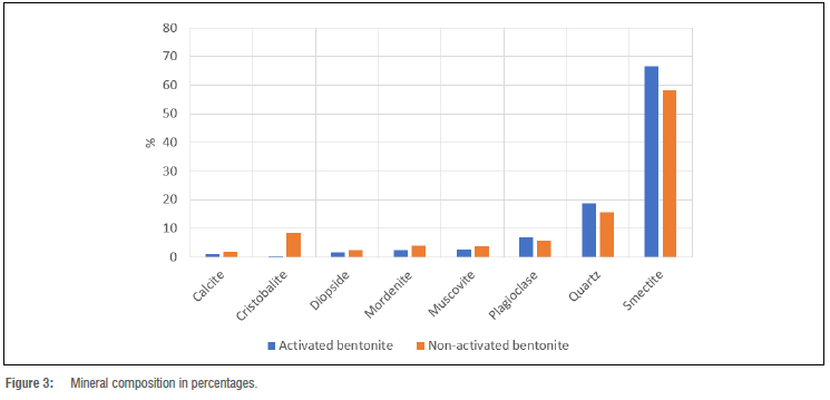
The results of the XRD analysis for both the activated bentonite and non-activated bentonite are shown in Figure 2. The XRD patterns of the activated bentonite and non-activated bentonite as shown in Figure 2 indicate peaks at 29 values of 25, 30 and 60, which are characteristic of montmorillonite. Typically, bentonites contain around 60% montmorillonite.2 Accordingly, the bentonites from the Imerys Mine can be regarded as typical bentonite as its average smectite content is around 60%. The other peaks in Figure 2 indicate a substantial amount of impurities in both the activated and non-activated bentonites (Figure 3), where the most significant is quartz. According to Gates and Churchman31, bentonites with impurities will not have a desirable swell index due to the impact of the non-smectite impurities on the physical and chemical properties. The most detrimental types of impurities are non-swelling impurities which diminish the swelling ability of the bentonites.31 In summary, the quantity of smectite and the chemical composition of bentonite critically influence permeability and performance as a sealing material.32
The results of the swell index tests conducted on the activated and non-activated bentonites are shown in Table 1. The measured temperature, pH and EC of the distilled water before and after each test for both the activated and non-activated bentonite are also shown in Table 1. The average swell index obtained for the activated bentonite is 15.6 mL/2 g compared to 9.8 mL/2 g determined for the non-activated bentonite. The results from the swell index tests show that the activated bentonite has a higher swell index than the non-activated bentonite (Table 1). This is because the activated bentonite has additional exchangeable sodium ions due to the activation process. Because sodium ions have a large hydration radius, they are primarily responsible for the swelling of bentonites11, and this is why the activated bentonite has a higher swell index than the non-activated bentonite. An increase of about 5-6 mL/2 g swell index was observed between the activated bentonite and the non-activated bentonite, amounting to about a 50-70% increase in swell. Figure 4 illustrates the difference in swell index between the activated bentonite and non-activated bentonite.

The swell index for the activated bentonite did not reach the minimum requirement of 24 mL/2 g as per the ASTM22 standard. Further investigation was conducted to ascertain why the swell index did not reach the required specification by undertaking swell index tests of the activated bentonite at specific time intervals after activation. The results indicate that at least 1 month is required after activation before the bentonite acquires the desired swell index. Therefore, as the bentonite activation process is an ionic exchange process whereby the sodium content of the bentonite is enhanced at a molecular level, time is required for the reaction to reach completion.33 Compared to the activated bentonites at Imerys Mine, the Wyoming bentonite, commonly referred to as MX80 bentonite, has a swell index of approximately 27 mL/2 g.34 The high swell index of the Wyoming bentonite compared to the activated bentonites tested in this study is attributed to the high montmorillonite content in the Wyoming bentonite.
As seen in Table 2, the temperature and the pH of the solution remained nearly unchanged, indicating that no exothermic or endothermic chemical reaction took place between the de-ionised water and the activated and non-activated bentonites. As distilled water (de-ionised) was used, it can be assumed that no isomorphous ionic substitution took place that could have affected the swelling potential of the bentonite. However, the EC increases substantially during the course of the swell test. The initial ECs of the distilled water used for the activated bentonite and non-activated were 5/uS/cm and 3/uS/cm, respectively. The EC increased to a maximum of 705 /uS/cm for the activated bentonite and 194 /uS/cm for the non-activated bentonite, indicating that a substantial concentration of ions dissolved into solution. Furthermore, the EC of the activated bentonite solution is higher than that of the non-activated bentonite due to the ionic exchange of sodium allowing the dissolution of accessory minerals into the solution. In this case, the most readily dissolving minerals from natural bentonites are obviously carbonates and sulfates.35

Effect of time on the beneficiation process
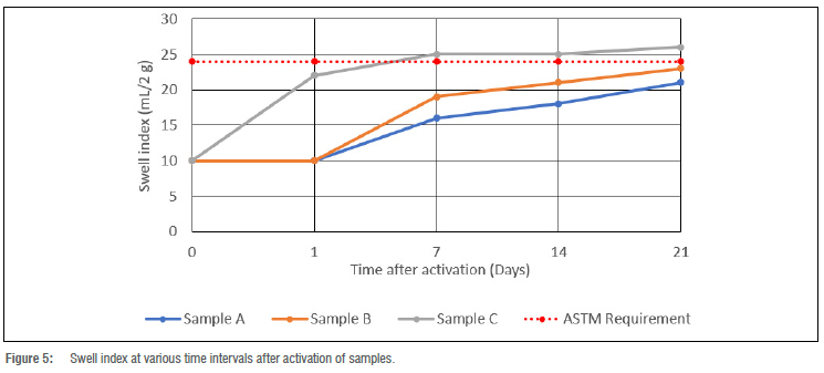
Activation of three samples was conducted in the Laboratory to investigate the effect of time on the beneficiation of bentonites. The results of the swell index tests conducted on the three samples (labelled as A, B and C) at time intervals of 1 day, 7 days, 14 days and 21 days after activation are shown in Table 2. Samples A, B and C had a soda ash to bentonite ratio by mass of 1:50,1:25 and 1:16, respectively.
Plots of swell index versus time after activation are shown in Figure 5. The plots show that Samples A and B showed no increase in swell index within 24 h, which is explained in terms of the fact that low amounts of sodium activation did not affect the bentonite over such a short period.
However, Sample C showed an increase in swell index after 24 h of activation, although lower than the required minimum. All three samples showed a marked increase in swell index 7 days after the activation process. Although there was no change in the swell index for Samples A and B after 24 h, Sample B swelled significantly more than Sample A beyond 24 h. The most significant increase in swell for Samples A and B was after 1 week, with Samples A and B increasing by 6 mL/2 g and 9 mL/2 g of swell, respectively, from the initial swell index of 10 mL/2 g. However, 2 weeks of activation time was not sufficient for Samples A and B to reach the required minimum value of 24 mL/2 g. Sample C, however, attained the required minimum value after 1 week of activation. Thus, Sample C represents the best ratio required for activation over a short period, with a soda ash to bentonite ratio of approximately 1:16. Although Sample C achieved the majority of the required swell within the first week after activation, the swell index was enhanced significantly at the start and thereafter levelled off. Samples A and B show a consistent increase in swell index over time but with variable rates. Swell indices for Samples A and B did not reach the benchmark 24 mL/2 g even after 3 weeks of activation.
Fluid loss and plate water absorption test results
The results of the fluid loss tests conducted on the activated and non-activated bentonites are shown in Table 3. Because fluid loss is indicative of the hydraulic conductivity, the activated bentonite is expected to have a lower fluid loss due to a higher swelling and hence sealing ability.4 The activated and non-activated bentonites tested in this study had average fluid losses of about 23 mL and 27 mL, respectively (Table 3). These measured fluid losses did not meet the 18 mL maximum fluid loss requirement set in the ASTM standard of bentonites used in GCLs.

Studies conducted by Shackelford et al.36 state that an increase in hydraulic conductivity in bentonites is mainly due to limited swelling. Thus, the high fluid losses measured in this study are attributed to a lack of sufficient swell. It is noted that low fluid loss indicates low flow through the bentonite barrier within a given time and therefore implies a low hydraulic conductivity. Furthermore, Lee and Shackelford37 investigated the effect of the quality of bentonite on its hydraulic conductivity and found that the hydraulic conductivity of high-quality bentonites is three times lower than that of low-quality bentonites. High-quality bentonite is distinguished by its higher montmorillonite content as well as a higher plasticity index.
This study shows that the quality of the raw bentonite produced at the Imerys Mine is of low quality prior to activation and incomplete beneficiation will result in a less desirable product. Therefore, as activation increases the quality of the bentonite to act as a hydraulic barrier, the beneficiation process may require additional time or additional treatment to achieve full activation.
On the other hand, the absorption ability of the bentonite was measured as the water content absorbed by the bentonite after a fixed period. The results of the plate water absorption tests for both the activated bentonite and non-activated bentonite as a percentage of dry mass are presented in Table 4. The average absorption for the activated bentonite was 133.6% whilst for the non-activated bentonite was 121.6%. Both the activated and non-activated bentonites absorbed water well above the dry mass of the respective samples. The activated bentonite absorbed 10% more water than the non-activated bentonite, which is the reason for the relatively increased swell and resultant decrease in the fluid loss, and thereby enhanced its sealing behaviour.38 Thus, the plate water absorption test indicates the bentonite's ability to swell and it is evident that the addition of soda ash increases the water absorption capabilities of bentonites and consequently its swelling potential and sealing effectiveness.

Results of the Atterberg limits tests
The Atterberg limits test results are presented in Table 5. The activated bentonite had a 9% higher liquid limit and 10% higher plasticity index compared to the non-activated bentonite, whilst the plastic limits and the linear shrinkage results were the same (Table 5). The liquid limit of bentonites is controlled by interparticle forces, the dominant being repulsion through osmotic activity which keeps the particles in a fixed configuration and prevents free movement.39 Strength results from the force of repulsion resisting displacement of particles in the shear plane. On the other hand, as the repulsion is decreased, particles move freely at lower liquid limits. Monovalent ions such as sodium increase the repulsion forces, enabling a higher liquid limit.39,40 Thus, activation of bentonites increases the concentration of Na+ thereby increasing the interparticle forces and increasing the swell index. Consequently, the activated bentonite has a higher liquid limit than the non-activated bentonite.

Conclusions
The abundance of bentonite deposits worldwide means GCLs are a common technology in many civil and environmental applications such as landfill hydraulic barriers, environmental protection barriers and as water impoundment liners. Similarly, activated powdered sodium bentonite from the Imerys Mine in the Western Cape Province of South Africa is used in the production of GCLs. The difference in the behaviour of activated and non-activated bentonites and the suitability of the Imerys sodium bentonite for use in GCLs were investigated against the important properties, including the bulk mineralogical composition, swell index, fluid loss, plate water absorption and Atterberg limits. The soda ash to non-activated bentonite ratio and the effect of time on the activation of the bentonite were also investigated.
The results show that the Imerys bentonite is made up of approximately 60% smectite and non-swelling impurities including quartz, calcite, diopside, mordenite, muscovite, and plagioclase. Although the swell index of the activated bentonite was 5 mL/2 g more than that of the non-activated bentonite, both the sodium activated and the non-activated bentonites failed to reach the required minimum of 24 mL/2 g within the required 24 h. In the case of activated bentonite, this result is attributed to incomplete activation. The fluid loss test for activated and non-activated bentonites produced results higher than the required minimum fluid loss standard of 18 mL, which is attributed to the low quality of the bentonite and its incomplete activation. All the test results indicate that the Imerys bentonite in South Africa is a medium-quality bentonite with borderline index properties that require beneficiation and time to achieve complete activation. The appropriate ratio that suits beneficiation is 1:16 and the required time for beneficiation is at least 4 weeks. Thus, it is recommended that quality control measures should be implemented to ensure complete activation of bentonite, including the blending process of different qualities of bentonite.
Acknowledgements
We thank the Imerys Mine for allowing us to undertake this study, the Kaytech Engineered Fabrics in Pinetown for allowing us to use its laboratory during the course of this study, and the National Research Foundation (South Africa) and University of KwaZulu-Natal for funding the research.
Competing interests
We have no competing interests to declare.
Authors' contributions
A.P.: Data collection, sample analysis, data analysis, validation, writing - initial draft, funding acquisition. E.D.C.H.: Conceptualisation, methodology, validation, student supervision, writing - revisions, project leadership, project management. M.D.: Methodology, validation, writing - revisions, project management.
References
1. Bouazza A. Geosynthetic clay liners. Geotext Geomembr. 2002;20(1 ):3-17. https://doi.org/10.1016/S0266-1144(01)00025-5 [ Links ]
2. Von Maubeuge K. Investigation of bentonite requirements for geosynthetic clay barriers. In: Zanzinger H, Koerner RM, Gartung E, editors. Clay geosynthetic barriers. Lisse: Swets and Zeitlinger; 2002. p. 155-163. https://doi.org/10.1201/9781003078777-19 [ Links ]
3. Rowe RK, Orsini C. Effect of GCL and subgrade type on internal erosion in GCLs under high gradients. Geotext Geomembr. 2003;21:1-24. http://dx.doi.org/10.1016/S0266-1144(02)00036-5 [ Links ]
4. Liu X Gates WP, Bouazza A, Rowe RK. Fluid loss as a quick method to evaluate hydraulic conductivity of geosynthetic clay liners under acidic conditions. Can Geotech J. 2013;51(2):158-163. https://doi.org/10.1139/cgj-2013-0241 [ Links ]
5. Kong DJ, Wu H-N, Chai J-C, Arulrajah A. State-of-the-art review of geosynthetic clay liners. Sustainability. 2017;9(11):2110. https://doi.org/10.3390/SU9112110 [ Links ]
6. Setz MC, Tian K, Benson CH, Bradshaw SL. Effect of ammonium on the hydraulic conductivity of geosynthetic clay liners. Geotext Geomembr. 2017;45:665-673. http://dx.doi.org/10.1016/j.geotexmem.2017.08.008 [ Links ]
7. Lin LC, Benson CH. Effect of wet-dry cycling on swelling and hydraulic conductivity of GCLs. J Geotech Geoenviron. 2000;126:40-19. https://doi.org/10.1061/(ASCE)1090-0241 (2000)126:1 (40) [ Links ]
8. Norrish K. The swelling of montmorillonite. Discuss Faraday Soc. 1954;18:120-134. https://doi.org/10.1039/DF9541800120 [ Links ]
9. Seiphoori A, Laloui L, Ferrari A, Hassan M, Khushefati W. Water retention and swelling behaviour of granular bentonites for application in geosynthetic clay liner (GCL) systems. Soils Found. 2016;56(3):449-459. https://doi.org/10.1016/j.sandf.2016.04.011 [ Links ]
10. Al-Ani T, Sarapãã 0. Clay and clay mineralogy. Physical-chemical properties and industrial uses. Geological Survey of Finland Report M19/3232/2008/41. Espoo: Geological Survey of Finland; 2008. [ Links ]
11. Alther G. The qualifications of bentonite as a soil sealant. Eng Geol. 1987;23(3-4):177-191. https://doi.org/10.1016/0013-7952(87)90089-5 [ Links ]
12. Sarabian T, Rayhani MI Hydration of geosynthetic clay liners from clay subsoil under simulated field conditions. J Waste Manag. 2013;33:67-73. http://dx.doi.org/10.1016/j.wasman.2012.08.010 [ Links ]
13. Sari K, Chai J. Self healing capacity of geosynthetic clay liners and influencing factors. Geotext Geomembr. 2013;41:64-71. http://dx.doi.org/10.1016/j.geotexmem.2013.08.006 [ Links ]
14. Viljoen J, Cawthra H. Lithostratigraphy of the Buffelskloof Formation (Uitenhage Group), South Africa. S Afr J Geol. 2019;122(1):97-104. http://dx.doi.org/10.25131/sajg.122.0009 [ Links ]
15. Renne PR, Glen JM, Milner SC, Duncan AR. Age of Etendeka flood volcanism and associated intrusions in southwestern Africa. Geology. 1996;24:659-662. https://doi.org/10.1130/0091-7613(1996)024%3C0659:AOEFVA%3E2.3.CO;2 [ Links ]
16. Muir R, Bordy E, Reddering J, Viljoen J. Lithostratigraphy of the Enon Formation (Uitenhage Group), South Africa. S Afr J Geol. 2017;120(2):273-280. https://doi.org/10.25131/gssajg.120.2.273 [ Links ]
17. Muir R, Bordy E, Reddering J, Viljoen J. Lithostratigraphy of the Kirkwood Formation (Uitenhage Group), including the Bethelsdorp, Colchester and Swartkops Members, South Africa. S Afr J Geol. 2017;120(2):281-293. https://doi.org/10.25131/gssajg.120.2.281 [ Links ]
18. Cole Dl, Ngcofe L, Halenyane K. Mineral commodities in the Western Cape Province, South Africa. Cape Town: Council for Geoscience, Western Cape Regional Office; 2014. [ Links ]
19. Christidis GE, Huff WD. Geological aspects and genesis of bentonites. Elements. 2009;5:93-98. https://doi.org/10.2113/gselements.5.2.93 [ Links ]
20. Christidis GE. Comparative study of the mobility of major and trace elments during alteration of an andesite and a rhyolite to bentonite, in the islands of Milos and Kimolos, Aegean, Greece. Clays Clay Miner. 1998;46:379-399. http://dx.doi.org/10.1346/CCMN.1998.0460403 [ Links ]
21. International Atomic Energy Agency (IAEA). Characterization of swelling clays as components of the engineered barrier system for geological repositories. IAEA-TECDOC-1718. Venna: IAEA; 2014. [ Links ]
22. American Societyfor Testing and Materials (ASTM). ASTMD5890: Standard test method for swell index of clay mineral component of geosynthetic clay liners. West Conshohocken, PA: ASTM; 2011. https://doi.org/10.1520/D5890-19 [ Links ]
23. American Society for Testing and Materials (ASTM). ASTM D5891 : Standard test method for fluid loss of clay mineral component of geosynthetic clay liners. West Conshohocken, PA: ASTM; 2009. https://doi.org/10.1520/D5891_D5891M-19 [ Links ]
24. American Society for Testing and Materials (ASTM). ASTM E 946: Standard test method for water absorption of bentonite by the porous plate method. West Conshohocken, PA: ASTM; 1992. [ Links ]
25. Rietveld HM. Line profiles of neutron powder-diffraction peaks for structure refinement. Acta Crystallogr. 1967;22(1):151-152. https://doi.org/10.1107/S0365110X67000234 [ Links ]
26. Hanawalt JD, Rinn HW, Frevel LK. Chemical analysis by X-ray diffraction: Classification and use of X-ray diffraction patterns. Powder Diffr. 1986;1 (2):2-14. https://doi.org/10.1017/S0885715600011490 [ Links ]
27. Mcdonald J, Kawatra SK. Plate water absorption as an assessment tool for organic binders. Miner Process Extr Metall Rev. 2017;38(4):250-253. https://doi.org/10.1080/08827508.2017.1319833 [ Links ]
28. Sastry KV, Fuerstenau DW. Mechanisms of agglomerate growth in green peptization. Powder Technol. 1973;7(2):97-105. https://doi.org/10.1016/0032-5910%2873%2980012-9 [ Links ]
29. White WA. Atterberg plastic limits of clay minerals. Am Mineral. 1949;34(7-8):508-512. [ Links ]
30. British Standards Institution. British Standard 1377-2: Methods of test for soils for civil engineering purposes - Part 2. London: British Standards Institution; 1990. https://doi.org/10.3403/00793481 [ Links ]
31. Gates WP, Churchman GJ. Bentonites: Their properties, performance and potential. 2006. p. 112. [ Links ]
32. Dananaj I, Frankovská J, Janotka I. The influence of smectite content on microstructure and geotechnical properties of calcium and sodium bentonites. Appl ClaySci. 2005;28(1-4):223-232. https://doi.org/10.1016/j.clay.2004.02.006 [ Links ]
33. Patel A, Hingston EDC, James GM, Mukwevho FV. The effect of time on beneficiation of bentonites used in geosynthetic clay liners. In: Jacobsz SW, editor. Proceedings of the 17th African Regional Conference on Soil Mechanics and Geotechnical Engineering; 2019 October 7-9; Cape Town, South Africa. Cape Town: South African Institute of Civil Engineering: Geotechnical Division; 2019. p. 413-418. [ Links ]
34. Davies CW, Davie CT, Edward CA, White ML. Physicochemical and geotechnical alterations to MX-80 bentonite at the waste canister interface in an engineered barrier system. Geoscience. 2017;7(3):69. http://dx.doi.org/10.3390/geosciences7030069 [ Links ]
35. Muurinen A, Lehikoinen J. Porewater chemistry in compacted bentonite. Eng Geol. 1999;54(1-2):207-214. https://doi.org/10.1016/S0013-7952(99)00075-7 [ Links ]
36. Shackelford CD, Sevick GW, Eykholt GR. Hydraulic conductivity of geosynthetic clayliners to tailings impoundmentsolutions.GeotextGeomembr. 2010;28(2):149-162. https://doi.org/10.1016/j.geotexmem.2009.10.005 [ Links ]
37. Lee JM, Shackelford CD. Impact of bentonite quality on hydraulic conductivity of geosynthetic clay liners. J Geotech Geoenviron. 2005 ;131 (1):64-77. https://doi.org/10.1061/(ASCE)1090-0241(2005)131:1(64) [ Links ]
38. Norrish K, Quirk J. Crystalline swelling of montmorillonite: Use of electrolytes to control swelling. Nature. 1954;173:255-256. https://doi.org/10.1038/173255a0 [ Links ]
39. Warkentin BR Interpretation of the upper plastic limit of clays. Nature. 1961 ;190:287-288. https://doi.Org/10.1038/190287a0 [ Links ]
40. Warkentin BR Yong RN. Shear strength of montmorillonite and kaolonite related to the interparticle forces. Clays Clay Miner. 1960;9:210-218. https://doi.org/10.1346/CCMN.1960.0090111 [ Links ]
 Correspondence:
Egerton Hingston
Email: hingstone@ukzn.ac.za
Received: 18 Oct. 2021
Revised: 04 Mar. 2022
Accepted: 08 Aug. 2022
Published: 30 Nov. 2022
Editor: Michael Inggs
Funding: South African National Research Foundation. University of KwaZulu-Natal

