


Services on Demand
Article
 English (pdf)
 Article in xml format
 Article references
Indicators

Related links
-
 Cited by Google
 -
 Similars in Google
Share

 Permalink
South African Journal of Science
On-line version ISSN 1996-7489
Print version ISSN 0038-2353
S. Afr. j. sci. vol.113 n.5-6 Pretoria May./Jun. 2017
http://dx.doi.org/10.17159/sajs.2017/20160238
RESEARCH LETTER
MeerKAT time and frequency reference optical network: Preliminary design analysis
Enoch K. Rotich KipnooI, II; Romeo R.G. GamathamIII; Andrew W.R. LeitchIV; Timothy B. GibbonI; Sias MalanIII; Henno KrielIII; Francois KappIII
IOptical Fibre Research Unit, Department of Physics, Nelson Mandela University, Port Elizabeth, South Africa
IIPhysical Science Department, University of Kabianga, Kericho, Kenya
IIISquare Kilometre Array, MeerKAT Engineering Office, Cape Town, South Africa
IVFaculty of Science, Nelson Mandela University, Port Elizabeth, South Africa
ABSTRACT
The MeerKAT telescope is a precursor to the Square Kilometre Array, which will rely on optical fibres to link the telescope receivers to a central processor point. The main aspects to consider for the fibre transport are astronomical data transmission as well as timing, monitoring and control. The astronomical data streams from individual dishes to a central building, while the clock signal is distributed from a central point to remote dishes in the telescope array. The MeerKAT telescope, for instance, demands highly accurate and stable clock distribution over up to 12 km of optical fibre to remote dishes. The clock distribution is required for digitisation of astronomical signals. Phase stability is thus critical both for short-term and long-term requirements. In this work, we focused on the short-term stability. Phase noise measurements were performed on optical transmitters used to distribute the clock signals so as to ascertain their contribution to the overall clock jitter of the system. A maximum jitter requirement of 130 fs for a 1.712-GHz clock signal for MeerKAT time and reference is achieved using a distributed feedback laser. We found that with optimised modulation depth, additional passive optical components in the link do not significantly degrade the phase noise response. A distributed feedback laser was proven to be a suitable optical source that will meet the performance and link budget requirements for the MeerKAT telescope.
SIGNIFICANCE:
• A distributed feedback laser is recommended for the design of the MeerKAT time and reference system as it is a suitable optical source that will meet the performance and link budget requirements.
Keywords: telescope; optical fibre network; timing signals; phase noise; precursor
Introduction
In the quest to explore our universe, human curiosity has led to the conception of the Square Kilometre Array (SKA). The SKA is a large radio telescope currently under construction. South Africa will host the SKA dish antennas and mid-frequency aperture array antennas while Australia will house the low-frequency aperture array antennas. The different antenna receivers are shown in Figure 1. The different receiver components form an interferometer that provides rejection to systematics that allows the theoretical sensitivity to be realised. Radio astronomy demands a radio-free environment, thus the choice of these remote sites in the southern hemisphere. The instrument is estimated to be completed in 2030 with about 3000 dishes extending to about 3000 km from the core, making it the most sensitive astronomical instrument in the world.1 The dish distribution and the central site are depicted in Figure 2. The SKA is derived from the total receiver collecting surface area of all receiver components which will amount to one square kilometre.
The SKA is being built in stages. Currently operational is a seven-dish prototype known as KAT-7. It is situated at the SKA core site. The MeerKAT telescope is a precursor for the SKA and is a 64-dish mid-frequency receptor currently under construction in the Karoo (Figure 2). Upon completion, it will be the most sensitive radio interferometer in the L-band in the world1 and the best radio telescope of its kind in the southern hemisphere. MeerKAT is a guide for the later SKA phases. It will be integrated into the mid-frequency component of SKA Phase 1 (SKA 1). A further 133 dishes added to MeerKAT will form SKA 1. MeerKAT should provide lessons for the eventual construction of SKA 1 and SKA 2. The larger SKA 2 will eventually constitute about 3000 dishes extending to other partner countries. All the data from these dishes will be collected and transmitted to a central processing station in the Karoo known as the Karoo Processor Building. MeerKAT science objectives include testing Einstein's theory, a survey of neutral hydrogen and atomic hydrogen, and investigation of galaxies, pulsars and transient radio sources.1
In addition to data collection via the telescope optical transport, of great essence is the clock signal distribution to remote dishes over optical fibres. A clock signal will be required for generation of a stable reference tone for phase coherence of the dishes; absolute time code for antennae controllers and beam formers; accurate timing ticks and counters for data stamping; operational monitoring and control; stable periodic synchronisation; and running the digitisers.2 The use of optical fibres in clock distribution has been previously reported.3,4 Existing telescopes have used optical fibre links for timing and frequency reference distribution. These telescopes include the Expanded Very Large Array (EVLA) in the USA5, Atacama Large Millimetre Array (ALMA) in Chile6 and Multi-element Radio Linked Interferometer Network (e-MERLIN) in the UK7.
In the 64-dish MeerKAT array, for example, a digitiser will be installed on each dish so as to convert the received electromagnetic wave from a radio frequency (RF) into a digital signal. The received radio astronomy signals will be digitised using an analogue digital converter and sent via buried optical link for science processing. The MeerKAT telescope will employ clock frequencies of 1.712 GHz (L-band), 1.088 GHz (UHF band) and 14.5 GHz (X-band) in addition to 1 pulse per second for telescope synchronisation.2 A clock signal is required to drive analogue digital converters. Therefore, a time and frequency reference system is needed to distribute clock signals to each dish in the array using optical fibres. The main challenge is to have a very stable central clock distributed over an optical fibre. The farthest dish in the MeerKAT array extends to about 12 km from the processing station (see layout in Figure 2b). Clock phase stability is required in the short term and long term. Short-term stability, also known as clock jitter, is needed to control the degradation of the signal-to-noise performance of the digitisation process while long-term stability is vital for applications such as very large baseline interferometry and to provide phase stability between phase calibration observations for standard interferometric imaging. Very large baseline interferometry involves the simultaneous use of various telescopes in different countries and even continents to focus on a particular astronomical object in the sky. The distance of separation between the various receivers requires a very coherent accurate and stable clock. It is because of this that a time and frequency reference system requires a stable clock signal from a hydrogen maser or a rubidium or a caesium source.2 The intended timing source ought to be enabled for synchronisation with the Global Positioning System (GPS).
In this study, a preliminary design of the timing and frequency distribution suited for MeerKAT typical distance was analysed using a 1712-MHz signal. To ensure short-term and long-term clock stability, different components in the link must be evaluated. The transmitters, optical fibres, splitters and receivers play a vital role in the clock signal degradation and contribute to the overall phase noise of the clock distribution system. The dispersive effects on the clock signal have been estimated on the existing KAT-7 optical fibre network.8,9 This study focused on optical transmitters as one of the components contributing to the overall degradation of the phase noise performance in an optical fibre link.
Experimental set-up used to investigate phase noise
The experimental set-up used in the study is given in Figure 3. Three different directly modulated lasers and an externally modulated source, all operating at 1550 nm, were used. The directly modulated lasers were a RF fibre link laser, a distributed feedback laser (DFB) and a vertical cavity surface emitting laser (VCSEL). The externally modulated laser was a wavelength division multiplexing (WDM) distributed feedback laser source. A Mach-Zehnder modulator was used to modulate the signal from a WDM laser source. A 1.712-GHz clock from a signal generator with a 10-MHz reference was used to modulate the various light sources. Suitable modulation depths for each light source were selected. In a back-to-back transmission, the clock signal was received using a positive intrinsic negative (PIN) photodiode and the RF output was established using an electrical spectrum analyser. A PIN photodiode with 10-GHz bandwidth and a sensitivity of -19 dBm was used. The RF output on the interference-shielded PIN receiver was established for various optical powers. The clock jitter was obtained for the received signal, integrated over the frequency range of 800 Hz to 10 MHz.
The frequency range is of particular relevance to the MeerKAT telescope because of the correlator's resolution and the filter's cut-off frequency. A frequency of 800 Hz was derived by setting half the narrowest channel resolution of the correlator while 7 MHz was the 10-dB cut-off frequency of the filter used on the digitiser to limit the noise at the analogue digital converter. A 25.3-km ITU-T G.655 fibre and 1x4 splitter were then included in the link and the jitter value was obtained.
Results and discussion
The jitter performance of the entire optical link was evaluated to determine the contribution of the link to the jitter of the source. To do that the phase noise of the source was plotted and compared to the phase noise response of the output signal from the link.
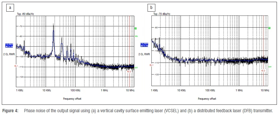
Figure 4a and 4b illustrates a sample of phase noise performance on VCSEL and DFB transmitters, respectively. The regions arise from different sources of laser noise contribution. Random noise predominates very close to the carrier frequency. Random noise is normally very difficult to measure because it is very close to the carrier. Flicker phase noise may be related to the physical resonance mechanism of an oscillator or the choice of parts used for the electronics design of the oscillator, but it is usually added by noisy electronics.10 The peaks on the noise floor between 10 kHz and 100 kHz in Figure 4a correspond to poor jitter performance on the VCSEL transmitter. Typically, a DFB transmitter bandwidth is about 2 MHz, while that of a VCSEL is about 10 MHz. This difference will cause the phase noise of the VCSEL to be higher than that of a DFB, which will dramatically degrade the system performance.
Appropriate modulation voltages were selected. The optimal RF power level was that required to modulate the laser such that optimal photodiode performance was achieved. The RF output from the various sources is shown in Figure 5a.
The directly modulated lasers show a higher output than that of the externally modulated source. This result is because of the power losses incurred in the external modulation. VCSEL is a low-power device, therefore the optical power range is lower than that of the RF fibre link laser and DFB lasers, and hence the RF output range is lower. The RF fibre link laser and VCSEL give a better RF output response as compared to both the DFB and WDM lasers.
The dotted line in Figure 5b shows the telescope expected jitter threshold of 130 fs. For all the measurements, proper choice of bias voltage and modulation powers were chosen so as to avoid distortions of the received clock signal. The nonlinear operation in electronics is responsible for signal distortions. Higher jitter values were obtained for VCSEL and WDM lasers than with DFB and RF fibre link lasers. VCSEL showed some small deviation over a range of optical power of -20 dBm to -7.5 dBm, but high jitter of about 1.8 ps. The WDM laser gave the highest jitter deviation, extending to about 14 ps at -22.5 dBm of optical power.
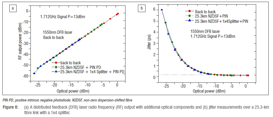
DFB and RF fibre link lasers meet the threshold but over different optical power ranges. The DFB laser has the best performance with jitter of less than 130 fs over a range of optical power of -15 dBm to about -3 dBm. The different performance of the various lasers may be attributed to differences in the structural designs, semiconductor material and operating specifications. From Figure 6a, it is noted that the fibre and a splitter reduce the power without altering the RF output trend. The modulation power was maintained at 13 dBm. From Figure 6b, it was established that no significant jitter alteration was contributed by the fibre spool and splitter. The additional passive components merely reduce the optical power without significantly degrading the phase noise. The 25.3-km fibre spool used is double the expected distance of the furthest MeerKAT dish from the Karoo Processor Building. This length is to demonstrate that the same optical transmitter can be employed in the round-trip monitoring while meeting the jitter requirements. Round-trip monitoring is not envisaged in the MeerKAT design, but the demonstration allows for a possible extension if need be. For a 12-km fibre link, more optical power will be available for splitting. With an optical power of about -12 dBm on the receiver, a 1x4 splitter can be employed in the link. This power level is sufficient for the 1.712-GHz clock to drive the digitiser without the need for an amplifier. This finding implies that one laser source can be utilised for four dishes. Therefore, only 16 lasers will be required to serve the 64 dishes, thus reducing the cost significantly.
Conclusion
Timing and synchronisation of the dishes is vital for the functioning of the radio telescope. We have experimentally demonstrated a 1.712-GHz clock transmission over 25 km of optical fibre. To enhance stability, MeerKAT's time and frequency reference system requires the proper choice of laser and appropriate modulation levels. A DFB optical transmitter attained a clock jitter of 130 fs for a 1.712-GHz clock. This laser is thus the preferred candidate that meets the expected performance requirements and link budget for the MeerKAT time and frequency reference system. Passive components reduce the optical power without causing jitter deterioration in the link.
Acknowledgements
We are grateful to Telkom, Dartcom, Ingoma, CSIR, CISCO, THRIP and SKA (NRF, South Africa), Nelson Mandela University and the University of Kabianga for support.
Authors' contributions
E.K.R.K. was the lead author; R.R.G.G., S.M. and H.K. collected the data and together with E.K.R.K. performed the experiments; A.W.R.L., T.B.G. and F.K. contributed to the project design and data analysis.
References
1. MeerKAT radio telescope [homepage on the Internet]. c2013 [cited 2016 Aug 09]. Available from: http://www.ska.ac.za/meerkat/
2. Peens-Hough A, Küsel T, Malan S, Kapp F, Esterhuyse W. MeerKAT system preliminary design memo series m0000-0000v1-42 tm revision 1a. 2012. Unpublished internal report. [ Links ]
3. Mullavey AJ, Slagmolen BJJ, Shaddock DA, McClelland DE. Stable transfer of an optical frequency standard via a 4.6 km optical fibre. Opt Exp. 2010;18(5):5213-5320. [ Links ]
4. Baldwin KG, He Y, Hsu M, Wouters M, Gray M, Orr BJ, et al. Analog and all-digital frequency distribution via optical fibre links. In: Proceedings of the Conference on Lasers and Electro-Optics (CLEO) Science and Innovations; 2012 May 6-11; San Jose, CA, USA. OSA Tech Dig. 2012, Art. #CTh4A.2. https://doi.org/10.1364/CLEO_SI.2012.CTh4A.2 [ Links ]
5. Durand S, Jackson J, Morris K. Phase coherence of the EVLA radio telescope. In: Stepp LM, editor. SPIE 6267: Ground-based and Airborne Telescopes; 2006 May 24; Orlando, FL, USA. SPIE; 2006. 62673Y. https://doi.org/10.1117/12.667804 [ Links ]
6. Shillue W. Fibre distribution of local oscillator for Atacama Large Millimetre Array. In: Proceedings of the Optical Fibre Communication/National Fibre Optic Engineers Conference; 2008 Feb 24-28; San Diego, CA, USA. IEEE; 2008. p.1-3. https://doi.org/10.1109/OFC.2008.4528513 [ Links ]
7. McCool R, Bentley M, Argo MK, Spencer R, Garrington S. Transfer of a 1486.3 MHz frequency standard over installed fibre links for local oscillator distribution with a stability of 1 picosecond. In: Proceedings of the European Conference on Optical Communication; 2008 Sep 21-25; Brussels, Belgium. IEEE; 2008. p. 1-2. https://doi.org/10.1109/ECOC.2008.4729488 [ Links ]
8. Gibbon TB, Rotich EK, Kourouma HYS, Gamatham RRG, Leitch AWR, Siebrits R, et al. 2013 Fibre-to-the-telescope: MeerKAT, the South African precursor to Square Kilometre Telescope Array (SKA). In: Weiershausen W, Dingel BB, Dutta AK, Srivastava AK, editors. Proceedings of SPIE 9008 Optical Metro Networks and Short-Haul Systems VI 90080P; 2014 Feb 01; San Francisco, CA, USA. SPIE; 2014. https://doi.org/10.1117/12.2049434 [ Links ]
9. Rotich Kipnoo EK, Kourouma HYS, Gamatham RR, Leitch AWR, Gibbon TB, Julie R, et al. Characterization of the polarization mode dispersion of single mode fibre in KAT-7 Telescope Array Network, South Africa. In: AFRICON; 2013 Sep 9-12; Pointe-Aux-Piments, Mauritius. IEEE; 2013. p. 1-4. https://doi.org/10.1109/AFRCON.2013.6757860 [ Links ]
10. Kester W. Converting oscillator phase noise to time jitter. MT-008 Tutorial. Norwood, MA: Analog Devices Inc.; 2009. Available from: http://www.analog.com/media/en/training-seminars/tutorials/MT-008.pdf. [ Links ]
 Correspondence:
Enoch Rotich Kipnoo
Enoch.Rotich@nmmu.ac.za
Received: 09 Aug. 2016
Revised: 06 Oct. 2016
Accepted: 14 Jan. 2017
FUNDING: Telkom; Dartcom; Ingoma; CSIR; CISCO; THRIP, SKA (National Research Foundation of South Africa); Nelson Mandela University; University of Kabianga

