


Services on Demand
Article
 English (pdf)
 Article in xml format
 Article references
Indicators

Related links
-
 Cited by Google
 -
 Similars in Google
Share

 Permalink
South African Journal of Science
On-line version ISSN 1996-7489
Print version ISSN 0038-2353
S. Afr. j. sci. vol.111 n.7-8 Pretoria Jul./Aug. 2015
http://dx.doi.org/10.17159/SAJS.2015/20140082
RESEARCH ARTICLE
A multiphysics simulation of a fluorine electrolysis cell
Ryno PretoriusI; Philippus L. CrouseI; Christiaan J. HattinghII
IDepartment of Chemical Engineering, University of Pretoria, Pretoria, South Africa
IIMetallurgical Testing and Consulting (MTC) cc, Benoni, South Africa
ABSTRACT
We modelled a laboratory-scale fluorine reactor which employed fully coupled, fundamental electron, heat, mass and momentum transfer (two-phase) equations to deliver a transient simulation. Hydrodynamic quasi-steady-state results were produced for the current density, electric field, temperature, reactive species concentration, gas and liquid velocity profiles as well as gas fraction distribution within the reactor. Simulation results were verified by modelling and comparing models from published works on similar reactors, as the laboratory-scale reactor is still in construction phase. Comparisons were favourable.
Keywords: fluorine reactor; two-phase simulation; comparative study; coupled transfer process
Introduction
Industrial manufacture of fluorine requires the extraction of hydrogen fluoride from fluorspar, the electrolysis of hydrogen fluoride to form fluorine gas, and, finally, purification by a separation step.1 Moissan was the first to produce fluorine gas via electrolysis.2 His original cell has been refined over the years, but the fundamental operating principles have not changed much.3
Very little is currently known, at least in the open literature, about the hydrodynamic behaviour of fluorine electrolysers. Experimental studies are difficult and dangerous, because they involve corrosive chemicals, at elevated temperatures, and high electric currents. A theoretical study was therefore commissioned to better understand typical cell operation. The hydrodynamic behaviour inside a typical two-electrode reactor was mathematically modelled using applicable computational fluid dynamics simulation software (COMSOL Multiphysics®). The reactor will be built and studied using recommendations found during the simulation procedure at a later date.
Fluorine electrolysis typically operates by subjecting molten potassium-acid-fluoride (KF.xHF, 1.8 ≤ x 2.2) to an electric field. The potassium-fluoride matrix is required because of the low electrical conductivity of anhydrous hydrogen fluoride. Hydrogen forms at the cathode and fluorine at the carbon anode. A separator skirt prevents explosive recombination of the gaseous components.4
Bubble formation severely complicates cell operation and is the major source of electrolyte flow caused by gaseous convection, which in turn causes mixing of the diluted reactant species. Furthermore the high electrical resistivity of the gaseous bubbles compared to the electrolyte results in several phenomena on the electrode.5 The anode is particularly susceptible to bubble phenomena as a consequence of the tendency of fluorine bubbles to stick to the electrode surface and move up slowly along the anode as a result of buoyancy forces.3
Thermodynamic hydrogen fluoride decomposition requires a potential of 2.9 V, but an anode-cathode voltage of 8-10 V is required to maintain a current density of 10-12 A/dm2 in industrial cells.6 The reversible cell voltage (ΦRV) or thermodynamic decomposition voltage is the minimum potential required for product formation during electrolysis. Any voltage supplied that surpasses the reversible voltage (done to achieve the desired current density) produces heat through Ohmic heating.3,7
As a consequence of the unavailability of experimental data at simulation completion, the modelling technique was evaluated through a comparison with published fluorine cell simulations. Published models8,9 were compared with self-produced simulacrums that we recreated under the same conditions. Further validation was received by comparing the results with other work published.10-12
Modelling procedure
Four coupled transfer processes were identified as critical to ensure an accurate model: electron, heat, mass and two-phase momentum transfer. Roustan and co-workers9 modelled uncoupled electron, heat and momentum transfer (single phase), using Flux-Expert®. They investigated the two-phase momentum transfer using Flux-Expert® and Ested Astrid code using predetermined experimental values for electron and heat transfer. We attempted to encompass all of the above-mentioned transfer processes into a single coupled model. Standard fundamental transfer equations were used where possible. Widely used empirical correlations were employed where fundamental equations were not available. A detailed description of the modelling procedure as well as the equations and variables used during modelling can be found in the Online Supplementary Material.
Because of the complex coupling (complete interdependence) between the featured transfer processes, a four-step solution method was employed. In the first step, the cell potential was slowly ramped up to its final value in a time-independent calculation. This value was then used as a starting value to do a time-dependent calculation to solve heat and momentum transfer. A third calculation was done in which transient mass transfer was calculated using the values calculated in the previous calculation as a starting value. Finally, all of the values calculated above were used to calculate the transient fully coupled electron, heat, mass and momentum transfer processes up to a point at which a hydrodynamic steady state was reached.
Two meshes were used to ensure a mesh-independent solution. The first was a very fine mesh used to calculate the first three iterations. The second mesh was as fine but utilised rectangular mesh elements in which complex variable interaction occurred. These rectangular mesh elements are extremely useful in situations in which a lot of change occurs in one direction, but very little in the perpendicular direction. The meshes were employed on the electrodes and separator skirt. Mesh-dependent solutions were further deterred by ensuring that the solutions converged to a common solution with mesh refinement.
Results and discussion
For the results shown, we assume a static homogeneous molten electrolyte at simulation initiation. Time-dependent results of interest and importance are shown at 100 s after simulation (and electrochemical reaction) commenced; this point in time was identified as a hydrodynamic steady state within the reactor.
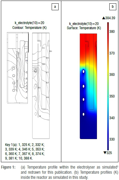
In general, arrows represented in the results indicate direction and are proportional to the norm of the vector quantity represented, at the arrow starting point. Colours indicate values as given by the legend to the right of the image.
Published result comparison
Simulation results were not justified with experimental data; instead it was decided to simulate published fluorine electrolysers while construction and commissioning of the lab-scale electrolyser was taking place. Roustan et al.'s9 publication was used, from which electron, heat and single-phase momentum transfer could be compared. All comparisons were favourable; one such comparison is shown in Figure 1.
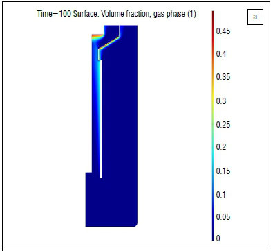
We used a two-phase momentum transfer equation; a suitable model comparison was therefore required and Roustan et al.'s9 was chosen. The two-phase momentum transfer results as found by Espinasse and co-workers8 is shown in Figure 2a. We found similar plume shapes (as shown in Figure 2b). The predicted gas fraction was, however, significantly lower, but supported by photographic evidence.7
Simulations
Our simulations were based on a simple lab-scale fluorine electrolyser comprised of one anode and a corresponding cathode. A cross section of the middle of the reactor was modelled and is shown in subsequent figures.
Momentum transfer
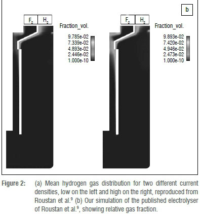
Figure 3 shows a well-developed hydrogen plume, and detachment from the cathode occurs as expected. Very little hydrogen migration into the fluorine section is observed; therefore the chance of explosive recombination of product gases is very low. This finding is also good from a productivity standpoint, as fewer product gases are lost and less purification of product streams will be required.
The electrolyte movement (Figure 4) induced by gaseous (hydrogen) movement is evidenced by the swirling liquid phase eddy between the separator skirt and the cathode at the top right of the reactor. This same eddy has the effect of causing convective stirring throughout the reactor, increasing heat and mass transfer (which in turn increases current density and reaction rate). These observations align well with what is observed in industrial and other lab-scale reactors.

Electron transfer
Figure 5 shows the electric potential and electric potential contour lines within the electrolyte. Electric potential drops from the anode to the cathode, from 9.1 V to 0 V, as expected. This result corresponds to the potential change expected from the literature. The bending of the electric potential contour lines along the separator skirt corresponds to the electric current density field lines that bend around the skirt. Boundary effects such as bubbles cause a large electrical conductivity decrease, as a result of the low conductivity of the gaseous phase, resulting in an exponential potential drop over these bubbles on the boundaries.

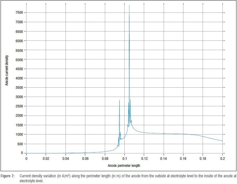
Current density distribution and electric field lines within the cell are shown in Figure 6. Current density values are high at the sharp tips of the electrodes because of the small available surface area. High current density values are also visible along the separator skirt because the charged ions flow around this point to travel between electrodes.
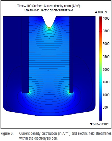
This point is further illustrated when looking at one-dimensional current density distribution along the length of the anode, as shown in Figure 7. The points of high current density are major heat sources during electrolysis.
Heat transfer
From the internal temperature distribution results it was found that heat flux followed the same path as the electrolyte convection path shown in Figure 4. This shows that heat convection is the dominant heat flux component that removes heat from the electrode tips and separation skirt and transfers the heat to the cooled reactor wall. A parametric study was done on the value of electrolyte thermal conductivity as it is not widely available. It was found that a thermal conductivity value of 1.25 W/(m.K) (the thermal conductivity of potassium fluoride) was more than sufficient because heat conduction is completely overshadowed by heat convection during operation. In the interests of brevity and space, heat transfer images are not shown here.
Mass transfer
HF is produced at the anode and consumed at the cathode. The concentration gradient as a result of consumption at the cathode is a contributor to flux in the form of diffusion. From the scale bar on the right, it is clear that more HF is consumed than produced, as was predicted by the electrode half reactions (Equations 10 and 11 in the Online Supplementary Material). From Figure 8, it is evident that the secondary contributors to flux are convection and migration due to electrical field.
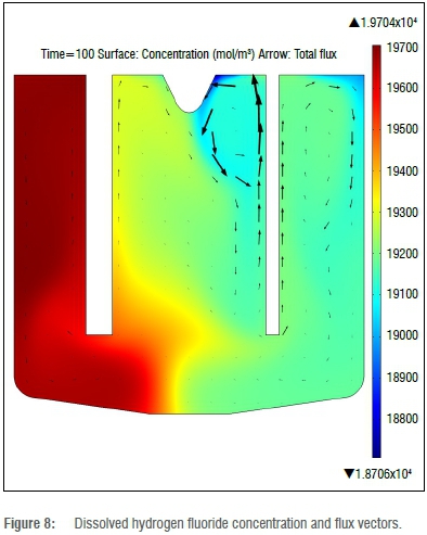
The ion flux and concentration of HF2- is not shown, but is a mirror image of Figure 8. The HF2- ion is produced at the cathode and consumed at the anode. The concentration gradient indicates ion flux from the cathode to the anode, as expected.
Conclusions and recommendations
Results obtained from the simulations, under the quasi-steady-state assumption, are reasonable and within expectations. The simulated results show a strong correlation between the gaseous phase movement (induced by buoyancy forces) and that of the liquid phase. The gas-phase flux seen in Figure 3 shows that little or no hydrogen gas transfers to the fluorine compartment. All comparative simulations also deliver satisfactory results when compared with the published works. Current density and electric potential field line predictions correspond to expectations and match up satisfactorily with those found by Espinasse et al.8 The shape of the gaseous plume of hydrogen that forms at the anode is the same as that reported in the literature when compared to the results from Mandin et al.5 and Roustan et al.9 There is, however, a difference in the qualitative gaseous fraction of the published and simulated reactors.
It is therefore recommended that the results found be used by the construction and experimental team of the physical reactor as an indication of what to expect and what to investigate. We also recommend that the physical parameters (mostly estimates) and empirical correlations, specifically the kinetics, be investigated to deliver more accurate results in future simulations.
Authors' contributions
P.L.C. was the project supervisor and academic lead at the University of Pretoria. R.P. was responsible for project design, relevant research and most of the simulation work. R.P. also presented the findings of this paper at a conference in Stuttgart, Germany. C.J.H. aided in the simulation, especially in solution finding and mathematical convergence.
References
1. Klose F. Elements and compounds, atoms and molecules, structures and bonds - Course on inorganic chemistry for the University of Magdeburg. Magdeburg: University of Magdeburg; 2004. [ Links ]
2. Groult H, Lantelme F Salanne M, Simon C, Belhomme C, Morel B, et al. Role of elemental fluorine in nuclear field. J Fluor Chem. 2007;128:285-295. http://dx.doi.org/10.1016/j.jfluchem.2006.11.012 [ Links ]
3. Rudge AJ. Production of elemental fluorine by electrolysis. In: Kuhn A, editor. Industrial electrochemical processes. Amsterdam: Elsevier; 1971. p. 1-78. [ Links ]
4. Shia G. Fluorine. In: Arza S, editor. Kirk-Othmer encyclopedia of chemical technology. 14th ed. New Jersey: John Wiley & Sons; 2005. p. 826-852. [ Links ]
5. Mandin Ph, Wuthrich R, Roustan H. Electrochemical engineering modelling of the electrodes kinetic properties during two-phase sustainable electrolysis. Paper presented at: 10th International Symposium on Process Systems Engineering; 2009 Aug 16-20; Salvador-Bahia, Brazil. [ Links ]
6. Groult H. Electrochemistry of fluorine production. J Fluor Chem. 2003;119:173-189. http://dx.doi.org/10.1016/S0022-1139(02)00252-X [ Links ]
7. Heitz E, Kreysa G. Principles of electrochemical engineering. Weinheim: VCH Verslasgesellschaft mbH; 1986. [ Links ]
8. Espinasse G, Peyrard M, Nicolas F, Caire JP Effects of hydrodynamics on Faradaic current efficiency in a fluorine electrolyser. J Appl Electrochem. 2007;37:77-85. http://dx.doi.org/10.1007/s10800-006-9216-x [ Links ]
9. Roustan H, Caire JP, Nicolas, F, Pham P. Modelling coupled transfers in an industrial fluorine electrolyser. J Appl Electrochem. 1997;28:237-243. http://dx.doi.org/10.1023/A:1003299213119 [ Links ]
10. Hur JS, Shin CB, Kim H, Kwonb YS. Modeling of the trajectories of the hydrogen bubbles in a fluorine production cell. J Electrochem Soc. 2003;150(3):D70-D78. [ Links ]
11. Newman JS. Electrochemical systems. New Jersey: Prentice Hall; 1991. [ Links ]
12. Nierhaus T. Two-phase flow transport phenomena in electrochemical processes [PhD thesis]. Brussels: Vrije Universiteit Brussel; 2009. [ Links ]
 Correspondence:
Ryno Pretorius
Department of Chemical
Engineering, University of Pretoria
Private Bag X20, Hatfield 0028
South Africa
Email: Rpretorius.chemeng@gmail.com
Received: 05 Mar. 2014
Revised: 16 July 2014
Accepted: 21 Sep. 2014

