


Servicios Personalizados
Articulo
 Inglés (pdf)
 Articulo en XML
 Referencias del artículo
Indicadores

Links relacionados
-
 Citado por Google
 -
 Similares en Google
Compartir

 Permalink
South African Journal of Science
versión On-line ISSN 1996-7489
versión impresa ISSN 0038-2353
S. Afr. j. sci. vol.111 no.3-4 Pretoria mar./abr. 2015
http://dx.doi.org/10.17159/sajs.2015/20130262
RESEARCH ARTICLE
Preliminary laboratory assessments of a lightweight geocomposite material for embankment fill application
Felix Okonta
Civil Engineering Science, University of Johannesburg, Johannesburg, South Africa
ABSTRACT
The cost of retaining structures used for the lateral support of roadside embankments can be significantly reduced through the use of lightly cemented mixtures of expanded polystyrene (EPS) beads and backfill soils as lightweight roadside embankment material. Four grades of residually derived sandy soils were mixed with EPS beads and the geocomposites were stabilised with 3% cement content, compacted and cured. The textural properties and shear strength parameters of dry and soaked specimens of the cemented geocomposites were determined by direct shear tests. The shear parameters and slope stability charts were used to simulate the slope of typical road embankments. The settlement potentials at different applied normal stresses were also determined. Inclusion of EPS reduced the dry density of the residual soils from an average value of 1790 kg/m3 to 1335 kg/m3. The maximum friction coefficient, tan Ø', mobilised by the geocomposite specimens decreased with an increase in the soil fines content (>0.425 mm). The difference in tan Ø' between the stabilised geocomposites and the natural soil was also dependent on the fines content. For an embankment height of 20 m, slope angles of 38° and 62° were determined for fine sand geocomposites in fully saturated drainage and drained conditions, respectively. Lower slope angles were determined for geocomposites made from silty, coarse and gravelly sands. A limiting embankment height of 50 m was determined for the four geocomposites. Rainfall-induced settlement of geocomposites was dependent on pre-inundation stiffness; for the range of applied stress up to 200 kPa, the settlement exhibited by the fine and silty sand geocomposites was lower than that for the coarse and gravelly sand geocomposites. Fine and silty sands make poor materials for slope embankments because of their poor hydraulic conductivity; however, fine and silty sand geocomposites have a good conductivity and friction angle to support slope embankments.
Keywords: backfills; expanded polystyrene; friction coefficient; texture; shear strength
Introduction
The cost of road construction can be reduced significantly when the backfill materials used for the preparation of the road subgrade, subbase and side embankments are constructed using soil and road materials that exist along the designated roadway. In most parts of the tropical and subtropical regions of the world, residual soils are frequently encountered along most proposed roadways. Because of the mode of formation, residual soils are heterogeneous and may be predominantly granular or very fine depending on the degree of weathering. The texture and mechanical properties of the soil may vary both laterally and vertically. It may be difficult to predict the type of foundation required when a residual soil is encountered.1,2 Residual soils can be recompacted to high density in situ, and are known to mobilise high shear strength when dried, but can soften significantly when wet or poorly drained. Thus embankments constructed with residual soils often require cement stabilisation and a retaining structure to limit or prevent roadside embankment slope failure, especially upon inundation.
Zeevert1 noted that the granulometry of residual materials can be very variable and may consist of clay and colloids, silt, sand or gravel. This variability means that the density and cementation of the soil can also vary widely. In the upper part of the soil, compressibility may be high and shear strength very low. Earth works requiring compaction of backfills and road embankments are expensive programmes. Poorly compacted residual soils often exhibit significant collapse settlement as a result of rainfall and low undrained shear strength caused by poor and remoulded drainage profiles.3 Thus the stability of embankments in residual formations requires detailed parametric analysis.
The use of retaining walls to prevent roadside slope failure can be very expensive and for low-cost roads may not be easily justifiable. The use of lightweight geocomposite materials stabilised with lean cement content may offer a cost-effective option for road embankment construction. Roadside embankment infrastructures like bridge abutments, roadside embankments and retaining wall backfills built up with normal residual backfill may require extra embedment depth and adequate reinforcements to prevent lateral displacement and cracking of the retaining wall. The failure of such infrastructures can be prevented through the use of a lightweight fill as an alternative geometrical for the relief of the overburden mass and lateral load of the conventional, but massive, earth filling materials.
Literature review
Polystyrene is a synthetic material produced from naphtha, a by-product of the refining process of petroleum. Heat-induced expansion of pentene gas infused in polystyrene results in expanded polystyrene (EPS) materials in the form of beads or blocks. Polystyrene is a relatively cheap material and widely available. It is durable in harsh environments and often outlives the life expectancy of conventional construction materials. It is commonly used for pipe insulation, lightweight fill material, sheet wall insulation, concrete moulds and backfill insulation.4,5 The effect of small polystyrene blocks on the mechanical properties of retaining wall backfill has been investigated.5 Layers of polystyrene blocks were placed above the granular backfill behind a stretch of a retaining wall.5 The inclusion of polystyrene blocks decreased the lateral pressure on the retaining wall to such an extent that it was possible to decrease the quantity of reinforcing required in the retaining wall and effectively save costs. Polystyrene has also been used to reduce the settlement of the backfills and increase their insulation. Polystyrene fill was used for the extension of Highway Bridge in Salt Lake City - an area underlain by alluvium deposits of soft clay and lacustrine silt. Geoforms made up of EPS blocks were applied to mitigate settlement of the bridge approach embankments that were constructed over the compressible soft soils.6 EPS blocks are not suitable for construction in confined spaces and inaccessible locations because of their shape; the blocks are limited to regular shapes and cannot readily be used in areas with irregular shape.7
Extensive investigations have been done on the use of lightweight fill material for the construction of embankments on sandy soils, weak soils and dredged mud. Lightweight materials for embankments were achieved by mixing EPS beads, polystyrene pre-puff beads, soil materials, water and cement. Lightweight fill materials made with polystyrene beads were found to be more expensive when cement was used as extra manpower or machines were often required for cement mixing.7-10
Onishi et al.11 investigated the strength and small strain modulus of cement stabilised sand mixed with EPS beads, which they referred to as cemented sand composite. It was found that the inclusion of the EPS beads degraded the strength and deformation properties of the geomaterial even when cement was used; however, when cement was used in appropriate amounts, the strength and deformation properties of the sand composites were enhanced. As a granular material, the shear behaviour of sand-EPS lightweight fills plays an important role in deformation and stability in practical works, and thus deserves further investigation beyond its general engineering properties. The shear behaviour of the two-phase (sand-EPS) geomaterial composite is more complicated than that of common geomaterials composed of pure soils and rocks. The behaviour is essentially dependent on the mix ratios and mechanical interaction of sands and beads.12 The reduction of lateral earth forces acting on non-yielding retaining walls by EPS inclusion was also investigated.13 It was observed that the deformation of the EPS was concentrated in the bottom half of the retaining wall because of higher stresses in that zone. The elastic and plastic deformation phases of EPS-based backfill make the prediction of field settlement a design challenge, as elastic and plastic deformation parameters depended on the external load, loading rate and field drainage paths.
Shear-induced deformation parameters of naturally cemented and lightly cemented soft soils containing EPS were determined in the laboratory from the conventional constant normal stress triaxial or direct shear tests. The test condition in the triaxial apparatus assumes that the external load on the sample remains constant until failure and the shear strength mobilised is associated with shear-induced volume compression or dilation of the material. In reality, for most insitu loading conditions, the principal stresses rotate during shear and are not constant as in triaxial devices. Furthermore, back analysis of slope failures shows close correlation with shear strength parameters derived from the direct shear tests. The aim of this research was to evaluate the shear parameters of a lightly cemented mixture of EPS and granular soil materials (cemented composites), to determine the relationship between the textural properties of soil backfill materials and the strength properties of the geocomposites, and to estimate the slope angles of typical embankments of the cemented composites for different drainage conditions and the moisture-induced settlement potential of the cemented composites.
Materials and methods
Materials
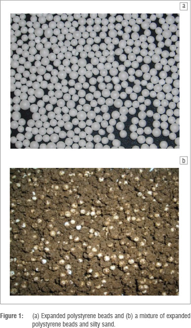
The EPS investigated (shown in Figure 1) was collected from a textile factory in Johannesburg, at which the beads were further processed and used for the production of picture frames and furniture. The beads were spherical to near spherical superlight polymer products of pre-puffed polymer resins. The material was kept in a dry chamber before use.
The residual soil used is a common backfilling material derived from the weathering of quartzite. Reddish residual sandy soil was obtained from a road construction site in Auckland Park, Johannesburg. The Brixton Formation is part of the West Rand Group which forms part of the Witwatersrand Supergroup. The Witwatersrand Supergroup is made up of a thick sequence of shales, quartzites and conglomerates.14 X-ray diffractometer analysis of the mineral constitution revealed the presence of quartz, haematite, muscovite, garronite and chloritoid. Quartz was the greatest constituent of the soil, followed by haematite, muscovite, garronite and chloritoid. The residual soil was dried, mixed and sieved to remove soil fractions with diameters greater than 6.75 mm. The soil was then reconstituted to produce the following four major types of backfills: silty sands (0.075-4.75 mm; 30% <0.075 mm), fine sands (0.0754.75 mm; 10% <0.075 mm), uniform coarse sands (2.00-4.75 mm) and gravelly sands (0.075-6.75 mm; 70% <4.75 mm). Although the particle size diameter of the EPS is within the range of 2.35-6.75 mm, only the fraction with diameters in the range 2.35-4.75 mm was used. The four backfill materials were compacted in a mould by the application of 55 blows per layer to three layers of each material in a mould 150 mm in diameter and 125 mm in height, in order to determine the maximum dry density and optimum moisture content. Mixtures of backfill materials and 3% cement by mass were made and transferred into a large graduated cylinder. The mixture was blended with 30% by volume of EPS beads and water and also compacted in the mould to determine the effect of EPS proportion on the optimum moisture content and dry density of cement-stabilised backfill materials.
An ordinary Portland cement (CEM II, Afrisam, Johannesburg, South Africa) was used as a binder. The specific gravity of the cement was 3.6 g/cm3. The compressive strength of the mortar was 22 MPa after 3 days and 30 MPa after 7 days. To provide adequate bonding for the composite material, 3% of the cement by mass of the backfill was used. For the stabilisation of poor road subgrade and the backfill layer below the subbase, the amount of cement used often varies from 1% to 3%, especially for C4 grade roads. This amount of cement is usually adequate to provide strength improvement in residual soils. A value of 3% was adopted after preliminary tests indicated that 2% and 3% cement showed some sensitivity to moisture-induced reduction in strength of residual soil based lightweight geocomposite. In addition, the treatment of roadside embankments with a high percentage of cement would result in a very high total road construction cost, especially for low-cost or low-grade roads in undulating terrain. The optimum moisture content and dry density of the cement-stabilised EPS-backfill specimens were used to prepare the specimens for shear strength tests.
The four composite materials produced were: (1) a cement-stabilised mixture of EPS and silty sand, (2) a cement-stabilised mixture of EPS and fine sand, (3) a cement-stabilised mixture of EPS and uniform sand and (4) a cement-stabilised mixture of EPS and gravelly sand.
Direct shear test
For the direct shear tests, compacted specimens of the natural soils and the geocomposite materials were cut into 100-mm square specimens with a thickness of 50 mm. The direct shear specimens were soaked for 6 days in a curing room at a constant humidity of 80% and temperature of 20 °C to ensure that sufficient water was available for cement hydrolysis. On the seventh day, a set of the soaked specimens was further soaked for 24 days in the shear box and tested. A second set of specimens was dried to the optimum moisture content and tested. The constant normal stress direct shear tests were conducted in a 100-mm square shear box apparatus with a lever arch loading system. The specimens were consolidated with applied normal stresses of 50 kPa, 100 kPa, 200 kPa and 400 kPa. The samples were then sheared at a shear displacement rate of 0.2 mm/min.
Settlement test
There are two widely used laboratory methods for determining the collapse settlement of soils. The first is the double oedometer collapse settlement method in which one of two identical samples is saturated before subjecting both samples to a series of applied stresses. Moisture-induced collapse settlement of the cemented composites was studied by the second method. This method entails increasing the stress on a sample up to a specified value followed by inundation at that specified stress. The advantage of the second method of determining collapse settlement is that field compression stress paths can be directly simulated.
The samples used for these tests were statically compacted into standard oedometer rings 40 mm in height and 150 mm in diameter at an initial moisture content of 20%, and placed in the oedometer pots between air-dried porous stones. The inner surface of the oedometer rings was lubricated with a commonly available spray lubricant (Q10) before sample compaction to reduce the effect of side shear in the sample during compression. All the samples used for the standard settlement tests and moisture-induced collapse settlement tests were left for 24 h for consolidation. Depending on the tests, at a given applied stress, collapse was induced by gradually filling the oedometer pots with distilled water, after removing the plastic bag. The sample was then allowed to stand for 24 h after which time the deflection was noted.
At a given vertical stress, the samples were soaked by gradually filling the oedometer pots with distilled water, thus ensuring that moisture uptake was through suction alone, and the amount of collapse was noted. Moisture-induced settlement was calculated as the ratio of the change in height, ΔH, of a specimen when soaked to the initial height H associated with the soaking pressure, expressed as a percentage.
The moisture-induced settlement of a specimen at any applied stress expressed as a percentage was given by Knight15 as:
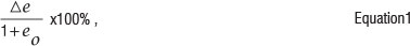
where Δe is the change in void ratios as a result of saturation and eo is the void ratio of the sample before inundation. Because of the difficulty in estimating the void ratio of the cemented geocomposite materials, the general form of Equation 1 - that which is applicable to one-dimensional compression and settlement relationships - is used.
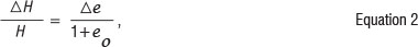
where ΔH represents the change in height of a specimen as a result of saturation and H is the height of the specimen as a result of the current applied stress before inundation. One-dimensional compression tests were conducted on compacted specimens of homogenously blended EPS beads, residual soils and 3% cement. The mixture was blended with water equal to the optimum moisture content of the soil and was compacted into oedometer rings at maximum dry densities and cured for 7 days. The specimens were consolidated with applied normal stresses of 50 kPa, 100 kPa, 200 kPa and 400 kPa and soaked at selected applied normal stresses. After soaking, the specimens were left for 24 h before dial gauge reading and unloading.
Results and discussion
Textural properties
The textural properties of the backfill soils were determined from the particle size distribution curves shown in Figure 2. The major textural properties of the granular backfill (i.e. the per cent fines; >0.425 mm), the particle sizes that permit 10%, 30%, 50% and 60% of the granular backfill materials, the coefficient of uniformity (Cd) and the coefficient of curvature (Cc) are presented in Table 1. It can be noted that a well-graded soil has a uniformity coefficient of greater than 4 for gravel and 6 for sands, and a coefficient of curvature or gradation between 1 and 3.16
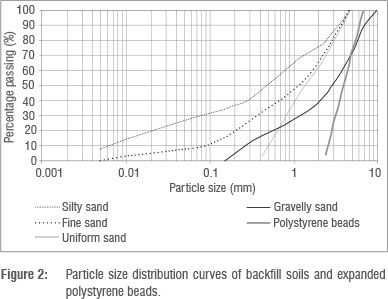
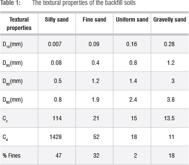
Values outside the stipulated ranges indicate a poorly graded soil. Poorly graded soils are gap graded because of the absence of soils of some particle sizes. The particle size range of the EPS beads is 2.3 mm to 4.74 mm and thus the beads are uniformly graded. The specific gravity and dry density are 0.021 and 21.097 kg/m3.
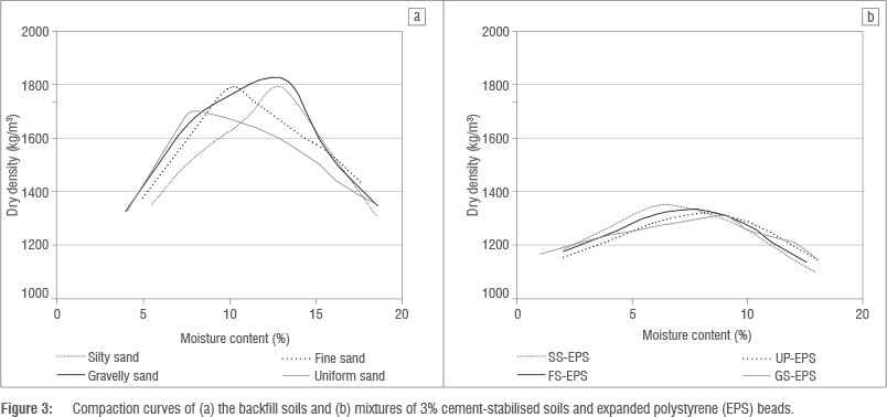
Compaction
The maximum density of the backfill soils ranged from 1730 kg/m3 to 1850 kg/m3 and the optimum moisture content ranged from 9% to 13%. The maximum densities of gravelly sand and silty sand are the maximum and minimum, respectively, and a trend of increasing dry density with an increase in the value of the textural properties was evident. These densities are above the 1650 kg/m3 benchmark of in-situ residual soils from southern Africa that have a high likelihood of moisture-induced settlement.14,15
The effect of the addition of 30% EPS (by volume) resulted in a decrease in the maximum dry density of the cement-stabilised soils (Figure 3a and 3b). The maximum density and optimum moisture content of the blended specimens of soil, EPS and 3% cement varied from 1303 kg/m3 to 1368kg/m3 and 9% to 7%, respectively. However, a trend of increasing dry density with the textural properties was not evident in Figure 3b.
Strength and deformation of silty sand geocomposite
The result of direct shear tests on the cement-stabilised mixture of fine sand and EPS is shown in Figure 4a. The specimens were tested after drying. The shear stress curves were presented in terms of stress ratio, i.e. the ratio of mobilised shear stress to the applied normal stress, because the stress ratio presented a better indication of the influence of applied stress on the slope of the stress-displacement curves at small shear displacements. The stress ratio is a good indicator of soil structure. The effect of an applied pressure of 50 kPa on the slope of the stress-displacement curve of the silty sand composite was minimal in comparison to the effect of higher applied stresses (100 kPa to 400 kPa) on the specimen. Thus the stress ratio mobilised by the specimen as a result of an applied stress of 50 kPa was the highest because the specimen structure was least degraded by the applied pressure of 50 kPa. For the range of applied stress used, the specimen exhibited strain-hardening behaviour, i.e. shear stress increased progressively with shear displacement, as a result of the increase in shear-induced volume compression of the specimen. The degree of strain hardening decreased with an increase in the magnitude of applied stress and the elastic, yield and plastic phases were more evident at low normal stress. The slope of the stress displacement curves was highest for a specimen subjected to a normal stress of 50 kPa. The displacements at which the maximum shear strength was mobilised increased with the applied pressure. The shear-induced volume compression also increased with the applied stress. At large imposed shear displacements there was coinciding shear stress and shear-induced volume compression, as both parameters tend to constant values and the shear stresses mobilised at large displacement varied in relation to applied pressure.
The strength envelope of soil and rock materials is the Mohr Coulomb failure criterion given by Equation 3:

where τ is the shear strength from drained tests, σn' is the effective normal stress, tan ta' is the coefficient of intergranular friction from drained tests and c' is the effective cohesion from drained tests.
The underlying concept of rupture mechanics contends that materials fail because off a critical combination of normal stress and shearing stresses and not from the maximum normal or shear stress alone. Thus the failure plane that defines the functional relationship between normal stress and shear stress is a curved line. For most soil mechanics problems, however, it is sufficient to express the shear stress as a linear function.16 The stress-deformation curves of soaked specimens are shown in Figure 4b. The specimens showed elastic plastic strain hardening behaviour -i.e. the stress ratio increased as a result of shear-induced compression of the specimens and the yield phase was not evident. The mobilised stress ratio and stiffness decreased with an increase in applied pressure while the magnitude of shear-induced volume compression increased with applied pressure. The percentage of fines (>0.425 mm) in the fine sand is 30%. The low shear strength mobilised by soaked specimens of fine sand as well as the direct shear-induced volume compression indicated in Figure 4c can be associated with the dry density and the percentage of fines.
Stress and deformation behaviour of cement-stabilised soils and EPS
The direct shear stress and deformation behaviour of dry and soaked specimens of cement-stabilised geocomposites made from fine sand, uniform coarse sand and gravelly soils and EPS are similar to the behaviour presented in Figure 4a and 4b. The dry specimens showed mild strain-hardening behaviour at low values of applied pressures and mild strain-hardening behaviour at large applied pressures. The transition from strain-hardening to strain-softening behaviour was associated with minimum shear-induced volume compression and higher stiffness of the specimen caused by low applied pressure and significant specimen compression at large applied pressure. Specimens subjected to low pressures also exhibited dilatancy at small displacement and compression at large imposed shear displacement. The dry specimens exhibited mild strain-softening behaviour characterised by elastic, yield and plastic phases of deformations at applied normal stress of 50 kPa and 100 kPa and elastic perfect plastic behaviour for applied normal stresses of 200 kPa and 400 kPa. At large imposed shear displacement, the mobilised shear stress and stress ratio decreased with an increase in applied normal stress. The weak cement bond was not broken down by the application of normal stresses of 50 kPa and 100 kPa and thus mobilised a high shear stress ratio at small displacement. At larger imposed displacement, the cement bond was gradually broken and plastic flow behaviour was exhibited. The application of normal stresses of 200 kPa and 400 kPa resulted in the breakdown of the cement bond and thus subsequent imposition of shear displacement resulted in elastic plastic behaviour and shear-induced volume compression. The displacements at which the maximum shear strength was mobilised varied and increased with the applied normal stress. The shear induced-volume compression also increased with the applied stress. The stress ratio curves of the soaked specimens were characterised by elastic plastic strain-hardening behaviour at applied pressures of 200 kPa and 400 kPa and strain-softening behaviour at applied pressures of 50 kPa and 100 kPa. The transition from strain softening to strain hardening was related to the influence of applied normal stress on specimen stiffness.
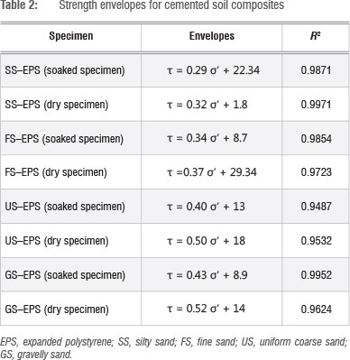
Strength envelopes of lightweight backfill materials
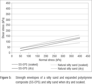
The strength envelopes for specimens of dry and soaked silty sand and specimens of a cement-stabilised mixture of silty sand and EPS are shown in Figure 5. The direct shear strength envelopes of the cemented geocomposites are also presented in Table 2. The shear strength of the cement-stabilised silty sand composite in the dry state was lower than that in the wet state for applied normal stress because of the effect of increased shear-induced compression in the soaked state on strain hardening, especially at large shear displacement. As the applied stress increases, the strength in the dry state approached the strength in the wet state because of an increase in intergranular friction. For the gravelly sand geocomposite, while the friction coefficient decreased by 50% as a result of inundation, the cohesion was only marginally affected by soaking. Figure 5 shows that the reduction in the mobilised friction coefficient from soaking increased with applied stress because of the combined effect of moisture-induced softening and reduction in stiffness and breakdown of the cement bond. The coupled effect of reduction in stiffness and breakdown of natural cement bonds is common in weathered residual rocks.17 There is no difference in the cohesion of dry silty sand and silty sand geocomposite; the difference in friction coefficient was due to the effect of increased normal stress on the structure of the natural soil and the stabilised geocomposite. The strengths of the residual silty sand specimens are very sensitive to changes in moisture content. The addition of cement reduced moisture sensitivity in the stabilised geocomposite.
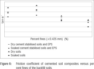
The effect of fines content of the backfill soils on the friction coefficient of the dry and soaked cemented soil composites is shown in Figure 6. The limiting fine content beyond which reduction of friction ceofficient sets in is approximately 20% and increasing the fines content to greater than 20% results in significant reduction in the friction coefficent of both the natural residual soils and the cement-stabilised geocomposites. The soils used for this investigation were low plasticity weathered quartzites and thus the fines specification also applied with the provision that the soils must be of low plasticity. The reduction in the friction coefficient of the cemented composites also decreased with increasing fines content and the relationship between moisture-induced percentage reduction in friction coefficient and fines content is exponential. Figure 6 also revealed that for the production of lightweight cemented soil and EPS, the backfill soils with intermediate fine content of 20% ensured that the composite material mobilised maximum friction coefficient and marginal reduction of friction coefficient upon inundation. In comparison with the natural soils, the mobilised friction coefficients of the geocomposites were lower, especially for fines contents lower than 20%; however, the dry densities of the geocomposites were lower by an average of 20%.
Simulated slope stability analysis
Taylor's stability charts derived from the friction circle method have been used for the stability analysis of clay pit slopes, projected open pit slopes for crushed waste rock mass, mining and construction waste dumps, and highly altered and weathered rocks based on limit equilibrium conditions. For such materials, failure may occur along a surface which approaches a circular shape. The general structure of lightly cemented soils and EPS beads falls under this category. Hoek and Bray17 modified the Taylor stability charts for cases of different drainage conditions. The general formulations are based on the shear strength parameters and factor of safety. Simulated limit equilibrium stability analysis was used to evaluate the stability of a typical embankment.
The factor of safety against failure (F) of a drained slope embankment of density (y), with slope angle (ψ ) and slope height (H), was expressed by Hoek and Bray17 as:

F is generally defined as the ratio of the shear strength for sliding resistance to shear strength mobilised by the material along the failure surface.
For an embankment constructed with granular backfill soil without cohesion, F is equal to [(tan  ')/(tan ψ)], i.e. F is independent of the height of the embankment and the slope of the embankment is stable as long as ψ < . If the shear strength of the backfill soil is based on both cohesion and frictional resistance, i.e. a cemented composite, the depth of the plane that is subject to critical equilibrium (or impending failure, F=1) is expresed by Equation 5:

For the condition of steady-stage seepage, i.e. the occurrence of seepage through the embankment material and when the groundwater level coincides with the slope surface:
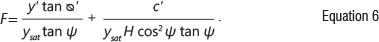
Hoek and Bray17 also reformulated Equations 4-6 into charts with dimensionless stability factors:
as the three axes of the charts. The charts were developed for different drainage conditions. The strength parameters presented in Table 2 were used to determine the stability factors. These charts were used to simulate the slope angles for selected embankment heights (0-100 m) for the different cemented composite specimens based on a factor of safety (F) of 1. The two groundwater conditions considered were: (1) a fully drained slope profile and (2) a saturated slope subject to heavy surface recharge (flooding). For a typical embankment of the geocomposites, the relationship between the slope angle (ψ) and slope height (H) was estimated from charts corresponding to the dry slope profile and a slope with a shallow water table. The slope height versus slope angle relationships which were based on the shear strength parameters of the lightweight fine sand composites in fully drained and fully saturated conditions are shown in Figure 7.
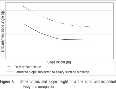
The slope stability charts were not sensitive to slope heights greater than 50 m, thus the limiting or critical slope of a lightweight embankment constructed with cement-stabilised soils and EPS is 50 m. For slope heights from 0 m to 50 m, the most suitable soils for the construction of an embankment slope are uniform coarse sands while the gravelly sand is the least stable material. Thus although the shear strength of the cemented gravelly sand geocomposites for the range of applied normal stresses was the highest, the simulated stability analysis of lightweight embankments constructed with the different soils revealed that for a typical slope height of 20 m, embankments built with fine sands geocomposite sustained slope angles of 65° and 44° in fully drained and saturated drainage conditions, respectively. For the same slope height, silty sand, uniform sand and gravelly sand geocomposites, respectively, sustained slopes of 58° and 40°, 62° and 41°, and 60° and 38° in fully drained and fully saturated conditions, respectively. The percentage reduction in slope angles as a result of the change in drainage conditions from drained to saturated conditions of the four geocomposites also increased with the embankment slope heights. The soil type that resulted in the least or maximum reduction in the slope angle of the composites was not clearly evident.
Moisture-induced settlement of cemented lightweight composites
Different mechanisms of moisture-induced collapse of soil deposits and compacted backfills have been postulated on the basis of soil structural matrix, initial stress state and parametric stress variables. It was postulated that the collapse of a soil structure is a result of a moisture-induced reduction in the strength of clay bridges existing between unweathered discrete grains in an open soil structure below existing applied stress.15 The reduction in strength is strongly related to the relative abundance of the different pore sizes within a soil matrix.18-20 Moisture-induced soil settlement potential criteria established for southern African formations recommended that about 80% of aeolian sands with dry densities greater than 1670 kg/m3 and mixed origin soils with dry densities greater than 1650 kg/m3 are generally not collapsible.21,22 While failure of roads, embankments and slopes that can be directly linked to rainfall-induced soil collapse are widespread in semi-arid regions of southern African and arid regions of the world, as noted by Paige Green and Gerryt (1998), the collapse of lightweight geocomposites consisting of lightly cemented soil and EPS are not widely documented. The collapse potential of specimens of cemented soils and EPS was evaluated using the severity of soil collapse proposed by Fookes23. The criteria related the percentage moisture-induced settlement of soil profile to the severity of the problem within the overlying infrastructure as follows: 0-1% (no problem), 1-5% (moderate trouble), 5-10% (severe trouble), 10-20% (severe to very severe trouble) and <20% (very severe trouble). Ratings from 10% and above can result in failure of the overlying infrastructure while ratings from 1% to 10% can result in tensile cracks induced by differential settlement of the foundation of the infrastructure as a result of moisture-induced collapse of the underlying soil.
Figure 8a and 8b show the effect of applied stress on the vertical strain of a silty sand geocomposite and the settlement potential curves of specimens of cemented silty sand and cemented gravelly sand composites. The magnitude of moisture-induced settlement of specimens of cemented silty and fine sand composites increased with the applied stress while the settlement of specimens of coarse and gravelly sand composites approached maximum values of settlement for an applied stress of 200 kPa and decreased at higher applied stress.
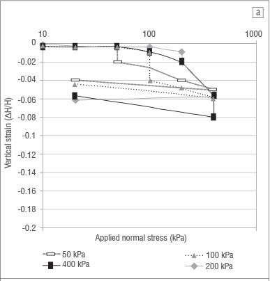
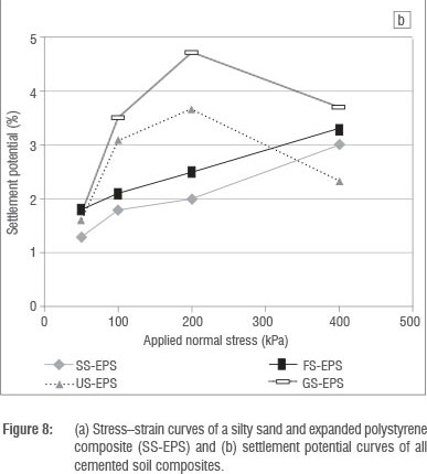
The moisture-induced settlement potential was dependent on the effect of applied normal pressure on the pre-inundation specimen stiffness. The specimen pre-inundation stiffness, also known as constrained modulus, is the ratio of the applied normal stress to the induced vertical strain before inundation. The pre-inundation stiffness of cemented silty sand and fine sand composites decreased marginally from 8200 kPa to 5300 kPa with an increase in applied pressure from 50 kPa to 400 kPa. The pre-inundation stiffness of cemented gravelly and coarse uniform sand decreased significantly from 21 050 kPa to 8300 kPa due to an increase in applied pressure from 50 kPa to 400 kPa, which resulted in significant pre-inundation softening of the specimen and thus significant collapse settlement, especially at an applied pressure range of 50-200 kPa. The magnitudes of settlement at an applied stress of 400 kPa of the four geocomposites tended towards the same value, indicating that significant destructuration and debonding of the specimens occurred, irrespective of the soil type, as shown in Figure 8b for the silty sand geocomposite.
However, based on the severity of collapse criteria,23 the maximum settlement exhibited by the specimens can be classified as moderate trouble, i.e. the collapse settlement of infrastructures founded on the lightweight material induced by an applied pressure of 200 kPa - which is the average pressure imposed by typical two-storey buildings or cottage industries which are likely to encroach on low-cost road embankments -is likely to result in cracks but not failure of such infrastructure.
Conclusions
The relationship between the textural properties of four residual granular backfill soils and the direct shear parameters of a lightly cemented mixture of EPS and backfill soils was evaluated.
The stress-strain behaviour of the four cemented geocomposites showed defined elastic, yield and plastic zones due to shear-induced contraction of the specimens at large shear displacement. The degree of contraction decreased with an increase in the soil fines (<0.425 mm).
Percentage decrease in tan ta' due to soaking also decreased exponentially with an increase in soil fines. The inclusion of EPS and 3% cement resulted in a 20% reduction in dry density and marginal reduction in shear strength when soils with less than 20% fines were used for the production of the geocomposites.
Limit equilibrium stability analysis of embankments constructed with the cemented geocomposites indicated a critical embankment height of 50 m, i.e. the strength parameters are not sensitive to an embankment height greater than 50 m. The stability analysis indicated that embankments constructed with fine sand and coarse sand composites are the most stable in both drained and fully saturated drainage conditions. The percentage reduction in critical slope angles as a result of a change in drainage conditions increased with the slope height; however, specimens with the most soil fines experienced the highest reduction in critical slope angles.
The collapse potential was dependent on the effect of applied normal pressure on the specimen stiffness before inundation. For an applied stress range of 0-200 kPa, both the collapse potential and the change in stiffness of silty and fine sand geocomposites were minimal.
For the construction of a lightweight embankment with a lean cement-stabilised mixture of soils and EPS, the limiting or critical slope height is 50 m, and, to ensure minimal rainfall-induced collapse settlement, a maximum fines content of the backfill soil is limited to 18%.
References
1. Zeevert L. Foundation engineering for difficult subsoil conditions. 2nd ed. New York: Van Nostrand Reinhold Company; 1983. [ Links ]
2. Haut BBK, Ali FH, Hashim S. Modified shear box test apparatus for measuring shear strength of unsaturated residual soil. Am J Appl Sci. 2005;9:1283- 1289. http://dx.doi.org/10.3844/ajassp.2005.1283.1289 [ Links ]
3. Bell FG. Engineering Geology. Oxford: Blackwell Scientific Publications; 1993. [ Links ]
4. Esveld C, Markine V. Use of expanded polystyrene (EPS) sub-base in railway track design. In: IABSE Symposium - Structures for high-speed railway transportation; 2003 August 27-29; Antwerp, Belgium. Zurich: ETH Honggerberg; 2003. p. 252-253. [ Links ]
5. Geofoam Research Center. Use of geofoam for reconstruction of I-15 in Salt Lake City, UT [homepage on the Internet]. c2000 [cited 2013 Mar 09]. Available from: http://geofoam.syr.edu/GRC_i15.asp [ Links ]
6. Ossa A, Romo MP. Micro- and macro-mechanical study of compressive behavior of expanded polystyrene geofoam. Geosynth Int. 2009;5(16):327-338. http://dx.doi.org/10.1680/gein.2009.16.5.327 [ Links ]
7. Abdelrahman GE. Lightweight fill using sand, polystyrene beads and cement. Ground Improvement. 2010;G12:95-100. http://dx.doi.org/10.1680/grim.2010.163.2.95 [ Links ]
8. Tsuchida T, Poorbaha A, Yamane N. Development of a geomaterial from dredged bay mud. J Mater Civil Eng. 2001;13(2):152-160. http://dx.doi.org/10.1061/(ASCE)0899-1561(2001)13:2(152) [ Links ]
9. Ghazavi M. Shear strength characteristics of sand-mixed with granular rubber. Geotech Geol Eng. 2004;22(3):401 -416. http://dx.doi.org/10.1023/B:GEGE.0000025035.74092.6c [ Links ]
10. Liu H, Deng A, Chu J. Effect of different mixing ratios of polystyrene pre-puff beads and cement on the mechanical behaviour of lightweight fill. Geotext Geomembranes. 2006;24(6):331-338. http://dx.doi.org/10.1016/j.geotexmem.2006.05.002 [ Links ]
11. Onishi K, Tsukamoto Y Saito R, Chiyoda T. Strength and small-strain modulus of lightweight materials. Geosynth Int. 2010;6(17):380-388. http://dx.doi.org/10.1680/gein.2010.17.6.380 [ Links ]
12. Deng A, Yang X. Measuring and modeling proportion-dependent stress-strain. Int J Geomech. 2010;10(6):214-222. http://dx.doi.org/10.1061/(ASCE)GM.1943-5622.0000062 [ Links ]
13. Ertugral O, Trandafir A. Reduction of lateral earth forces acting on rigid nonyielding retaining wall by EPS inclusion. J Mater Civil Eng. 2011;23(15):1711-1718. http://dx.doi.org/10.1061/(ASCE)MT.1943-5533.0000348 [ Links ]
14. Brink ABA. Engineering geology of southern Africa Volume 1. Pretoria: Building Publications; 1984. [ Links ]
15. Knight K. The collapse structure of sandy sub-soils on wetting [PhD thesis]. Johannesburg: University of the Witwatersrand; 1961. [ Links ]
16. Das BM, Siobhan K. Principles of geotechnical engineering. 8th ed. Sydney: Cengage Learning; 2013. [ Links ]
17. Hoek E, Bray JW. Rock slope engineering. 7th ed. London: The Institution of Mining and Metallurgy; 1999. [ Links ]
18. Sasitharan S, Robertson PK, Sego DC, Morgenstern NR. Collapse behaviour of sands. Can Geotech J. 1993;30:569-577. http://dx.doi.org/10.1139/t93-049 [ Links ]
19. McKnight CL. The stratigraphy and engineering geological characteristics of collapsible residual soil on the southern Mozambique coastal plain. In: Proceedings of the 14th African Reg. CSMFE; 1999 January 01; Durban, South Africa. Boca Raton, FL: CRC Press; 1999. p. 633-646. [ Links ]
20. Rao V Revanasiddappa D. Influence of cyclic wetting and drying on collapse behaviour of residual soils. Geotech Geol Eng. 2006;24:725-734. http://dx.doi.org/10.1007/s10706-004-5077-4 [ Links ]
21. Brink ABA, Partridge TC, Williams AAB. Soil survey for engineering. Oxford: Clarendon Press; 1982. [ Links ]
22. Rust E, Heymann G, Jones GA. Collapse potential of partly saturated sandy soil from Mozambique. J S Afr Inst Civil Eng. 2005;47(1):8-14. [ Links ]
23. Fookes PG. Tropical residual soils: A Geological Society Engineering Group Working Party revised report. Oxford: The Alden Press; 1997. [ Links ]
 Correspondence:
Felix Okonta
Civil Engineering Science
University of Johannesburg
Kingsway Road
Auckland Park 2018
South Africa
Email: fnokonta@uj.ac.za
Received: 21 Aug. 2013
Revised: 14 Apr. 2014
Accepted: 10 July 2014

