


Services on Demand
Article
 English (pdf)
 Article in xml format
 Article references
Indicators

Related links
-
 Cited by Google
 -
 Similars in Google
Share

 Permalink
South African Journal of Science
On-line version ISSN 1996-7489
Print version ISSN 0038-2353
S. Afr. j. sci. vol.110 n.5-6 Pretoria Mar. 2014
REVIEW ARTICLE
Review of carbon dioxide capture and storage with relevance to the South African power sector
Khalid OsmanI; Christophe CoqueletII; Deresh RamjugernathI
ISchool of Chemical Engineering, University of KwaZulu-Natal, Durban, South Africa
IIMINES ParisTech, Centre Thermodynamic of Processes (CTP), Fontainebleau, France
ABSTRACT
Carbon dioxide (CO2) emissions and their association with climate change are currently a major discussion point in government and amongst the public at large in South Africa, especially because of the country's heavy reliance on fossil fuels for electricity production. Here we review the current situation regarding CO2 emissions in the South African power generation sector, and potential process engineering solutions to reduce these emissions. Estimates of CO2 emissions are presented, with the main sources of emissions identified and benchmarked to other countries. A promising mid-term solution for mitigation of high CO2 emissions, known as CO2 capture and storage, is reviewed. The various aspects of CO2 capture and storage technology and techniques for CO2 capture from pulverised coal power plants are discussed; these techniques include processes such as gas absorption, hydrate formation, cryogenic separation, membrane usage, sorbent usage, enzyme-based systems and metal organic frameworks. The latest power plant designs which optimise CO2 capture are also discussed and include integrated gasification combined cycle, oxy-fuel combustion, integrated gasification steam cycle and chemical looping combustion. Each CO2 capture technique and plant modification is presented in terms of the conceptual idea, the advantages and disadvantages, and the extent of development and applicability in a South African context. Lastly, CO2 transportation, storage, and potential uses are also presented. The main conclusions of this review are that gas absorption using solvents is currently most applicable for CO2 capture and that enhanced coal bed methane recovery could provide the best disposal route for CO2 emissions mitigation in South Africa.
Keywords: carbon dioxide; capture; storage; emissions; South Africa
Introduction
There has been a nearly 100% increase in worldwide CO2 emissions since 1971. This increase is of great concern to scientists, governments and the public in general as there is general consensus from the greater scientific community that CO2 - a greenhouse gas - is one of the main contributors to rapid climate change1 experienced globally, especially in the last few decades.
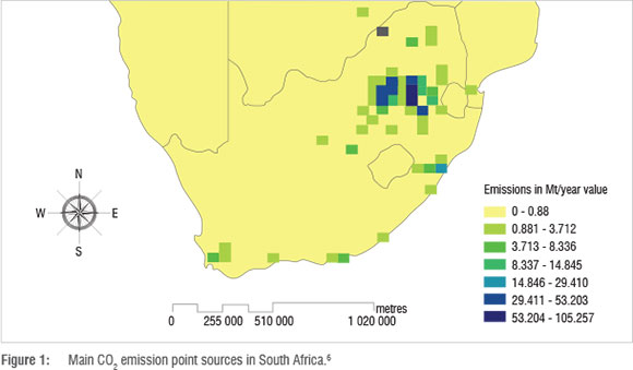
Globally, 78-83% of CO2 emissions can be attributed to electricity generation from fossil fuels.2 In South Africa the situation is no different with almost 93% of the country's electricity needs provided by fossil fuels; 77% of electricity is provided specifically by coal power plants.3,4 Because of the country's abundant coal reserves, the use of relatively inexpensive coal-derived power is unlikely to cease in the next 200 years.3 Coal power plant operations have resulted in South Africa's power sector being the 9th highest CO2 emitting power sector in the world, with an estimated 218 mega tonnes (Mt) of CO2 emitted each year.4,5 Although these emissions are low compared to more developed countries, they are higher than the next nine countries in Africa combined.4 Eskom Ltd., the country's primary electricity utility, is currently the 2nd highest CO2 emitting company in the world, as a result of its utilisation of pulverised coal (PC) combustion plants.
As can be seen in Figure 1, the most significant CO2 emission sources in South Africa are situated in the Gauteng, Mpumalanga and Free State Provinces - not surprisingly, as these provinces form the heart of South Africa's coal mining sector and the regions in which most coal power plants are situated. Figure 1 shows not only the CO2 emissions from coal power plants, but also those from coal-to-liquids industries, gas-to-liquids industries and oil refining processes.
In an effort to reduce CO2 emissions and encourage a move towards a cleaner energy strategy, the South African government is considering proposing a CO2 emissions tax that would be levied on all CO2 emission sources. Recent debates have suggested a tax rate of R75 to R200 per tonne of CO2 emitted; with the most recent and currently applicable cost being R120/tonne CO2 in line with international standards.7 Considering that South Africa's energy industry emits well over 200 Mt of CO2 per annum, the proposed levy will result in significant increases in operating costs for companies in this sector. With Eskom having over the last few years almost doubled its electricity tariff, the proposed CO2 emission tax will further add to the need for Eskom to increase its tariff if it passes on this cost to the consumer. It is therefore imperative that solutions to reduce CO2 emissions be found.
Carbon capture and storage (CCS) is a promising mid- to long-term solution to reduce CO2 emissions. This strategy involves capturing CO2 at power plants and other industries before they are emitted, transporting CO2 to suitable disposal locations, and either storing CO2 underground or utilising CO2 to retrieve high-value products.
In this review, we concentrate on coal power plant operations and their suitability for CCS technology. Techniques that are potentially applicable to CO2 capture in coal power plants are presented, and CO2 transportation, storage and potential uses are discussed with specific relevance to South Africa.
Coal power plant operations
Currently, South Africa possesses 14 PC power plants; 7 of them are in the top 30 highest CO2 emitting power plants in the world.3,5
A simplified schematic of a typical PC power plant is shown in Figure 2. In a PC power plant, coal is transported to a pulveriser via conveyor belts and crushed into a powder with a particle diameter of approximately 50 µm. Hot air then blasts the coal into a boiler where it is burnt. The heat generated is used to heat tubes containing water. These tubes can be kilometres long, but are coiled in order to be compact.8 The water in the heat exchanger tubes is converted into superheated steam at high pressure. The steam is used to drive turbine blades which spin the turbine. The turbine shaft is linked to a generator rotor, which generates electricity using an electromagnet.8 The electricity flows through transmission lines and transformers to reach consumers at the required voltages. The used steam is then cooled and condensed in cooling towers, and recycled to the boilers for reheating.
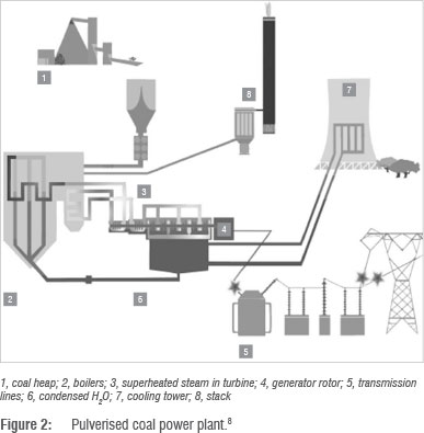
The gases that are released during the coal combustion are filtered using bag filters to remove ash. If the gas mixture contains substantial sulphurous and nitrogenous emissions, particularly SOX and NOX compounds, then desulphurisation and denitrification processes can be installed to remove them, although these processes have currently not been implemented in South African coal power plants. The remaining gases are emitted through a stack as flue gas. Flue gas composition varies according to coal composition and power plant flue gas treatment processes. The typical composition of flue gases is approximately 12-12.8% CO2, 6.2% H2O, 4.4% O2, 50 ppm CO, 420 ppm NOx, 420 ppm SO2 and 76-77% N2. The flue gas is typically emitted at pressures ranging from 100 kPa to 170 kPa and temperatures of 363.15-412.15 K.9-11
PC power plants typically emit CO2 on a magnitude of 514 kg CO2/MWh electricity produced.12
CO2 removal from PC power plants entails retrofitting the power plant with a CO2 capture process to treat the flue gas for selective CO2 removal before it is emitted through the stack. This mode of CO2 capture is known as post-combustion capture, because CO2 capture occurs after coal combustion.
PC combustion is a well-developed and common power plant process that requires a lower investment cost compared to newer technologies. However, CO2 capture and compression is expensive as the flue gas to be treated is available at unfavourably low pressure and high temperature.
Techniques of capturing CO2 from pulverised coal power plants
Currently, there are many gas separation techniques under investigation for post-combustion CO2 capture from PC power plants. This section explains the unique properties of CO2 and presents CO2 capture techniques which exploit these properties for efficient gas separation, despite the unfavourable conditions of post-combustion flue gas at the stack.
Solubility and pH of CO2 in HJO
The solubility of CO2 in water is 0.9 vol CO2/vol H2O or 0.0007 mol CO2/mol H2O at 293.15 K.13,14 CO2 forms weak carbonic acid when dissolved. This dissolution, however, may reduce the pH of water to as low as 5.5.12 This finding is important, as it confirms that CO2 acts as an acid in acid-base reactions, which is vital information in the selection of solvents or sorbents which may be used to absorb or adsorb CO2.
Gas absorption using solvents
The acidic nature of dissolved CO2 in water dictates the types of physical and chemical solvents that would potentially be successful for efficient CO2 absorption. Applicable chemical solvents include amine solvents and solutions, which result in CO2 absorption by zwitterion formation and easy deprotonation by a weak base.11 Promising potential physical solvents include chilled ammonia, Amisol and Rectisol solvents,2 and ionic liquids which consist purely of cations and anions. Huang and Rüther15 discovered that a Lewis acid type interaction occurs between CO2 and anions, with CO2 acting as a Lewis acid and anions acting as a Lewis base.
The selective absorption of CO2 can be achieved by passing the flue gas through an absorber through which solvent flows counter-currently. CO2 is selectively absorbed into the solvent and exits through the bottom, while other flue gas components are passed out through the top of the absorber (Figure 3).
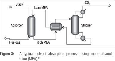
The solvent loaded with CO2 is then heated and sent to a stripping column where desorption occurs. CO2 is released, while the unloaded solvent is recycled to the absorber.
The advantage of this strategy is that the process is well developed as it is already in use for other gas treatment requirements such as desulphurisation and denitrification processes. There are many possible solvents and solvent mixtures that are under investigation for CO2 absorption, including amine and carbonate solvents, as well as ionic liquids.
The disadvantage is the high energy penalty associated with solvent regeneration in the stripping column. CO2 absorption increases with decreasing temperature, requiring flue gas to be cooled for CO2 absorption, as flue gas is available at a relatively high temperature of up to 413 K.16 However, thereafter, the loaded solvent needs to be heated in the stripping column to release CO2 and recycle the solvent. There is ongoing research on finding suitable solvents that are easily regenerated with a much lower energy penalty.
Pilot plants for processes of this type have already been set up in Austria and the Netherlands in 2008.17,18 South Africa's first CO2 capture plant that would likely include solvent absorption is scheduled to be set up by 2020, pending the success of CO2 injection projects19 (Surridge T, 2011, oral and written communication, November 28).
CO2 capture using dry regenerable sorbents
Figure 4 illustrates a sorbent adsorption process. Flue gas is first cooled and then sent to a carbonation reactor, which is a packed or fluidised sorbent bed reactor. CO2 is absorbed or adsorbed into the sorbents. This process may be physical or reactive. The sorbent, now loaded with CO2, is then transferred to a regenerator where it is heated to release the CO2. The sorbent is then recycled to the carbonation reactor.16
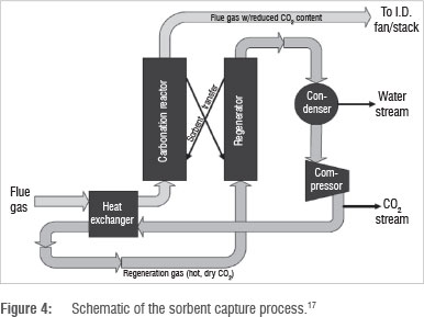
Packed bed reactors are popular for inherently porous activated sorbents while sorbents occurring as pellets, flakes, or fine particulate matter are used in a fluidised bed reactor. The process may operate in continuous or batch mode, depending on the efficiency of solids handling and the CO2 removal capacity of the process.
Common sorbents under investigation for CO2 capture include activated coal, sodium carbonate, potassium carbonate and calcium carbonate.16 CO2 capture is efficient even at low CO2 concentrations in the flue gas. Depending on the sorbent and process design, lower regeneration energy requirements can be achieved than those from absorption using amine solvents.14,17
The low attrition resistance of many sorbents is a fundamental setback to their implementation as a CO2 capture technique.2,18 While single-cycle results seem promising, many sorbents are not robust enough to be used in multi-cycle operation with conventional solids handling techniques. Sorbent pellets may erode or become caked and lose shape. High water content in the flue gas results in further attrition and sorbent caking. Moreover, the expensive nature of solids handling, including conveyor belts and compressed air blast loops which require maintenance, also reduces the feasibility of using sorbents as a CO2 capture technique.
Research, especially on the introduction of additives and sorbent supports and hybrid processes that combine sorbents with solvents, is being conducted to overcome the current challenges experienced with the use of sorbents.20 Details of a pilot plant set-up and usage are provided by Manovic et al.21 who utilised a fixed bed reactor. Fluidised bed pilot projects have also been considered in Canada and Korea.22,23
CO2 molecular size
The CO2 properties presented by the Asia Industrial Gases Association13 show that the CO2 molecule - a carbon atom double bonded to two oxygen atoms - is compact. Also, importantly, the molecule is linear in shape, with a bond length of 116.18 pm, making the molecule approximately 232 pm in length. Figure 5 provides an illustration of the molecule.
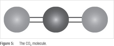
By comparison, the diatomic O2 molecule has a bond length of 120.8 pm, water has a bond length of 102.9 pm and N2 has a bond length of 109.7 pm.24 The size and linear shape of the CO2 molecule in relation to other flue gas components, as well as other properties such as dipole moment and polarisability, facilitates not only the use of sorbents, but also the use of conventional membrane filtration systems, enzymatic membranes and metal organic frameworks to filter out CO2 from smaller molecules of various components of flue gas.
Membrane separation
Figure 6 illustrates a typical membrane contactor. Flue gas enters into a membrane separation unit. CO2 selectively permeates through the membrane while other flue gas components do not. Flue gas passes out as stack gas, while CO2 is recovered and compressed on the other side of the membrane.
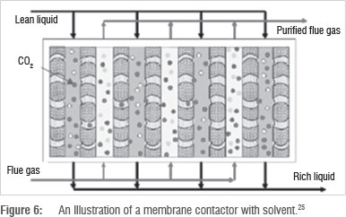
While membranes can be used on their own, increased efficiency is noted when solvents are used as a sweep fluid to accelerate mass transfer and recover CO2 on the other side of the membrane. Some solvents, such as ionic liquids, are combined into the membrane pores to increase CO2 permeability through the membrane.2
Common membrane material includes zeolite, ceramic, polymer and silica. More fragile membranes are supported by alumina to increase their robustness. Depending on the type of filtration unit, the process can operate in batch or continuous mode.
The advantage of membranes is that CO2 can potentially be recovered at high purity. Membrane units are well developed and there is high scope of study regarding membrane types and solvent combinations. If no solvent is used, then solvent regeneration and recycling is not required.
The challenge in implementing membrane separation for CO2 capture is the high pressure that the process demands. The flue gas needs to be compressed before undergoing filtration in order to achieve a high CO2 removal rate, which amounts to a high energy penalty. Moreover, many types of membrane material cannot satisfy optimum CO2 permeability and selectivity constraints and are not robust enough for long-term operation. Satisfying these requirements forms part of ongoing research.
A pilot plant in the Netherlands which accommodates CO2 capture using membranes combined with solvents was constructed in 2008.18
Enzyme-based systems
Instead of using conventional membranes as previously described, enzymes can be used as a liquid membrane suspended between hollow fibre supports for rigidity. As shown in Figure 7, flue gas passes through the liquid membrane. CO2 is hydrated and permeates as carbonic acid (HCO3-) at a faster rate than N2, O2 and other flue gas components. CO2 is recovered under pressure or using a sweep gas on the other side.2
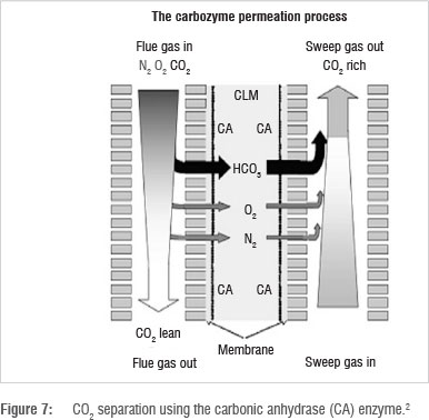
A popular enzyme for CO2 capture is carbonic anhydrase. CO2 recovery with this technique can potentially be as high as 90%.2 About 600 000 molecules of CO2 are hydrated by one molecule of carbonic anhydrase.26 A further advantage is that the heat of absorption of CO2 into carbonic anhydrase is comparatively low.
Disadvantages include limitations at the membrane boundary layers, long-term uncertainty, and sulphur sensitivity of the enzyme,26 prompting ongoing research on new enzymes.
Research in this technique has not gone beyond laboratory studies on CO2 permeability and selectivity.26,27
Metal organic frameworks
Metal organic frameworks (MOFs) are hybrid organic/inorganic structures containing metal ions geometrically coordinated and bridged with organic bridging ligands28 (Figure 8). This arrangement increases the surface area for adsorption, enabling them to be used as sorbents or as nanoporous membranes.
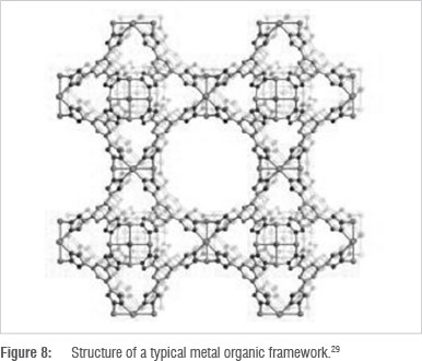
MOFs possess much potential for CO2 capture because there are hundreds of possible MOFs that can be developed using various combinations of metal ions and organic ligands. They can be tailor-made to suit a particular application such as CO2 capture.26 MOFs containing zinc and magnesium ions provide higher CO2 adsorption and are hence being thoroughly investigated.30,31 Another advantage is that regeneration energy required is lower than that for conventional sorbents and solvents.2
The study of metal organic frameworks is still in its infancy, with investigations being made primarily on a laboratory scale.
CO2 phase behaviour
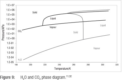
The critical point and triple point of CO2 are 304.25 K and 216.55 K, respectively,13 and the phase behaviour of CO2 shown in Figure 9 also allows for CO2 capture from flue gas by changing conditions of temperature and pressure. Figure 9 shows a wide range of temperature and pressure conditions for the conversion of CO2 from the gas phase into the liquid phase, as well as into the solid phase for storage. Separation processes that make use of the phase behaviour of CO2 include cryogenic separation and hydrate formation.
Cryogenic separation
Cryogenic separation entails the separation of CO2 from flue gas by a phase change, specifically through cooling flue gas until CO2 exists in the liquid or solid phase. Figure 9 indicates that vapour-liquid phase change can occur at temperatures between 217 K and 304 K and pressures from 630 kPa to 7396 kPa. In the case of recovering CO2 in the solid phase at lower temperature, the process is also popularly referred to as CO2 anti-sublimation.
As shown in Figure 10, flue gas is cooled in a heat exchanger and moisture is removed. The resultant dry gas contains CH4, CO2, N2, O2 and trace components such as Hg, SO2 and HCl. The dry flue gas is moderately compressed and sent to a heat exchanger where its temperature is lowered to just above the CO2 solidification point. This temperature varies depending on the operating pressure, which depends on the flue gas conditions from the coal power plant.
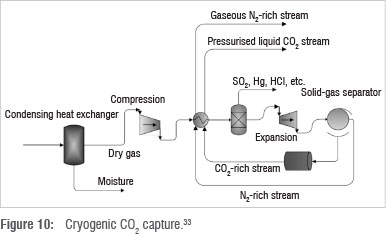
SO2 and other trace compounds from the flue gas are removed using a flash unit which utilises pressure difference to separate components based on volatility. The flue gas then passes through an expander, which causes further cooling and partial precipitation of CO2. CO2 is thus separated from the flue gas, which at this point consists primarily of N2 gas. The CO2 rich stream is further pressurised and recycled, together with the N2 rich stream, to the heat exchanger to cool incoming dry flue gas. The CO2 rich stream undergoes a temperature increase during heat exchange which results in CO2 being produced in the liquid phase at elevated pressure. N2 remains in the gaseous phase and is recovered separately.
As an alternative to applying high pressure to compress the flue gas, simulations have proved CO2 liquefaction to be more energy efficient and cost effective. This technique entails cooling the flue gas instead of compressing it. Energy costs associated with gas compression are reduced, and operating and investment costs for circulation equipment are also reduced.34
The advantage of cryogenic separation is that CO2 can potentially be recovered at 99% purity. Refrigeration processes are already well established. Refrigerants such as n-butane, propane, ethane and methane, or a blend of each, can be used.35
The disadvantage is the high energy penalty associated with cooling flue gas by refrigeration. Flue gas needs to be cooled to 136-194 K,35,36 depending on the concentration of CO2 in the flue gas. Mixed results have been obtained in various studies on the energy penalty and resultant efficiency of cryogenic separation as a CO2 capture method. Some studies suggest that cryogenic separation possesses an 11-27% energy penalty and is 40% more efficient than conventional absorption.35,36 However, other studies estimate that the efficiency of cryogenic separation is 3% lower than absorption and membrane processes.37 Efficiency depends on the CO2 composition in the flue gas and the degree to which pinch technology can be applied.
The CATO (CO2 Afvang, Transport en Opslag) programme in the Netherlands, has developed a pilot plant that also accommodates the study of cryogenic separation.17
Hydrate formation
A separation process which makes use of CO2 and H2O phase behaviour, as well as molecular size and bond lengths, is hydrate formation. This technique entails passing flue gas through a unit containing chilled water at optimum temperature and pressure, causing some components of the flue gas to freeze together with water molecules to form hydrates, which are ice-like crystals in which the gas molecules are trapped inside a cage of water molecules, through hydrogen bonding. Figure 11 shows wide ranges of temperature and pressure that can result in hydrate formation.

The specific formation of CO2-water hydrates industrially can require low temperatures of 268.15-298.15 K, and very high pressures of 3000-50 000 kPa.39 Hydrate formation pressure decreases substantially at temperatures lower than 273 K. Figure 12 shows various hydrate structures. The structures differ depending on the guest molecule. A structure I hydrate is formed with CO2, as a result of the quadrupole nature of the CO, molecule.
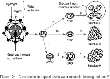
CO2-water hydrates form and exist as ice crystals in a slurry of water, while other flue gas components remain in the vapour phase and are recovered. CO2 is thereafter recovered by heating the ice crystals, which releases the CO2 molecules.
As a result of the size of the CO2 molecules and the resultant ease of hydrate formation, an advantage of this process is its high selectivity; 99% CO2 recovery can be achieved.40 Water is used as an inexpensive recyclable solvent.
The disadvantage is the low temperature and very high pressure required for hydrate formation. Studies are currently being conducted on additives and hydrate formation promoters to reduce the required pressure for hydrate formation, so as to improve the feasibility of the process. Moreover, the handling of slurries results in maintenance problems such as pipeline plugging.
Hydrate formation as a CO2 capture technique is relatively under-developed. There are plans, however, to set up a pilot plant in the USA which caters for hydrate formation.41
CO2 mitigation through the design of new coal power plants
The CO2 capture techniques described above are investigated primarily for their ability to capture CO2 from conventional PC power plants. These techniques are intended to be retrofitted in post-combustion mode to existing PC power plants. However, a further option for future coal power plants is to design the coal combustion process in a manner that would result in favourable flue gas composition and conditions, and hence result in more efficient CO2 capture, from a cost and energy point of view. The main alternative coal combustion processes currently under investigation are integrated gasification combined cycle, oxy-fuel combustion, integrated gasification steam cycle and chemical looping combustion.
Integrated gasification combined cycle
A new alternative power plant process is the integrated gasification combined cycle (IGCC) process. While there are currently no such power plants in South Africa, the process has some advantages over PC power plants and is a more environmentally friendly alternative for new power plant construction.
A simplified schematic of an IGCC power plant is shown in Figure 13. In this process, nearly pure oxygen (O2) is produced using an air separation unit. The O2 is sent to a gasifier together with coal. Combustion in the presence of nearly pure O2 occurs. Coal is partially oxidised to produce a mixture of CO, CO2 and H2, collectively known as syngas.16 The gasifier operates at 3500-7000 kPa and 1255-1644 K. The reactions occurring in the gasifier are43:
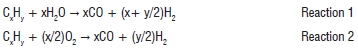
After particulate removal, the syngas is sent to a shift convertor to undergo a water gas shift reaction:
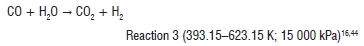
Steam is utilised in the convertor as a reactant. A gas mixture of CO2, H2 and sulphurous and nitrogenous compounds leave the convertor. Unreacted steam is often removed as water. Desulphurisation and denitrification processes are then employed depending on the presence of sulphur- and nitrogen-containing chemicals. The resulting gas mixture contains approximately 50 vol% H2, 40 vol% CO2, 2 vol% CO and other trace elements. The gas occurs at 2700 kPa and 310 K.9
At this point in the process, CO2 may be removed using a feasible CO2 capture technique. CO2 may then be compressed and stored. After CO2 capture, H2 is burned to generate steam at approximately 12 400 kPa45 which is used to drive the turbines and hence generate electricity.
The electricity generated by the turbine is used to power the gasifier, shift convertor, air separation and compression operations. The remaining electrical energy is then available for commercial use.
IGCC processes are estimated to require higher investment costs than PC processes. However, upon integration of CO2 capture into the plant, the total investment cost is lower for IGCC processes than for PC processes which are retrofitted for CO2 capture. IGCC processes also introduce the prospect of pre-combustion capture after shift conversion. CO2 is captured from flue gas at higher pressure, reducing CO2 compression costs. It is these advantages that make IGCC an attractive option if the capacity of coal power in South Africa is expanded.
Oxy-fuel combustion
This technique is a modification of the PC power plant. It involves burning coal in nearly pure oxygen.
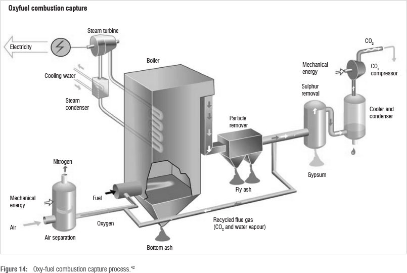
Oxygen is cryogenically separated from air in an air separation unit. Other air components are emitted into the atmosphere while oxygen is used in the boiler for coal combustion. The resulting heat converts water to superheated steam, for use in steam turbines. The resulting flue gas from combustion is treated for ash and sulphur removal, and thereafter contains CO2 and water vapour. Water is separated from CO2 by cooling the flue gas. A schematic of the process is shown in Figure 14.
The main advantage of the process is that the flue gas is available at a high CO2 concentration of approximately 75.7 mol%,46 thereby reducing compression costs and facilitating efficient CO2 removal.2 Moreover, CO2 is easily separated from H2O. The modification of PC to oxy-fuel combustion is also easier than constructing an IGCC process. Oxy-fuel combustion is estimated to inherently result in lower CO2 emissions than IGCC and conventional PC processes.46
The disadvantage is the high flaming temperature at which coal burns in the presence of pure oxygen, which puts much strain on the material of construction.42 To mitigate this, flue gas is recycled to enable temperature control, as shown in Figure 14. Captured and cooled CO2 streams may also assist in lowering the temperature of the boiler. Moreover, air separation units require high amounts of energy to obtain pure oxygen from air. Cryogenic methods are also presently accompanied by high energy penalties.
Integrated gasification steam cycle
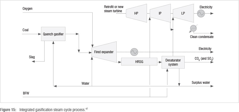
A US consortium consisting of Siemens Ltd., MAN Ltd., CO2 Global, Imperial College London, and Jacobs Consultancy has conducted research into a modified IGCC coal combustion process called integrated gasification steam cycle (IGSC), in order to minimise the energy penalty associated with coal power plants possessing CO2 capture. As seen in Figure 15, waste energy is efficiently utilised through a relatively complex system of recycle streams and turbines of varying pressure.
The process consists of a two-stage combustion system. Coal is gasified in a quench gasifier, which utilises water for temperature control. The resultant syngas contains carbon monoxide, hydrogen gas and oxygen gas, which is passed through a fired expander to generate power. The expander consists of a burner connected to a turbine. Combustion is completed in the expander at temperatures over 1000 K.
The exhaust heat is used to raise high pressure steam in a heat recovery steam generation system, which is then used to power an additional turbine retrofitted to the process. Resultant gases, containing primarily H2O, CO2 and trace SO2, are then cooled in a desaturator to remove H2O and recover CO2 in post-combustion mode. The desaturator utilises recycled cooling water and, if optimised, can drive a low-pressure turbine, generating additional power.47
The advantage is that the process can potentially obtain 100% CO2 recovery and increase power plant output by 60% compared to conventional PC power plants.48 Conventional turbines can be used and CO2 is available at high pressure.
The capital cost - in the form of the air separation units required to provide oxygen to the gasifier - of IGSC processes is their main drawback. A desulphurisation unit may also be required for coal with a high sulphur content.
Research on IGSC is limited solely to the consortium that invented it, barring all possibility of finding data from other independent sources. There is however, abundant information available from the consortium itself.47
Chemical looping combustion
This technique is a further modification of oxy-fuel combustion. Instead of utilising oxygen from an air separation unit for coal combustion, oxygen derived from metal oxides is used.49 As shown in Figure 16, two fluidised bed reactors are used: the air reactor (1) and fuel reactor (3). Particulate metal or metal oxide is oxidised in the air reactor using air, thereby acting as an oxygen carrier. A cyclone (2) is used to separate the carrier from unreacted components of air, which are emitted as flue gas. The particulate oxygen carrier is transferred into the fuel reactor (3).
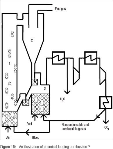
The oxygen carrier is reduced in a combustion reaction with coal and recycled to the air reactor. Flue gas from the fuel reactor contains H2O and CO2, and can be used to drive a turbine before being separated by cryogenic means.
The reactions occur typically at 1173.15-1573.15 K.50 Different metal oxides (such as Fe2O3/CuO and MgAl2O4, nickel, manganese and calcium oxides) can be used as the oxygen carrier.51,52
The advantage of chemical looping combustion is that no air separation unit is required, and flue gas contains primarily CO2 and H2O, with CO2 available at 31wt% in the flue gas, which is higher than conventional PC power plant flue gas.25
The current disadvantage of chemical looping is the high investment cost required for the technology, which deters research and implementation. Another fundamental challenge to implementation is choosing an ideal oxygen carrier. Current studies show the conversion rate under oxidising conditions, using conventional oxygen carriers to be very fast (nearly 100%/min).49 However, the occurrence of side reactions with undesirable products is yet to be minimised.53
Most research on chemical looping that is currently underway is on the finding of a suitable oxygen carrier.44 Despite this, a pilot plant has been developed in Sweden to investigate the industrial operation of chemical looping.49,50
CO2 transportation
After the removal of CO2 from coal power plants and other industrial sources, CO2 needs to be either transported to locations where it is stored or used in various processes. Currently CO2 is transported by road. However, the quantity of CO2 attained from CO2 capture processes may necessitate that CO2 be transported via ship or pipeline. In both cases, the required compression pressure can be 10 000-30 000 kPa,54 depending on the distance and intended disposal or use of CO2. Compressors may need to be installed every 100 km or so for transport over long distances. Hazards such as the acidic nature of CO2 gas have to be taken into account when transporting CO2, particularly if the stream is impure.
CO2 storage
The high heat of formation of CO2 of -393.5 kJ/mol55 provides great difficulty in converting CO2 to high value products, despite current and recent efforts56. While CO2 has many uses in various commercial enterprises, the sheer amount of CO2 that would be captured from industrial processes necessitates alternative disposal methods.
The term 'sequestration' describes the removal of CO2 from the atmosphere and its long-term storage.57 While there are many options to store CO2, the most promising strategy involves injecting CO2 at least 800 m underground, where ambient pressure and temperature are sufficient to result in liquid or supercritical CO2, and into a formation with an impermeable cap rock so that no substantial leakage may occur.54
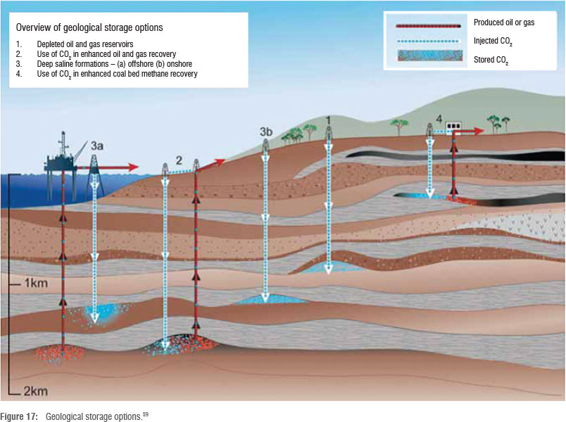
CO2 can be stored in geological formations such as former natural gas, oil or brine fields (saline formations), and un-minable coal beds that contain porous rock (Figure 17). There is also the possibility of storing CO2 in offshore formations of the same nature, but this option is more technically challenging and expensive.
A well-sealed cap rock, containing a layer of shale and clay is essential to prevent upward CO2 migration and leakage.58 This form of storage is known as structural trapping and is the most dominant method of trapping gases underground. Residual trapping occurs to a lesser extent, where CO2 gets trapped in porous rock through displacement and migration. CO2 may also be trapped through dissolution in underground brine solutions present in porous rock, a mechanism known as solubility trapping. Final trapping of CO2 occurs upon formation of carbonic acid and, finally, solid carbonate minerals.59
A good knowledge of the underground reservoir size is needed to account for horizontal migration of CO2 and ensure ultimate trapping by geochemical means, such as carbonate formation from reactions with CO2 and the host rock.54,58
While CO2 capture is relatively underdeveloped for commercial use, CO2 sequestration is already prevalent in oil, gas and coal industries in Canada, Algeria, the USA, Norway, the Netherlands, China, Japan, Poland and Australia.59
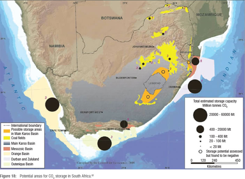
Viljoen58 and Cloete60 present areas in South Africa where CO2 can be stored. These include saline formations (structures of porous rock typically containing mineralised brine solutions in the pores), gas reservoirs and depleted coal mines. The closest area to many of Eskom's operations, and most CO2-emitting industries in general, are parts of the Northern Karoo, which possesses free saline formations, as well as depleted coal mines. Further formations are shown in Figure 18, which includes large offshore storage opportunities as well.
Figure 18 shows that some possible storage sites are relatively close to the CO2-emitting sources shown in Figure 1. CO2 compression and transportation costs via pipelines could be reduced. However, many possible storage sites are far from CO2 emission sources. CO2 storage attempts are currently being planned in South Africa, with a test scheduled for 2016. If CO2 storages tests are successful, CO2 capture implementation tests should be completed by 202019 (Surridge T, 2011, oral and written communication, November 28).
Uses of CO2 storage
In addition to high pressure CO2 storage in porous reservoirs, CO2 may be injected underground to assist in the recovery of high value resources such as oil, natural gas, and methane. These are more feasible solutions that can partially or completely recover the cost of CO2 capture and storage. Below are a few options for CO2 storage. (Refer to Figure 17 for illustrations.)
CO2 enhanced oil recovery
Enhanced oil recovery refers to the strategy of injecting CO2 into nearly depleted oil wells to pressurise the well and force the remaining oil upwards. CO2 also reduces the viscosity of the oil for easier extraction. Once the oil is depleted, the CO2 is sealed off underground. Two boreholes are drilled, one for injecting CO2 and the other to allow the upward migration of oil. Existing boreholes may also be used. Enhanced oil recovery can increase the recovery rate of oil by 8-15%, and can ultimately increase the recovery of oil by up to 50% of the total oil originally recoverable.54
A major enhanced oil recovery project using CO2 has been conducted in Canada.59 Enhanced oil recovery projects using other gases such as N2 and hydrocarbon gas mixtures are also a mature technology.
CO2 enhanced gas recovery
Enhanced gas recovery refers to the extraction of natural gas from nearly depleted gas reservoirs using CO2. Natural gas is a mixture composed of methane and various hydrocarbon gases. After conventional extraction, gas reservoirs still contain 10-20% of their initial capacity.54 Because of the reduced pressure in the reservoir, conventional extraction becomes unfeasible. CO2 injection increases the pressure in the reservoir. Moreover, CO2 is denser than natural gas and sinks to lower regions of the reservoir, forcing natural gas upwards. In this way, the reservoir can be completely emptied of all natural gas. An enhanced gas recovery system is in operation in the Netherlands.59
CO2 enhanced coal bed methane recovery
Enhanced coal bed methane (ECBM) recovery involves the extraction of methane gas from coal seams using CO2. The process of extraction is similar to enhanced gas recovery but is done with coal seams. CO2 is injected into an un-minable or unfeasibly minable coal bed and methane is forced up through a drilled outlet channel. Conventional extraction techniques recover 50% of methane in coal beds. The use of CO2 in ECBM has the potential to increase methane recovery to 90% or even 100%.54
While the strategy seems theoretically attractive in terms of methane recovery, the main concern with ECBM recovery is the potential for CO2 leakage which might occur as a result of the relatively shallow depth of extraction and the permeability of coal seams that are required. Although shallow depth and permeable rock facilitate efficient methane recovery, they also are conducive to permanent, stable CO2 storage.
Moreover, for leakage to be prevented and for predictable channelling of methane and CO2 to occur, the coal bed has to be sufficiently thick, which requires an amount of coal to be left un-mined and the mine must be rendered un-minable. A thorough feasibility analysis is required to ensure that ECBM is worth the cost of un-mined coal. Additionally, coal mines that seem uneconomical to mine presently may be economically minable with technological development in the future. However, CO2 ECBM may render these coal mines permanently un-minable.
ECBM operations are currently underway in Canada, China, Japan and Poland.59 The strategy has some potential in South Africa because of the vast number of coal beds in the country. However, coal beds offer the least amount of storage potential in South Africa and worldwide because of their shallow depth and capacity compared to other types of potential storage reservoirs, and the permanent loss of currently un-minable coal.
Conclusions
Seven main CO2 capture techniques have been identified which show great promise as industrial CO2 emissions mitigation solutions. The technique of CO2 absorption using solvents was identified as currently the best option for industrial implementation as a capture technique. While other techniques are under consideration, the use of solvents is currently the most likely to be implemented in the South African CCS schedule. Other techniques, while potentially more efficient than the use of solvents, still require substantial research to bring them to the stage of industrial implementation. Four power plant modifications or alternative process designs have been identified and are currently at the pilot plant stage of research. No country has as yet issued a full roll-out of these technologies and it remains unclear as to when these designs would be implemented on an industrial scale. The potential areas of CO2 storage have been mapped out, with a test injection due to commence in 2016. Three uses of CO2 storage have been identified to make CO2 storage more economically attractive, but their applicability to South Africa requires more thorough investigation.
Acknowledgements
This work is based upon research supported by the South African Research Chairs Initiative of the Department of Science and Technology and National Research Foundation.
Authors' contributions
D.R. was the project leader and K.O.'s PhD supervisor. C.C. was the co-supervisor of K.O.'s PhD. K.O. undertook the bulk of the literature review and writing of the manuscript. D.R. and C.C. conceptualised and edited the manuscript.
References
1. International Energy Agency (IEA). Key world energy statistics - 2010. Paris: International Energy Agency; 2010. [ Links ]
2. Figueroa JD, Fout T, Plasynski S, Mcllvried H, Srivastava RD. Advances in CO2 capture technology - The US Department of Energy's carbon sequestration program. Int J Greenh Gas Con. 2008;2:9-20. http://dx.doi.org/10.1016/S1750-5836(07)00094-1 [ Links ]
3. Eskom Power Generation. Eskom - coal power [homepage on the Internet]. c2011 [cited 2011 Feb 28]. Available from: http://www.eskom.co.za/live/content.php?Item_ID=279 [ Links ]
4. Carbon Monitoring for Action (CARMA). The 10 largest CO2 emitting power sectors in the world by country [homepage on the Internet]. c2009 [cited 2011 July 04]. Available from: www.carma.org [ Links ]
5. Carbon Monitoring for Action (CARMA). Top 30 CO2-emitting power plants in the world [homepage on the Internet]. c2007 [cited 2011 July 04]. Available from: www.carma.org [ Links ]
6. Surridge T. South African activities related to carbon capture and storage [document on the Internet]. c2005 [cited 2009 Jan 28]. Available from: http://www.cslforum.org/documents/pg_RomeMinutespublic.pdf [ Links ]
7. National Treasury. Carbon Tax Policy Paper - Reducing greenhouse gas emissions and facilitating the transition to a green economy. Discussion paper for public comment [document on the Internet]. c2010 [cited 2013 Aug 07]. Available from: http://www.treasury.gov.za/public%20comments/Discussion%20Paper%20Carbon%20Taxes%2081210.pdf [ Links ]
8. Eskom Ltd. Eskom coal power animation [homepage on the Internet]. c2011 [cited 2011 May 25]. Available from: http://www.eskom.co.za/content/Coal.swf [ Links ]
9. National Energy Technology Laboratory (NETL). Doe/Netl advanced carbon dioxide capture r&d program: Technology update. U.S.A.; National Energy Technology Laboratory; c2010 [cited 25 May 2011]. http://www.netl.doe.gov/technologies/coalpower/ewr/pubs/CO2%20Capture%20Tech%20Update%20Final.pdf [ Links ]
10. Brennecke JF, Gurkan BE. Ionic liquids for CO2 capture and emission reduction. J Phys Chem Lett. 2010;1:3459-3464. http://dx.doi.org/10.1021/jz1014828
11. Asia Industrial Gases Association. Carbon dioxide - Globally Harmonised Document. 7th edn. Singapore: Compressed Gas Association; 2009. Available from: http://www.asiaiga.org/docs/AIGA%20068_10%20Carbon%20Dioxide_reformated%20Jan%2012.pdf [ Links ]
12. US Environmental Protection Agency (EPA). Air emissions [homepage on the Internet]. c2013 [cited 2013 Aug 13]. Available from: http://www.epa.gov/cleanenergy/energy-and-you/affect/air-emissions.html [ Links ]
13. MacColl B. Carbon capture and storage (CCS) - Strategic considerations for Eskom, South African Centre for Carbon Capture and Storage [document on the Internet]. c2011 [cited 2013 Aug 08]. Available from: http://www.sacccs.org.za/wp-content/uploads/2011/11/Day2/CCS%20in%20Utilities%20-%20CCS%20Week.pdf [ Links ]
14. Lentech Water Treatment Solutions. What is carbon dioxide and how is it discovered? [homepage on the Internet]. c2009 [cited 2012 Feb 14]. Available from: http://www.lenntech.com/carbon-dioxide.htm [ Links ]
15. Huang J, Rüther T. Why are ionic liquids attractive for CO2 absorption? An overview. Aust J Chem. 2009;62:298-308. http://dx.doi.org/10.1071/CH08559 [ Links ]
16. Osman K. Carbon dioxide capture methods for industrial sources: A literature review. Energy efficiency and feasibility study [dissertation]. Durban: University of KwaZulu-Natal; 2010. [ Links ]
17. Vierde Nationaal Symposium (VNS). CCS, CATO CO2 catcher, a CO2 capture plant treating real flue gas [homepage on the Internet]. c2008 [cited 2011 Feb 12]. Available from: http://www.co2-cato.nl/modules.php?name=CATO&page=79&symposium=true [ Links ]
18. Knudsen JN, Vilhelmsin PJ, Jensen JN, Biede O. Performance review of castor pilot plant at Esbjerg. Vienna: Dong Energy; 2008.
19. Surridge T. South African activities related to carbon capture and storage -September 2005 [document on the Internet]. c2005 [cited 2011 March 08]. Available from: http://www.cslforum.org/documents/pg_RomeMinutespublic.pdf [ Links ]
20. Green DA, Turk BS, Nelson TO, Box P Gupta RP. Carbon dioxide capture from flue gas using dry regenerable sorbents. Durham, NC: US Department of Energy, National Energy Technology Laboratory; 2004.
21. Manovic V Anthony EJ, Lu DY Sulphation and carbonation properties of hydrated sorbents from a fluidized bed CO2 looping cycle reactor. Fuel. 2008;87:2923-2931. http://dx.doi.org/10.1016/j.fuel.2008.04.023
22. Yi C, Jo S, Seo Y, Lee JB, Ryu CK. Continuous operation of the potassium-based dry sorbent CO2 capture process with two fluidized-bed reactors. Int J Greenh Gas Con. 2007;1:31-36. http://dx.doi.org/10.1016/S1750-5836(07)00014-X
23. Lu DY, Hughes RW, Anthony EJ. Ca-based sorbent looping combustion for CO2 capture in pilot-scale dual fluidized beds. Fuel Proc Tech. 2008;89:1386-1395. http://dx.doi.org/10.1016/j.fuproc.2008.06.011
24. Weast RC, Astle MJ, Beyer WH. CRC handbook of chemistry and physics. 64th ed. Boca Raton, FL: CRC Press; 1983.
25. National Energy Technology Laboratory (NETL). Chemical looping process in a coal to liquids configuration [document on the Internet]. c2007 [cited 2009 Jan 29]. Available from: http://www.netl.doe.gov/energy-analyses/pubs/DOE%20Report%20on%20OSU%20 Looping%20final.pdf [ Links ]
26. Trachtenberg MC, Tu CK, Landers RA, Willson RC, McGregor ML, Laipis PJ, et al. Carbon dioxide transport by proteic and facilitated transport membranes. Int J Earth Space.1999;6:293-302.
27. Ge JJ, Cowan RM, Tu CK, McGregor ML, Trachtenburg MC. Enzyme-based CO2 capture for ALS [document on the Internet]. c2011 [cited 2011 Aug 04]. Available from: http://www.carbozyme.us/publications/P5.pdf [ Links ]
28. Plasynski S, Lang DA, Richard W. Carbon dioxide separation with novel microporous metal organic frameworks [document on the Internet]. c2011 [cited 2011 Aug 04]. Available from: http://www.netl.doe.gov/publications/factsheets/project/Proj315.pdf [ Links ]
29. Long J. New metal organic frameworks in action for capturing carbon dioxide [document on the Internet]. c2010 [cited 2011 Aug 04]. Available from: http://www.greenoptimistic.com/2010/06/02/metal-organic-frameworks-carbon-dioxide-capture/ [ Links ]
30. Yazaydin AO, Snurr Q, Park TH, Koh K, Liu J, LeVan MD, et al. Screening of metal-organic frameworks for carbon dioxide capture from flue gas using a combined experimental and modelling approach. J Am Chem Soc. 2009;131:18198-18199. http://dx.doi.org/10.1021/ja9057234
31. Simmons JM, Wu H, Zhou W, Yildirim T Carbon capture in metal-organic frameworks - A comparative study. Energy Env Sci. 2011;4:2177-2185. http://dx.doi.org/10.1039/c0ee00700e
32. Chemicalogic. Steamtab [homepage on the Internet]. c1999 [cited 2012 Feb 14]. Available from: http://www.chemicalogic.com/download/phase_diagram.html [ Links ]
33. Burt S, Baxter A, Baxter L. Cryogenic CO2 capture to control climate change emissions [document on the Internet]. c2011 [cited 2011 June 21]. Available from: http://www.sustainablees.com/documents/Clearwater.pdf [ Links ]
34. Xu G, Li L, Yang YTian L, Liu T, Zhang K. A novel CO2 cryogenic liquefaction and separation system. Energy. 2012;42:522-529. http://dx.doi.org/10.1016/j.energy.2012.02.048
35. Clodic D, Hitti R, Younes M, Bill A, Casier F. CO2 capture by anti-sublimation: Thermo-economic process evaluation. 4th Annual Conference on Carbon Capture and Sequestration; 2005 May 2-5; National Energy Technology Laboratory, Alexandria, VA, USA. p. 1-5. [ Links ]
36. Baltus RE, Culbertson BH, Dai S, Liu H, DePaolo DW. Low-pressure solubility of carbon dioxide in room-temperature ionic liquids measured with a quartz crystal microbalance. J Phys Chem B. 2004;108:721-727. http://dx.doi.org/10.1021/jp036051a
37. Gottlicher G, Pruschek R. Comparison of CO2 removal systems for fossil-fuelled power plant processes. Eng Conv Manage. 1997;38:173-178. http://dx.doi.org/10.1016/S0196-8904(96)00265-8
38. Sloan ED, Koh C. Clatrate hydrates of natural gases. 3rd ed. New York: CRC Press; 2012.
39. Jadhawar P Mohammadi AH, Yang JT, Tohidi B. Subsurface carbon dioxide storage through clathrate hydrate formation. Edinburgh: Institute of Petroleum Engineering, Heriot-Watt University; 2006.
40. Chatti I, Delahaye A, Fournaison L, Petitet JP. Benefits and drawbacks of clathrate hydrates: A review of the areas of interest. Eng Con Manage. 2005;46:1333-1343.
41. Tam SS, Stanton ME, Ghose S, Deppe G, Spencer DF, Currier RP et al. A high pressure carbon dioxide separation process for IGCC plants [document on the Internet]. c2011 [cited 2011 July 09]. Available from: http://www.netl.doe.gov/publications/proceedings/01/carbon_seq/1b4.pdf. [ Links ]
42. Arshad MW. CO2 capture using ionic liquids [Master's dissertation]. Lyngby: Technical University of Denmark; 2009. Available from: http://docs.google.com/viewer?a=v&q=cache:uF9eKE4Xeg0J:orbit.dtu.dk/getResource%3Fre cordId%3D240068%26objectId%3D1%26versionId%3D1+Non+fluorinated+Ionic+Liquids+%2B+CO2+capture&hl=en&pid=bl&srcid=ADGEESg9aXin_GbLKmM6LyI0ZwZISYo9jdm6WoHXOZShMxVHKwcdqJ9348xr_ET4Di bAHbAcF09sbUcIgJSDpEtHdGpt8LdGo4lv02MgmONX0xD9Dj8r9vXvxaAYZI1cbkOF3ovX0axf&sig=AHIEtbRXq7UJoi74_T-CVBR3d5zuDcG5EQ [ Links ]
43. Steeneveldt R, Berger B, Torp TA. CO2 capture and storage: Closing the knowing-doing gap. Chem Eng Res Des. 2006;84:739-763. http://dx.doi.org/10.1205/cherd05049
44. Kanniche M, Bouallou C. CO2 capture study in advanced integrated gasification combined cycle. App Therm Eng. 2007;27:2693-2702.
45. Department of Energy. Cost and performance baseline for fossil energy plants: Bituminous coal and natural gas to electricity. US National Energy Technology Laboratory report, 2007. [ Links ]
46. Davison J. Performance and costs of power plants with capture and storage of CO2. Energy. 2007;32:1163-1176. http://dx.doi.org/10.1016/j.energy.2006.07.039
47. Karmarkar M, Griffiths J, Russell A, Allen R, Austell M, Trusler M. Industrial and utility scale IGSC coal power stations [document on the Internet]. c2011 [cited 2011 Aug 03]. Available from: http://webarchive.nationalarchives.gov. uk/+/http://www.berr.gov.uk/files/file52638.pdf [ Links ]
48. Kent R. New power cycles with carbon capture and sequestration [document on the Internet]. c2011 [cited 2011 Aug 03]. Available from: http://www.wcsawma.org/sitebuildercontent/sitebuilderfiles/34.pdf [ Links ]
49. Mattisson T, Lyngfelt A. Applications of chemical-looping combustion with capture of CO2 [document on the Internet]. c2011 [cited 2011 Aug 08]. Available from: http://www.entek.chalmers.se/~anly/symp/01mattisson.pdf [ Links ]
50. Mattisson T. Chemical looping combustion using gaseous and solid fuels. International Energy Agency (IEA) Greenhouse Gas R&D Programme [document on the Internet]. c2007 [cited 2011 Aug 08]. Available from: http://www.co2captureandstorage.info/docs/oxyfuel/MTG2Presentations/Session%2006/22%20-%20T.%20Mattisson%20(Chalmers%20University).pdf [ Links ]
51. Wang S, Wang G, Jiang F, Luo M, Li H. Chemical looping combustion of coke oven gas by using Fe2O3/CuO with MgAl2O4 as oxygen carrier. Energy Env Sci. 2010;3:1353-1360. http://dx.doi.org/10.1039/b926193a
52. Fang H, Haibin L, Zengli Z. Advancements in development of chemical-looping combustion: A review. Int J Chem Eng. 2009;2009:1-16. http://dx.doi.org/10.1155/2009/710515
53. Wall T, Liu Y Chemical looping combustion and CO2 capture: Status and developments [document on the Internet]. c2011 [cited 2011 Aug 08]. http://www.ccsd.biz/publications/files/TN/TN%2032%20Chem%20looping%20updated_web.pdf [ Links ]
54. International Energy Agency (IEA). Prospects for CO2 capture and storage [document on the Internet]. c2004 [cited 2009 Mar 05]. Available from: http://www.iea.org/textbase/nppdf/free/2004/prospects.pdf [ Links ]
55. Perry RH, Green DW. Perry's chemical engineers' handbook. 7th ed. New York: McGraw Hill; 1997.
56. LAgence de l'Environnement et de la Maîtrise de l'Energie (ADEME). Panorama des voies de valorisation du CO2 [Overview of the paths of valorisation of CO2]. Angers: l'Agence de l'Environnement et de la Maîtrise de l'Energie (ADEME); 2010.
57. Teng F, Tondeur D. Efficiency of carbon storage with leakage: Physical and economical approaches. Energy. 2006;32:540-548. http://dx.doi.org/10.1016/j.energy.2006.07.027
58. Viljoen JHA, Stapelberg FDJ, Cloete M. Technical report on the geological storage of carbon dioxide in South Africa [document on the Internet]. c2011 [cited 2011 June 30]. Available from: http://www.ccsconference.co.za/images/presentations/thinus_cloete.pdf. [ Links ]
59. Intergovernmental Panel on Climate Change (IPCC). Carbon dioxide capture and storage: Summary for policy makers and technical summary [document on the Internet]. c2005 [cited 2011 Jan 26]. Available from: http://www.climnet.org/EUenergy/IPCC_CCS_0905.pdf. [ Links ]
60. Cloete M. Atlas on geological storage of carbon dioxide in South Africa [document on the Internet]. c2010 [cited 2011 June 30]. Available from: http://www.sacccs.org.za/wp-content/uploads/2010/11/Atlas.pdf. [ Links ]
61. CO2 Capture Project. CO2 trapping mechanisms [homepage on the Internet]. c2008 [cited 2013 Aug 12]. Available from: http://www.co2captureproject.org/co2_trapping.html [ Links ]
 Correspondence:
Deresh Ramjugernath
School of Chemical Engineering, University of KwaZulu-Natal
Howard College Campus
King George V Avenue
Durban 4041, South Africa
Ramjuger@ukzn.ac.za
Received: 17 June 2013
Revised: 01 Oct. 2013
Accepted: 22 Nov. 2013

