


Serviços Personalizados
Artigo
 Inglês (pdf)
 Artigo em XML
 Referências do artigo
Indicadores

Links relacionados
-
 Citado por Google
 -
 Similares em Google
Compartilhar

 Permalink
South African Journal of Science
versão On-line ISSN 1996-7489
versão impressa ISSN 0038-2353
S. Afr. j. sci. vol.110 no.1-2 Pretoria Jan. 2014
RESEARCH ARTICLE
A centrifugal microfluidic platform for point-of-care diagnostic applications
Suzanne HugoI; Kevin LandI; Marc MadouII; Horacio KidoII
IMaterials Science and Manufacturing, Council for Scientific and Industrial Research, Pretoria, South Africa
IIDepartment of Mechanical and Aerospace Engineering, University of California, Irvine, CA 92697, USA
ABSTRACT
Microfluidic systems enable precise control over tiny volumes of fluid in a compact and low-cost form, thus providing the ideal platform on which to develop point-of-care diagnostic solutions. Centrifugal microfluidic systems, also referred to as lab-on-a-disc or lab-on-a-CD systems, provide a particularly attractive solution for the implementation of microfluidic point-of-care diagnostic solutions as a result of their simple and compact instrumentation, as well as their functional diversity. Here we detail the implementation of a centrifugal microfluidic platform - the first of its kind in South Africa - as a foundation for the development of point-of-care diagnostic applications for which both the need and impact is great. The centrifugal microfluidic platform consists of three main components: a microfluidic disc device similar in size and shape to a CD, a system for controlling fluid flow on the device, and a system for recording the results obtained. These components have been successfully implemented and tested. Preliminary test results show that microfluidic functions such as pumping and valving of fluids can be successfully achieved, as well as the generation of monodisperse microfluidic droplets, providing a complete centrifugal microfluidic platform and the building blocks on which to develop a variety of applications, including point-of-care diagnostics. The lab-on-a-disc platform has the potential to provide new diagnostic solutions at the point-of-need in health- and industry-related areas. This paves the way for providing resource limited areas with services such as improved, decentralised health-care access or water-quality monitoring, and reduced diagnosis times at a low cost.
Keywords: microfluidics; centrifugal microfluidics; lab-on-a-disc; point-of-care; diagnostics
Introduction
The technology of microfluidics entails the precise and automated control of very small volumes of fluids, usually on a nanolitre scale. A number of comprehensive reviews detail the advances that have been made in microfluidic technologies over the last 30 years.1,2 Microfluidic systems are often referred to as lab-on-a-chip systems or micro-Total-Analysis-Systems (microTAS), and are well suited to the development of point-of-care diagnostics3-5 as these systems utilise a small sample to provide a compact and low-cost solution.
Centrifugal microfluidic systems, also referred to as lab-on-a-disc or lab-on-a-CD solutions, provide a particularly attractive solution for the implementation of microfluidic point-of-care diagnostic systems, specifically for biomedical applications.6 Centrifugal microfluidic technology makes use of a disc, similar in size and shape to a CD or DVD, to house microfluidic channels and features. A motor is used to rotate the microfluidic disc, transporting fluid radially outwards through the microfluidic device, and manipulating fluid by means of various microfluidic functions and features on the disc. Functions such as valving, mixing, pumping and separation of fluids can be readily achieved in centrifugal microfluidic systems by exploiting the forces responsible for fluidic control. Fluidic control in lab-on-a-disc microfluidics depends on centrifugal forces, Coriolis forces and capillary action.
Centrifugal force is the driving force for fluid transport in lab-on-a-disc systems and causes fluid to flow radially outward from the centre of the disc to the outer circumference. The centrifugal force can be mathematically described by

where p is the mass density of the fluid, ω is the rotational frequency and r is the radial position along the disc. The centrifugal force is particularly useful for facilitating fluid flow through a system, as well as for sedimentation or separation of a sample (centrifugation) and for compression of fluid.
The Coriolis force is the force moving perpendicular to the centrifugal force and is described by

where p is the mass density of the fluid, ω is the rotational frequency and v is the vector of flow velocity. The Coriolis force can be used for mixing of samples in a lab-on-a-disc microfluidic device, as well as for flow switching, or moving of a sample into a specific channel path (e.g. moving a sample into the left channel where a fork occurs in the main channel).
Capillary action is often used to balance the centrifugal force of a lab-on-a-disc system in order to create valves. Once the burst frequency - the rotational speed at which the centrifugal and capillary forces balance each other - is reached and the centrifugal force exceeds the capillary force, the valve will burst, releasing the fluid. The capillary force is described by

where σ is the surface tension, θ is the contact angle and r is the radius of the capillary. Capillary action is useful for valving of fluids as well as for volume metering, which is important in many biological assays. The reader is referred to a number of excellent reviews6-8 for more detailed explanations of the theory surrounding these forces and the application thereof to microfluidic functions.
Centrifugal microfluidic systems are well suited to integrated point-of-care diagnostic systems - and have a number of advantages over existing microfluidic and other point-of-care diagnostic methods.7,9 The lab-on-a-disc platform eliminates the need for active elements such as pumps, actuators and active valves. These components present a complex and costly challenge in many microfluidic systems.7,9 In centrifugal microfluidic systems, pumps, valves and other fluidic functions are achieved primarily using centrifugal forces, with only a small motor required to power the system. A high degree of parallelisation is also offered by centrifugal microfluidics, as numerous devices can be implemented on one disc as a result of radial symmetry. Examples of centrifugal microfluidic applications for biomedical diagnostics have been presented and include blood plasma separation10 and a variety of biological assay implementations.11-13
The simple, low-cost and multiplex nature of the lab-on-a-disc platform is further strengthened by the low-cost and rapid fabrication techniques that can be utilised to realise the disc devices. Simple layered designs manufactured from plastics and adhesives can be used to fabricate microfluidic discs quickly and effectively. Centrifugal microfluidic systems enable a variety of components from sample preparation through to detection to be implemented efficiently into an integrated microfluidic solution for point-of-care diagnostic applications.14
In addition to the low-cost implementation of the lab-on-a-disc platform, centrifugal microfluidics have the added benefit of an accelerated route to market, as they can be viewed as microfluidic applications that are compatible with various existing and commercially available technologies.15 Existing equipment such as CD players, DVD drives and laboratory centrifuges can be used to drive the microfluidic discs and analyse the results, eliminating the need for extensive development on the reader/actuator component of the point-of-care device. The compatibility of lab-on-a-disc devices with commercially available readers is of particular benefit for developing countries, as this compatibility enables a readily accessible solution where it is needed most.
The work presented here details the implementation of a centrifugal microfluidic platform - the first of its kind to be established in South Africa - with the aim of enabling the development of point-of-care diagnostic applications. It is believed that this platform will have the potential to assist in addressing health-related issues in developing countries.
Initial applications of the centrifugal microfluidic platform are designed to showcase the platform and test the various components which are required for this implementation. This includes sample preparation steps for performing blood analyses, as well as investigation of diverse microfluidic applications such as droplet generation.
The final goal of this platform development is to enable research and development activities towards the realisation of microfluidic-based point-of-care diagnostic solutions for South Africa.
Centrifugal microfluidic platform
The lab-on-a-disc platform consists of three main components: a microfluidic disc device, a system for controlling fluid flow on the device and a system to record the results obtained. These components have been successfully implemented into an integrated system including programmable spin cycles and both macro imaging and microscopy. The integrated components provide a complete centrifugal microfluidic platform on which to develop new and novel applications in fields such as point-of-care health diagnostics, environmental diagnostics and chemical and biological production.
Microfluidic disc design, manufacture and assembly
Centrifugal microfluidic disc devices can be designed using a computer aided design (CAD) program such as Solidworks or DesignCAD and manufactured in-house. The microfluidic discs were made from polycarbonate sheeting (Naxel, supplied by Maizey Plastics, Pretoria, South Africa) and pressure-sensitive adhesive (Flexmount DFM 200 clear V-95 150 Poly H-9 V-95 400 H-9, Flexcon, supplied by Synchron, Johannesburg, South Africa), assembled in layers. The various features of the microfluidic disc, including channels and chambers, were machined using different materials and methods. The polycarbonate layers were machined using a milling machine (ProtoMat S63, LPKF Laser and Electronics, supplied by Cadshop (Pty) Ltd, Johannesburg, South Africa), while the pressure-sensitive adhesive layers were cut out using a vinyl cutter plotter (Roland GX-41 CAMM 24" x 12", supplied by Telpro Management, Johannesburg, South Africa). Individual pieces were then assembled and pressed together using a cold roll laminator (ML25, Drytac, supplied by MyBinding, Hillsboro, OR, USA) to produce the finished microfluidic disc device.
Fluid control and analysis of disc
After assembly of the device, the disc was tested using a system that consists of a motor to rotate the disc, as well as an image capturing unit that allows for a picture of an area of interest to be captured for each revolution of the disc. Different rotational speeds and timing cycles were used to implement various fluidic functions (including valving, mixing, sedimentation, separation and compression) by exploiting centrifugal forces.
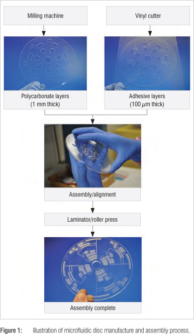
Figure 2 shows the disc testing set-up that was assembled to enable fluid control on the microfluidic disc and imaging of the device as it rotates to enable results of the fluidic functions on the disc to be recorded. A schematic representation of the test set-up is given in Figure 2a, with a photograph of the laboratory set-up given in Figure 2b.
A motor and controller (Smartmotor SM3450D, supplied by Animatics, Memmingen, Germany) were used to control the rotation of the microfluidic disc. An imaging set-up, consisting of an optical sensor (D10DPFP Banner, supplied by RET Automation Controls (Pty) Ltd, Johannesburg, South Africa), fibre optic cable (0.5 mm Fiber Plastic, Banner, supplied by RET Automation Controls), a CMOS camera (DFK 22BUC03, supplied by The Imaging Source, Bremen, Germany) and lens (C1614-M(KP), The Imaging Source), as well as a strobe light (DT-311A Stroboscope, Shimpo, supplied by Resonance Instruments (Pty) Ltd, Johannesburg, South Africa), was constructed. The optical sensor and fibre optic cable served as a trigger to the camera and the strobe light to allow for a clear still image to be captured each time the disc completed a revolution. A small piece of reflective tape was attached to the microfluidic disc to be tested to allow the transmitted light from the optical sensor to be reflected into the receiver of the optical sensor, in turn triggering the camera to capture an image, and triggering the strobe light to illuminate the region of interest on the microfluidic disc, ensuring that a clear still image was captured.
The user controls the rotation of the microfluidic disc or spin cycle via a user interface on a PC. The user can program the speed, acceleration, deceleration and timing cycles of the disc to automate fluidic functions on the microfluidic disc.
Platform and scale-up costs
The lab-on-a-disc platform allows for rapid, low-cost prototyping and testing of microfluidic disc devices, as the equipment and materials required are low cost and/or available in-house. Equipment such as the milling machine and vinyl cutter are common items in many mechanical laboratories. Excluding the equipment which was already available in-house, the costs to produce a complete centrifugal microfluidic system amounted to R25 000. The cost of materials for the disc devices amounted to R500/m2 and R10 per prototype disc device.
A comparison of system integration criteria for various microfluidic technologies16 shows that centrifugal microfluidic systems rank highly as viable, low-cost solutions for integrated lab-on-a-disc systems.16 Sin et al.'s figure 9 illustrates that centrifugal microfluidic systems are second only to paper or capillary-based microfluidic systems in terms of cost, and perform well in other important areas such as throughput and diversity, which would be favourable for point-of-care devices.


Although the lab-on-a-disc system is in the early stages of development, scale-up of the system is an ongoing consideration. Low-cost fabrication of plastic disc devices in high volumes is achievable through readily available manufacturing technologies, while the device for controlling the disc and performing tests is envisioned as a compact system housing a simple motor and measurement mechanism. Scale-up will continue to be considered and developed based on the desired end application of the system.
To ensure the successful development of the lab-on-a-disc system into a viable medical diagnostic product, medical device regulatory requirements will be an important consideration. Role players in the regulatory environment are currently being engaged to determine the requirements for the South African market.
Results
Initial applications of the complete centrifugal microfluidic platform were implemented to illustrate the process carried out from design to analysis of a lab-on-a-disc system. The first example demonstrates basic fluidic functions on the disc such as introduction, valving and combining of fluids, and illustrates potential diagnostic applications for manipulation of biological samples such as blood. The second example demonstrates microfluidic droplet generation using the centrifugal microfluidic platform.
Basic fluidic functions
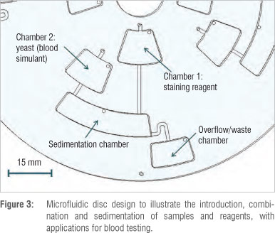
To demonstrate basic fluidic functions, a simple microfluidic disc design was formulated to allow for a sample and a sample reagent to be introduced separately, added together at different times, and combined, with an overflow chamber for excess solution. For the purposes of illustration, a yeast solution was used to simulate blood, while the reagent was a staining solution commonly used to stain blood cells for visualisation and performing manual blood cell counting. The use of a yeast solution as a proxy also allowed the sedimentation or separation of particles in fluids to be illustrated by the centrifugal microfluidic system.
Figure 3 shows the microfluidic features of the disc design used to achieve the desired fluidic functions. Four identical microfluidic systems were designed and manufactured on one disc. The microfluidic channels are 1 mm wide and 100 µm deep, while the chambers have a depth of 1.2 mm and vary in width and length. The vent holes have a diameter of 1 mm.
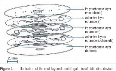
Figure 4 shows the complete composition of the microfluidic disc manufactured from three layers (first, third and fifth layers) of 1-mm thick polycarbonate and two layers (second and fourth layers) of 100-um thick pressure-sensitive adhesive. Sample inlet holes and air vent holes are situated on the top polycarbonate layer, the chambers are situated in the middle polycarbonate layer and both the pressure-sensitive adhesive layers and the channels are situated in the bottom pressure-sensitive adhesive layer.
The blood simulant solution was made from 10 mg dry baker's yeast in 100 mL deionised water to yield a similar concentration of cells to that of white blood cells found in a human blood sample. The staining reagent was a 2% acetic acid solution with 1 mg crystal violet in 100 mL deionised water - a standard white blood cell reagent commonly used to lyse red blood cells and stain the nuclei of white blood cells for manual white blood cell counting.
Approximately 70 µL of both the staining solution and the yeast solution were pipetted into chambers 1 and 2, respectively, via the inlet holes on top of the chamber openings (Figure 3). The microfluidic disc was then placed on the motor spindle of the centrifugal microfluidic platform setup for testing of the fluid functions.
The motor was controlled through the SmartMotor Interface software issued with the motor hardware. The motor was set to operate at a constant velocity to enable continuous rotation of the disc on the motor spindle. For each change in the speed of the rotating disc, an acceleration of 350 rpm2 was used. Figure 5a shows a sequence of images of the microfluidic disc rotating at various speeds to achieve different fluidic functions. Figure 5b shows the corresponding sketches of each of the images in Figure 5a to illustrate the fluidic operations for each step. In Figure 5a, the yeast solution is visible as a bright white colour, while the staining reagent is a deep blue/purple.
The motor was initially set to rotate at a speed of 100 rpm. Referring to Figure 5, it can be seen that, at this speed, no fluid movement occurs and both the yeast solution and the staining reagent stay in the inlet chambers into which they were introduced. At 200 rpm, the fluid in both the inlet chambers starts to compress and is pushed to the bottom of the chambers. At a slight increase in rotational speed up to 280 rpm, the staining solution from chamber 1 is released via a channel into the sedimentation chamber. The fluid is released as a result of the centrifugal force exceeding the capillary force - commonly referred to as the burst frequency. Increasing the speed further to 320 rpm causes the yeast solution from chamber 2 to prime the connecting channel to the sedimentation chamber. At a slightly higher speed of 350 rpm, the yeast solution from chamber 2 is released fully into the sedimentation chamber, combining with the staining reagent. At 500 rpm, the inlet chambers have been completely emptied and the fluid is combined in the sedimentation chamber.
Figure 6 illustrates the sedimentation of fluids in the microfluidic disc, again by making use of the yeast solution as it contains cells or particulate matter. Fluids were introduced into the same disc design in the same manner as in Figure 5. In this example, the yeast solution used was a higher concentration (approximately 10 g dry baker's yeast in 100 mL deionised water) for ease of visualisation of the sedimentation process. This concentration is also similar to the concentration of both red and white blood cells found in a sample of human blood. The staining reagent used was again a 2% acetic acid solution with 1 mg crystal violet in 100 mL deionised water.
A sequence of images from the rotating disc device are shown in Figure 6a, with corresponding sketches of the fluidic operations for each of these images illustrated in Figure 6b. At 350 rpm, both the yeast solution and the staining reagent are in the process of being released into the sedimentation chamber, as in Figure 5. However, Figure 6 clearly illustrates, as a result of the higher concentration of yeast, how the fluids combine in the sedimentation chamber. Although the yeast solution is released after the staining reagent, the yeast solution starts to move to the bottom of the sedimentation chamber as a result of the centrifugal forces. At an increased speed of 500 rpm, sedimentation of the yeast solution from the staining reagent is clearly visible, and at 700 rpm the inlet chambers have been completely emptied into the sedimentation chamber and compressed sedimentation of the yeast solution is visible. Again, the acceleration used for the adjustment of each rotational speed was 350 rpm2.
Microfluidic droplet generation
After successfully demonstrating the implementation of basic fluidic functions from design through to analysis on the centrifugal microfluidic platform, microfluidic droplet generation using the centrifugal microfluidic platform was also investigated. Droplet generation in microfluidic devices is an extensive area of research with a vast number of applications, and has been summarised in a number of useful reviews.17,18
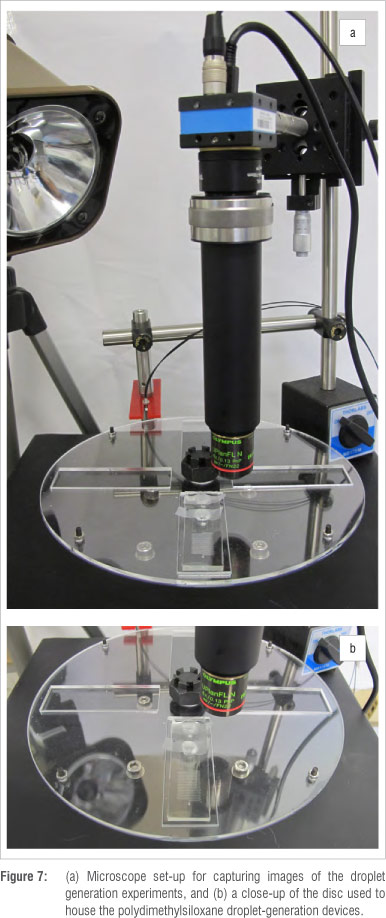
A large poly(methyl methacrylate) (PMMA) disc was designed and manufactured to house existing droplet generation devices (Figure 7). The droplet generation devices, which produce monodisperse droplets, are currently being used for the production of self-immobilised enzymes, which would find application in chemical, food, textile and other industries.
The existing droplet generation devices are made out of poly-dimethylsiloxane (PDMS) using soft lithography techniques to manufacture micro-channel features. The PDMS layer that houses the micro-channels is bonded to a glass slide to create a complete microfluidic device for testing. Typically these devices are tested using syringe pumps to introduce fluid to the devices. Desired flow rates can be programmed into the syringe pumps. For testing the PDMS droplet generation devices using the centrifugal microfluidic platform, the microfluidic devices were manufactured with relatively large reservoirs (8-mm diameters), allowing for a larger volume of fluid to be stored on the microfluidic disc and used during a droplet generation experiment.
A microscope set-up was implemented using various attachments connected to the CMOS camera (DFK 22BUC03, The Imaging Source) of the centrifugal microfluidic platform. The microscope set-up consisted of (in the order in which they were connected to the CMOS camera): a SM1 to C mount adaptor (SM1A9, supplied byThorlabs, Newton, NJ, USA), a tube lens (AC254-030-A-ML, Thorlabs), two lens tubes (SM1ZM, SM1L40, Thorlabs), an RMS adaptor (SM1A3, Thorlabs), and a microscope objective (UPLFLN 4X, Olympus, supplied by Wirsam Scientific and Precision Equipment (Pty) Ltd, Johannesburg, South Africa). This set-up enabled images of the droplet generation on the rotating microfluidic disc to be captured (Figure 7). The large PMMA disc allowed for PDMS devices to be mounted on the centrifugal microfluidic platform. The reservoirs on the PDMS devices were filled with mineral oil as the continuous phase and blue dye in deionised water as the droplet phase.
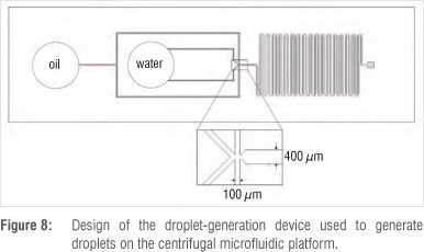
Figure 8 shows the design of the droplet generation device manufactured from PDMS. The channel widths of the PDMS device are 100 µm at the inlets and 400 µm at the outlet. The depth of the device is 70 µm.
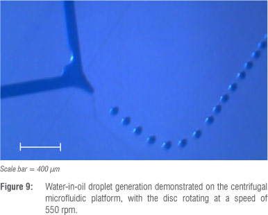
The PDMS devices were mounted to the PMMA disc with the reservoirs filled with mineral oil (with surfactant 3% by weight of Span 80) and deionised water with blue dye and observed at varying rotational speeds. At approximately 550 rpm, monodisperse water droplets in an oil phase were produced with high stability (Figure 9).
Discussion
The centrifugal microfluidic platform was successfully assembled. The design, manufacture and assembly processes were then successfully implemented and tested. The microfluidic disc control and analysis set-up was also successfully established, with hardware and software interfaces designed and implemented. A complete design-to-analysis example was developed, which illustrated the success of the integration of the various components of the centrifugal microfluidic platform. The ability of the centrifugal microfluidic platform to implement diverse microfluidic functions was illustrated by generating monodisperse water droplets in oil.
The results of the microfluidic disc example illustrate microfluidic functions as would be required for diagnostic applications, with particular relevance to blood tests. The microfluidic disc example illustrates that a biological sample can be added to an inlet chamber, with an appropriate sample preparation reagent - such as a lysing and/ or staining reagent - contained in a separate chamber on the disc. The sample and reagent can then be added together in a controlled manner and contained for a required period of time.
Sedimentation of particles in fluids can also readily be achieved using the centrifugal microfluidic platform and could be useful in various diagnostic applications where cells need to be separated out of a sample. Sedimentation using the centrifugal microfluidic platform could be of use in blood tests in which plasma and blood cells are required to be separated, for example for the packed cell volume or haematocrit tests which form part of a full blood count, as well as for various other assays which make use of plasma as a sample.
The results of the droplet generation experiments illustrate that monodisperse droplets can be generated on the centrifugal microfluidic platform with high stability. This example also illustrates the ease with which existing PDMS microfluidic devices with fine microfluidic features can be integrated with the centrifugal microfluidic platform. A low-cost and simple microscope system was established for the centrifugal microfluidic platform, creating a basis on which to test and observe a variety of microfluidic devices at a high level of detail.
Microfluidic functions can be implemented on the centrifugal microfluidic platform with relative ease. In addition, the microfluidic disc manufacture process is simple, rapid and low cost, making it an ideal disposable component for point-of-care applications as well as allowing for rapid development of devices as a result of efficient prototyping. In addition, the radial symmetry of the microfluidic discs lends itself to multiplexed applications, where an array of tests can be carried out simultaneously on one disc. Similarly, a number of identical tests for different samples can be carried out on the same disc at the same time, increasing the throughput for the desired diagnostic application.
Fluid actuation of the lab-on-a-disc system is also simple and robust, using only a motor rotating at various speeds to achieve a vast array of functionality. The centrifugal microfluidic platform thus also has the potential to be developed into a compact, robust and simple system, ideally suited to point-of-care applications.
Conclusion
The lab-on-a-disc centrifugal microfluidic platform is a first of its kind in South Africa and has the potential to provide new diagnostic solutions at the point-of-need in health and industry-related areas. This potential can pave the way for providing resource-limited areas with services such as improved, decentralised health-care access or water-quality monitoring, and reduced diagnosis times at a low cost.
Acknowledgements
This work was made possible by the BioMEMS group at the University of California, Irvine (UCI) in the USA, who shared their expertise in the field of centrifugal microfluidics. The Council for Scientific and Industrial Research provided funding and support for this research.
Authors' contributions
S.H. was responsible for setting up the platform in South Africa and for conducting experiments and recording results. S.H. designed and manufactured the devices and platform interfacing hardware. K.L. provided guidance and conceptual contributions towards the platform design and implementation. H.K. and M.M. provided expertise and training on the platform fundamentals based on their facilities and research in the USA. S.H. and K.L. wrote the manuscript.
References
1. Haeberle S, Zengerle R. Microfluidic platforms for lab-on-a-chip applications. Lab Chip. 2007;7:1094-1110. http://dx.doi.org/10.1039/b706364b [ Links ]
2. Mark D, Haeberle S, Roth G, Von Stetten F, Zengerle R. Microfluidic lab-on-a-chip platforms: Requirements, characteristics and applications. Lab Chip. 2010;39:1153-1182. [ Links ]
3. Chin C, Linder V, Sia, S. Lab-on-a-chip devices for global health: Past studies and future opportunities. Lab Chip. 2007; 7:41-57. http://dx.doi.org/10.1039/b611455e [ Links ]
4. Lee W, Kim Y-G, Chung B, Demirci U, Khademhosseini A. Nano/Microfluidics for diagnosis of infectious dieseases in developing countries. Adv Drug Deliver Rev. 2010;62:449-457. http://dx.doi.org/10.1016/j.addr.2009.11.016 [ Links ]
5. Yager P Edwards T, Fu E, Helton K, Nelson K, Milton R, et al. Microfluidic diagnostic technologies for global public health. Nature. 2006;442:412-118. http://dx.doi.org/10.1038/nature05064 [ Links ]
6. Gorkin R, Park J, Siegrist J, Amasia M, Lee B, Park J-M, et al. Centrifugal microfluidics for biomedical applications. Lab Chip. 2010;10:1758-1773. http://dx.doi.org/10.1039/b924109d [ Links ]
7. Madou M, Zoval J, Jia G, Kido H, Kim J, Kim N. Lab on a CD. Annu Rev Biomed Eng. 2006;8:601-628. http://dx.doi.org/10.1146/annurev.bioeng.8.061505.095758 [ Links ]
8. Ducree J, Haeberle S, Lutz S, Pausch S, Von Stetten F, Zengerle R. The centrifugal microfluidic Bio-Disk platform. J Micromech Microeng. 2007;17:S103-S115. http://dx.doi.org/10.1088/0960-1317/17/7/S07 [ Links ]
9. Sin M, Gao J, Liao J, Wong P. System integration - A major step toward lab on a chip. J Biol Eng. 2011;5(6):1-21. [ Links ]
10. Amasia M, Madou M. Large-volume centrifugal microfluidic device for blood plasma separation. Bioanalysis. 2010;2(10):1701-1710. http://dx.doi.org/10.4155/bio.10.140 [ Links ]
11. Chen H, Li X, Wang L, Li P. A rotating microfluidic array chip for staining assays. Talanta. 2010;81:1203-1208. http://dx.doi.org/10.1016/j.talanta.2010.02.011 [ Links ]
12. Duffy D, Gillis H, Lin J, Sheppard N Jr, Kellog J. Microfabricated centrifugal microfluidic systems: Characterization and multiple enzymatic assays. Anal Chem. 1999;71:4669-4678. http://dx.doi.org/10.1021/ac990682c [ Links ]
13. Noroozi Z, Kido H, Peytavi R, Nakajima-Sasaki R, Jasinskas A, Micic M, et al. A multiplexed immunoassay system based upon reciprocating centrifugal microfluidics. Rev Sci Instrum. 2011;82:064303. http://dx.doi.org/10.1063/1.3597578 [ Links ]
14. Siegrist J, Peytavi R, Bergeron M, Madou M. Microfluidics for IVD analysis: Triumphs and hurdles of centrifugal platforms. Part 3: Challenges and solutions. IVD Technology DX Directions. 2010;Spring:22-26. [ Links ]
15. Mark D, Von Stetten F, Zengerle R. Microfluidic apps for off-the-shelf instruments. Lab Chip. 2012;12:2464-2468. http://dx.doi.org/10.1039/c2lc00043a [ Links ]
16. Sin MLY, Gao J, Liao JC, Wong P. System Integration - A major step toward lab on a chip. J Biol Eng. 2011;5:6. http://dx.doi.org/10.1186/1754-1611-5-6 [ Links ]
17. Teh S-Y, Lin R, Hung L-H, Lee A. Droplet microfluidics. Lab Chip. 2008;8(2):198-220. [ Links ]
18. Huebner A, Sharma S, Srisa-Art M, Hollfelder F, Edel J, DeMello A. Microdroplets: A sea of applications? Lab Chip. 2008;8:1244-1254. [ Links ]
 Correspondence:
Suzanne Hugo
Materials Science and Manufacturing
Council for Scientific and Industrial Research
PO Box 395, Pretoria 0001, South Africa
Email: shugo@csir.co.za
Received: 02 Apr. 2013
Revised: 08 Aug. 2013
Accepted: 02 Sep. 2013
© 2014. The Authors. Published under a Creative Commons Attribution Licence.

