


Servicios Personalizados
Articulo
 Inglés (pdf)
 Articulo en XML
 Referencias del artículo
Indicadores

Links relacionados
-
 Citado por Google
 -
 Similares en Google
Compartir

 Permalink
South African Journal of Science
versión On-line ISSN 1996-7489
versión impresa ISSN 0038-2353
S. Afr. j. sci. vol.109 no.9-10 Pretoria ene. 2013
RESEARCH ARTICLE
Synthesis of a composite inorganic membrane for the separation of nitrogen, tetrafluoromethane and hexafluoropropylene
HertzogI Bissett; Henning M. KriegII
IPelindaba, Brits District, North West Province, South Africa
IISchool of Physical and Chemical Sciences, North-West University, Potchefstroom, South Africa
ABSTRACT
The advanced use of inorganic membranes, such as zeolites, in large-scale industrial processes is hindered by the inability to manufacture continuous and defect-free membranes. We therefore aimed to construct such a defect-free membrane. Various zeolites were synthesised on the inner surface of a-alumina support tubes by a hydrothermal process. Gas permeation properties were investigated at 298 K for single component systems of N2, CF4 and C3F6. Ideal selectivities lower than Knudsen selectivities were obtained as a result of defects from intercrystalline slits and crack formation during synthesis and template removal. A composite ceramic membrane consisting of a ceramic support structure, a mordenite framework inverted intermediate zeolite layer and a Teflon AF 2400 top layer was developed to improve separation. The Teflon layer sealed possible defects present in the separation layer forcing the gas molecules to follow the path through the zeolite pores. Ideal selectivities of 88 and 71 were obtained for N2/CF4 and N2/C3F6 respectively. Adsorption experiments performed on materials present in the membrane structure suggested that although adsorption of C3F6 onto Teflon AF 2400 compared to CF4 results in a considerable contribution to permeation for the composite ceramic membrane, the sealing effect of the zeolite layer by the Teflon layer is the reason for the large N2/CF4 and N2/C3F6 selectivities obtained. The Teflon layer effectively sealed intercrystalline areas in-between zeolite crystals, which resulted in high ideal selectivies for N2/CF4 and N2/C3F6.
Keywords: N2; CF4; C3F6; zeolite; Teflon AF 2400; sealing layer; gas
Introduction
While polymeric membranes are most suitable for water-related applications, many separation processes in industry require a membrane with high temperature and chemical stability. A general trade-off exists for polymeric materials between permeability and selectivity, with an 'upper-bound' of separation performance predicted. Inorganic membranes such as zeolites have been shown to exceed the 'upper-bound' separation performance of polymeric membranes.1 Zeolite membranes, in particular, because of their unique crystallographic and physical properties, have the potential to separate mixtures that are difficult and expensive to separate.2 However, the advanced use of inorganic membranes, including zeolites, in large-scale industrial processes is hindered by the technological inability to manufacture continuous and defect-free membranes.3 While some researchers have increased selectivity by altering synthesis methods4 or eliminating possible defects by pre- or post-synthesis treatments,5-7 to date, the use of zeolites has mostly involved the separation of condensable gases only, as a result of the low selectivities experienced with non-condensable gas mixtures.8,9
It has been shown that the presence of intercrystalline boundaries between zeolite crystals is caused by the Al-Al interactions in adjacent crystals.10 Although aluminium-free mordenite framework inverted (MFI or silicalite-1) and deca-dodecahedra rhombohedral type zeolites are able to separate molecules by size, these membranes are still not effective as a result of residual defects remaining in the separation layer. Recently it has been shown that intercrystalline defects were present even in alumina-free MFI membranes where the size of the defects was determined by adsorbing gas (i-butane, p-xylene and benzene) onto the membrane layer.11 Various researchers have introduced methods to enhance the crystal intergrowth for alumina-containing zeolites to decrease the intercrystalline boundaries - which are significantly larger than the zeolite pores.12 Repeated synthesis, chemical vapour deposition and template-free synthesis13 have been employed to decrease the effect of intercrystalline boundaries on selectivity. The preparation of highly selective zeolite membranes by a post-synthetic coking treatment has also been investigated.5 In general, these techniques have resulted in a decrease in permeability. Recently, the application of mixed-matrix membranes (MMMs) for gas separation has attracted interest because of their higher selectivity compared to polymeric membranes and their repeatability compared to zeolite composite membranes.4 Much of the research concerning MMMs has been on molecular sieves introduced into a polymer matrix. Although some research on composite MMMs has been performed, such as that of thin MMMs deposited on porous ceramic supports, few studies have been done in which a polymer layer is applied on a composite inorganic membrane.3 In many studies, the addition of a sealing layer that has a high permeability to plug imperfections has been used to enhance selectivity, typically for polymeric membranes.14,15 Copolymers with extremely high fractional free volumes that result in high permeability coefficients, such as Teflon AF 240o (13 mol% tetrafluoroethylene and 87 mol% 2,2-bis(trifluoromethyl)-4,5-difluoro-1,3-dioxole), have excellent chemical resistance.16
Our aim in this study was to synthesise a composite zeolite membrane for the separation of non-condensable gas mixtures and to investigate whether it would be possible to enhance the separation capability of the composite membrane by the addition of a thin polymer layer. In the manufacturing of the composite inorganic-polymer membrane, we used an a-alumina support, a MFI intermediate layer and a Teflon AF 2400 polymeric layer.
The non-condensable gases we used in this study were nitrogen (N2), tetrafluoromethane (CF4) and hexafluoropropene (C3F6). CF4 and C3F6 are used as low temperature refrigerants. CF4 is also used in the plasma etching of electronic microprocessors and C3F6 is also applied to surfaces to enhance its hydrophobic properties.17 Cryogenic distillation is currently the most widely used separation process for the separation of CF4 and C3F6.
However, this process is energy intensive,18 which makes exploring alternative separation methods, such as membrane separation, an attractive alternative.
Methods and materials
In the development and performance evaluation of a composite (inorganic-polymeric) membrane, a few combinations of membranes were synthesised. To determine the individual performances and influence of the Teflon AF 2400 polymer and the MFI zeolite membranes, a layer of each was applied directly onto the a-alumina support. During the synthesis of the composite membrane, an MFI layer was used as an intermediate layer coated with Teflon AF 2400 as the top separation layer. The various membranes were evaluated using scanning electron microscopy (SEM), X-ray diffraction (XRD), and gas permeability and adsorption of N2, CF4 and C3F6.
Membrane synthesis
α-Alumina support
Tubular α-alumina supports were manufactured in-house from a commercial powder (AKP-15; Sumitomo Chemical Co. Ltd, Tokyo, Japan) by means of an optimised centrifugal casting technique.19 Green casts were sintered at 1200 °C for 1 h. Prior to application of the selective layer (either zeolite or AF 2400) onto the inner surface, the ceramic tubes were cut to a length of 0.055 m and sonicated for 3 x 10 min in deionised water to remove particle residues and ensure a clean surface for attachment of the subsequent layers.
A layer specific pre-synthesis treatment was performed for synthesis of each separation layer to enhance crystal growth or attachment (described in the subsequent synthesis section). After each pre-synthesis treatment, the tubular support was thoroughly rinsed in deionised water, dried for 3 h at 140 °C and wrapped with PTFE tape such that only the inner surface was exposed.
MFI-coated ceramic membrane
Although the zeolite that was synthesised in this study was a silicalite-1 zeolite (containing no aluminium), migration of alumina from the ceramic support occurs during zeolite synthesis resulting in the addition of small quantities of aluminium into the zeolite framework.9 For this reason the zeolite will hence forth be referred to as MFI.
For the zeolite synthesis pre-treatment, the support was refluxed in nitric acid (HNO3 55%, B.C. Scientific, Miami, FL, USA) for 3 h to decrease the hydrophilic nature of the a-alumina surface which enhances attachment of the hydrophobic MFI crystals.20
A direct in-situ crystallisation from a clear solution was chosen for the synthesis of the MFI layer onto the inner surface of the tubular support.21 A zeolite precursor solution was prepared containing water, tetrapropylammonium hydroxide and tetrapropylammonium bromide. The compositions of the precursor and tetraethylorthosilicate solutions used are given in Table 1.

This optimised solution composition was chosen according to previous studies performed in our research laboratory. The clear precursor solution with a molar oxide ratio of 100 SiO2 : 123 TPA : 63.7 OH : 14 200 H2O was aged for 1 h at 85 °C and a further 1 h at room temperature. The hydrothermal treatment was performed in a preheated oven at a temperature of 170 °C for 30 h, while the autoclave was rotated around the horizontal axis. After synthesis, the membrane was neutralised by rinsing in water. A second layer was synthesised onto the first layer by performing an identical hydrothermal synthesis as described for the first MFI layer.21
The dried double-layered composite membrane was calcined for 20 h at 673 K with a heating rate of 0.3 °C/min and a cooling rate of 0.5 °C/ min, in order to remove the tetrapropylammonium template from the zeolite pores.
Teflon-coated ceramic membrane
A composite membrane was manufactured which consisted of a ceramic support on which a double and triple layer of Teflon AF 2400 was synthesised to evaluate the performance of the Teflon AF 2400 polymer.
The support for this synthesis required no additional pre-treatment. The synthesis procedure for the Teflon® layer was as follows:
- The ceramic tube was wrapped in PTFE tape such that the outer surface was sealed off but the two tube-side openings were open.
- A 0.5 wt% mixture of Teflon AF 2400 (DuPont, Wilmington, DE, USA) and FC-77 (3M™ Fluorinert™ Electronic Liquid FC-77, 3M, Maplewood, MN, USA) with a total volume of ~ 25 mL was placed in a 50-mL PTFE bottle and closed. The Teflon AF 2400 was dissolved in a preheated oven at 90 °C, under continuous stirring for 1 h. The mixture was allowed to cool to room temperature and poured into a pollitop with a total volume of ~ 25 mL.
- The ceramic tube was dip-coated in the 0.5 wt% mixture of Teflon AF 2400 and FC-77. The tube was vertically submerged in the mixture for 20 s and then removed at a rate of 0.135 m/s, and placed vertically on a paper towel for 2 min.
- The composite membrane was turned (180°) and the dip-coating procedure repeated.
- The PTFE tape was removed and the Teflon (PTFE)-coated ceramic membrane was left to air dry vertically at room temperature for 24 h in a desiccator.
- The ceramic tube was wrapped in PTFE tape and the dip-coating procedure as described above was repeated again. Removal of the PTFE tape and drying of the membrane was again repeated.
- Finally, the dry composite membrane was heat treated in an oven at 150 °C for 1 h with a heating and cooling rate of 1 °C/min to ensure optimum attachment of the Teflon onto the ceramic surface. This temperature was chosen based on results obtained and described in the section on the composite ceramic membrane.
For the triple Teflon coated membrane the dip-coating procedure was repeated once more with the above prepared membrane (dip-coating and turning) followed by the heat treatment.
Composite ceramic membrane
The procedure outlined for the MFI-coated ceramic membrane was followed for the support pre-treatment and synthesis of a double-layered MFI zeolite on the ceramic support. After calcination, the outer surface of the ceramic tube was again wrapped with PTFE tape to ensure that the Teflon AF 2400 layer was applied only on the inner surface of the MFI-coated ceramic membrane. The MFI-coated ceramic membrane was dip-coated in the Teflon/FC-77 (0.5 wt%) mixture for 20 s and the coating procedure repeated as described in the previous section for the double Teflon-coated membrane. The dry composite membrane was heat treated in an oven at temperatures ranging from 100 °C to 340 °C for 1 h to ensure attachment of the Teflon AF 2400 onto the underlying zeolite structure.
Characterisation
Morphology
Topological features such as membrane thickness and continuity were determined by SEM using a FEI ESEM Quanta 200 (Oxford Inca 200 EDS System, FEI, Hillsboro, OR, USA). Dried samples were coated with gold and palladium in a ratio of 80 : 20. Zeolite phase identification was determined by XRD (Siemens D-501, Gemany). CuKa radiation at a tube voltage of 40 kV was applied while the sample was rotated at 30 rpm. The 29 ranged from 4° to 50°.
Single gas permeation
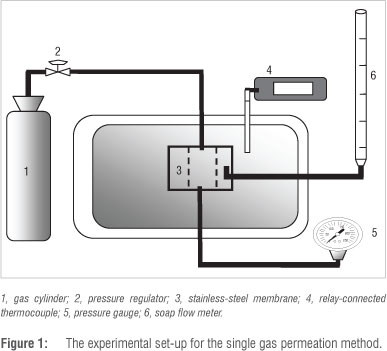
A continuous flow method was used to determine single gas permeation values for N2, CF4 and C3F6. The experimental set-up for this continuous flow method is shown in Figure 1. The membranes were sealed with o-rings in a membrane module made from stainless steel. The gas-tight permeation module was positioned vertically in an oven of which the temperature was electronically controlled by a relay-connected thermocouple. The transmembrane pressure was monitored by a pressure gauge and gas feed to the inner-tube side of the membrane was controlled by a pressure regulator. The permeate flow was measured by a soap flow meter at atmospheric pressure (0.87 bar).
The permeation flux (mol/m2.s) from each experiment was recorded as an average of five measurements over a period of 60 min to ensure that a steady rate had been reached. The total membrane surface area calculated was 3.06 x 10³ m2. This value was used for all calculations.
The ideal selectivities or permselectivities (PSi/j for gas i and gas j were defined as the single-component permeance ratio, at a given temperature and transmembrane pressure. The permselectivities were qualitatively compared to the Knudsen selectivities to evaluate the performance of each membrane. The Knudsen selectivity (PSk) is obtained by:

where M is the molar weight (g/mol) of the respective gas. Adsorption
We employed gravimetry to investigate the adsorption of N2, CF4 and C3F6 on the various materials used in the membranes. An isotherm accounting for adsorbate size, chemical dissociation and molecular interactions is shown by Equation 2:

in which s represents the dissociation parameter (-), Keq is the equilibrium constant (bar-1), u is the interaction energy between the adsorbed molecules (J), k is the Boltzmann constant (j/K), n is the number of active sites occupied by a single molecule (-) and T is the temperature (K). The equilibrium constant Keq = kœ exp(-ΔHads / RT), where kœ is a pre-exponential factor (g/gadsxbar), R is the universal gas constant (J/molxK), T is the temperature (K) and ΔH is the heat of adsorption (kJ/mol). In Equation 3:

q is the amount absorbed (g/gads) and qm is the maximum loading that can occur when complete coverage of the absorbed gas takes place (g/gads). The experimental data was fitted to Equation 2 to determine the qm for each gas/material combination. In this study, we ignored the dissociation parameter and the interaction energy, therefore s=1 and u=0 J.22
The thermogravimetric analysis (TGA) instrument was a TA Instruments thermogravimeter (Q50, New Castle, DE, USA). A sample of between 10 mg and 15 mg was placed in the sample cup and left for 24 h in the furnace at a temperature of 200 °C in a helium flow of 50 mL/min to remove adsorbed water.
The sample was then cooled under helium to room temperature, and then set to the experimental temperature. A pre-determined mixture of helium and adsorbate gas were fed to the TGA using the calibrated mass flow controllers with the total gas flow rate equal to 50 mL/min. The weight of the sample was recorded until equilibrium was reached. Subsequently, the composition of the gas mixture was adapted in order to measure the full isotherm in the 0-85 kPa range. The amount of gas adsorbed at each pressure was determined in order to obtain the isotherm.
Theoretical selectivities were calculated by the ratio of qm values of the C3F6 and CF4 adsorbed at each temperature according to:
where S is the molar selectivity with T the temperature (K), qmCFe the amount of C3F6 adsorbed (mol/gads) and qmCF the amount of CF4 adsorbed (mol/gads).
Results and discussion
Morphology
α-Alumina support
The most important advantage of the centrifugal casting technique for the manufacturing of ceramic membranes compared to the more traditional extrusion method is the smooth inside surface with minimal surface defects obtained (Figure 2), which is advantageous for the synthesis of a thin, continuous, defect-free separation layer.23

The sintered a-alumina tubes had inner and outer diameters of 0.0177 m and 0.0207 m, respectively. According to mercury porosimetry measurements, the porosity of the supports was 37%, and the average pore size was 167 nm.
From the cross-section view (Figure 3) it is clear that the smaller particles were situated near the inner surface (Figure 3a) while the larger particles settled at the outer surface (Figure 3b) during the centrifugal casting process, which resulted in a graded ceramic support structure.


MFI-coated ceramic membrane
From the top view of the MFI-coated membrane (Figure 4a), it is clear that the MFI covered the support surface completely, while the cross-section view (Figure 4b) shows that the MFI formed a closed, continuous zeolite layer of approximately 7 mm. The well-defined crystal edges signify a complete crystalline structure. Based on the XRD spectrum (Figure 5) and using the 2007 Relational Database, we confirmed the structure of the MFI zeolite.24


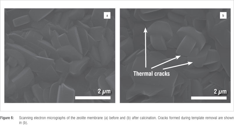
Although the support was completely covered (Figure 4), because of a thermal expansion mismatch between the bonded zeolite and the ceramic support, crack formation is frequently present with template removal during calcination, which is one of the main causes of non-zeolite pores.25 This phenomenon is clearly shown in the SEM images of an MFI-coated ceramic membrane before and after calcination, illustrated in Figure 6a and 6b, respectively. Another important aspect of inorganic membrane synthesis is reproducibility. Poor reproducibility is a problem commonly encountered with zeolite membranes.26
Teflon-coated ceramic membrane
The application of a polymer layer onto an inorganic support can be cumbersome when the concentration of the polymer solution and the dip-coating procedure are not optimised. According to the supplier, the Teflon AF 2400 had to be dissolved in an electronic liquid at a temperature of 70 °C or above. It was, however, imperative that no electronic liquid (FC-77) evaporated at elevated temperatures as this evaporation would have resulted in an increase in the concentration of the AF 2400 present in the mixture, which would have resulted in the deposition of AF 2400 onto the PTFE bottle.
To ensure the highest possible flux, we decided to determine the lowest possible polymer concentration that yielded a closed continuous layer using the dip-coating procedure described previously. It was found that concentrations below 0.5 wt% Teflon AF 2400 resulted in non-continuous layers with defects (determined with SEM), whereas concentrations at 0.5 wt% and above resulted in defect-free layers. For this reason, a concentration of 0.5 wt% was used for the synthesis of the Teflon-coated ceramic membrane as well as the composite ceramic membrane. The heat treatment which had been optimised to ensure attachment of the Teflon AF 2400 onto the inorganic material was used in the synthesis of both the composite ceramic membrane and the Teflon-coated ceramic membrane.
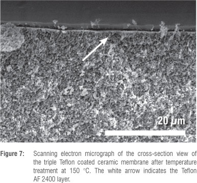
The continuous double or triple Teflon coated layers were approximately 2 jm and 2-3 jm thick, respectively, with limited penetration of the polymer phase into the underlying pores of the ceramic support membrane (Figure 7). From the top-view SEM images (not shown), it became clear that the Teflon layer completely covered the smooth ceramic surface, with no visible defects present.
Composite ceramic membrane
The top views of the Teflon-layered MFI membrane after 1-h treatments at various temperatures are shown in Figure 8a-d. The SEM assessments revealed that after treatment over a 1-h period at 100 °C, only slight penetration of the Teflon layer onto the underlying MFI zeolite occurred, as is visible in Figure 8a. Treatment at 150 °C (Figure 8b) resulted in improved penetration of the Teflon in-between individual MFI crystals. Once the temperature was increased to 200 °C (Figure 8c), bonds within the polymer structure started to break, which resulted in the appearance of the characteristic MFI zeolite shape underneath and led to the appearance of a few pinholes and tears in the overlying Teflon coating.27 The complete disintegration of the Teflon layer is clearly visible at 300 °C (Figure 8d) as pronounced tearing is apparent. At 340 °C, no Teflon was visible under SEM (image not shown).
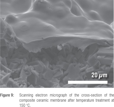
According to SEM results, the attachment treatment at 150 °C was optimal. A cross-section of the 150 °C-treated membrane is shown in Figure 9, and clearly shows the non-damaged Teflon layer. The penetration of the 3-4 mm thick Teflon layer in-between the zeolite crystals can be observed.
Single gas permeation
Before comparing the gas permeabilities of the various membrane types, the effect of the heat treatment used to attach the Teflon layer onto the MFI zeolite in the composite membrane was evaluated in terms of gas permeance values. The results are shown in Table 2.
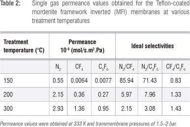
All membranes exhibited permeance values in the order of N2 > CF4 > C3F6, which can be directly related to the kinetic diameter of the molecules (N2 = 3.8 Å, CF4 = 4.7 Å, C3F6 ≈ 6.6 Å) with the exception of the membrane treated at 150 °C. The significant increase in permeance values for all gases for membranes treated above 150 °C is most likely as a result of the defects shown in the SEM images (Figure 8), which resulted in a decrease in selectivity with increasing temperature. However, this trend was not observed for the ideal selectivities of CF4/C3F6 for which ideal selectivities increased with increasing temperature. For a probable explanation of this phenomenon see the discussion surrounding the results obtained for the five different membranes (Figures 10 and 11).

The Teflon-coated MFI membrane manufactured at 150 °C was used for a comparison with the other synthesised membranes. The single gas permeance values for the various membranes synthesised in this study are summarised in Table 3.

As expected, the ceramic support (Membrane 1) without any layers yielded the highest permeance values for N2, followed by CF4 and then C3F6. This observation was expected considering the kinetic diameters of the gases and the pore size of the ceramic support. The calculated molar diameters of the gases according to molecular modelling were 0.168 nm, 0.268 nm and 0.552 nm for N2, CF4 and C3F6, respectively; these diameters are small compared to the 167-nm pore diameter of the support. Kinetic diameter values for N2 and CF4 reported in the literature are 0.36 nm and 0.47 nm, respectively.28,29 Permeance results were consistent with Knudsen diffusion.
The additional Teflon layers applied onto the ceramic support (Membranes 2a and 2b) resulted in an overall decrease in permeability compared to the ceramic support, with the triple Teflon coated ceramic having the lowest permeability, as expected given the increased thickness of the triple layer. Similarly to the ceramic support, a higher permeance for N2 than for CF4 and C3F6 was observed for both the double and triple Teflon coated ceramic membranes. As the N2/CF4 and N2/C3F6 permselectivities were larger than the permselectivities for the ceramic support and above Knudsen (Figure 10), the contribution of adsorption to the overall permeation through the membrane became more significant according to the solubility-diffusion model which is largely present when polymer membrane permeabilities are considered. This relation is given by

where P is the permeability coefficient (m3.m/m2.s.Pa), D is the diffusion coefficient (m2/s) and S is the solubility coefficient (Pa1).30 The significant decrease in permeance as a result of the addition of Teflon layers confirms that the Teflon layers were produced without significant defects.
The significant decrease in permeability of the MFI-coated ceramic (Membrane 3) compared to the ceramic support indicates the formation of an intergrown MFl layer. The preferential permeation of N2 compared to CF4 and C3F6 was also observed for the MFI-coated ceramic. The permselectivity for CF4/C3F6, although above Knudsen selectivity, is low when you consider that the C3F6 molecule is larger than the MFl zeolite pore sizes. This confirms the existence of non-zeolite pores, because the total measured permeance through the MFl zeolite membrane was the summation of the zeolite and non-zeolite (intercrystalline) permeance values. The existence of non-zeolite pores was the result of non-perfect intergrowth between individual crystals during synthesis5 and crack formation during template removal.
The considerable decrease in permeability of the composite ceramic membrane (Membrane 4) compared to the other manufactured membranes indicates that a dense, defect-free membrane had been obtained. The N2 permeation is the largest with the C3F6 permeation through the composite ceramic membrane being larger than that of CF4. It is expected that the diffusion coefficient of CF4 should be larger than that of C3F6 as the diffusion characteristics are usually determined by the membrane properties and the size of the permeant species. The considerable solubility of C3F6 compared to CF4 in the Teflon membrane resulted in a larger overall C3F6 permeability, which can be attributed to the interaction between the membrane and the permeate.31 The larger gas permeation of C3F6 compared to CF4 is consistent with explanations given by Wijmans and Baker30 for permeation of n-alkanes through silicone rubber membranes. According to the authors, the saturation vapour pressure and the diffusion coefficient both decrease with increasing molecular weight of the permeate creating competing effects on the permeability coefficient. The permeability coefficient (PiG) is given by

where Dj is the diffusion coefficient, yj is the activity coefficient linking concentration with activity, yj(mj is the activity of component j in the membrane phase and pj(sllj is the saturation vapour pressure. For molecules up to a weight of 100, permeability generally increases with increasing molecular weight because pj(salj is the dominant term. Thus pj(silj decreases, which results in an increase in permeability. For molecules with molecular weights above 100, the diffusion coefficient term becomes more dominant, and permeabilities decrease with increasing molecular weight of the permeate. This trend is clearly illustrated for permeation of simple alkanes in silicone rubber membranes. Permeation increased from CH4 to C5H12 and permeation decreased again as molecular weight increased for molecules heavier than C5H12. However, the permeation of C10H22 was still equivalent to C3H8. In our study the larger permeability of C3F6 compared to CF4 is equivalent to the permeability increase from CH4 to C5H12 in the study of Wiljmans and Baker30.
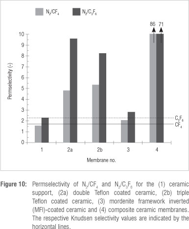
We can now consider the ideal selectivities of the five membranes. According to the ideal selectivity values (Figures 10 and 11), the ceramic support (Membrane 1) yielded selectivities in the range of the Knudsen selectivity for N2/CF4, N2/C3F6 and CF4/C3F6. This was expected for a typical microfiltration type membrane (pore size = 167 nm).
The ideal selectivities for the double (Membrane 2a) and triple (Membrane 2b) Teflon coated ceramic membranes were above Knudsen selectivities for N2/CF4 and N2/C3F6. The lower CF4 and C3F6 permeabilities compared to N2 were as a result of the high saturation vapour pressure of CF4 and C3F6 compared to N2, according to Equation 6. According to Figure 11, CF4/C3F6 ideal selectivities were above Knudsen with a preferential permeation of CF4. This finding is in disagreement with those of Wijmans and Baker30 for permeation of n-alkanes through silicone rubber membranes, in which a higher permeation of C3F6 was found. This discrepancy could be a result of defects or cracks in the Teflon layers that were not observed under SEM. In the presence of cracks, Knudsen diffusion, with a preferential transport of CF4, is therefore the most likely mechanism of transport for the Teflon-coated ceramic.
The MFI-coated ceramic (Membrane 3) showed some degree of molecular sieving with selectivities slightly above Knudsen. When the size of the C3F6 molecule is considered in relation to the pore size of the MFI zeolite and the ideal selectivities obtained with only the ceramic support, it is evident that the contribution of non-zeolite pores to the total permeation is considerable.
The effect of combining a Teflon layer and a MFI zeolite (Membrane 4) is clearly seen in the dramatic increase in selectivities for N2/CF4 and N2/C3F6 for the composite ceramic membrane compared to the Teflon- or zeolite-only ceramic. The increased N2/CF4 and N2/C3F6 selectivities were because of a dense defect-free Teflon layer which effectively sealed the non-zeolite pores. The influence of the higher saturation pressures of CF4 and C3F6 on the permeability coefficient was amplified by the defect-free Teflon layer. The preferential permeation of C3F6 over CF4 confirms this statement and is in agreement with the findings of Wijmans and Baker30. These results again confirm the existence of defects and/or cracks in both the Teflon-coated ceramic as well as the MFI-coated ceramic membranes. This finding then also helps explain the results observed for the heat-treatment variations of the composite membrane (Table 2). At 150 °C, the Teflon layer is defect free, thus the solubility and permeance of C3F6 is increased. However, at 200 °C and above, the Teflon layer cracks which results in gas permeation through the zeolite layer only; in addition, it has been shown (Figure 10 and 11) that the zeolite layer alone also contains defects, hence the increased permeance of the smaller CF4 at higher Teflon treatment temperatures.
Table 4 shows permeability values obtained from the literature relating to the gases evaluated in this study for polymer and zeolite membranes. Because the literature available on CxFy is limited, studies on CxHy were included for comparison.
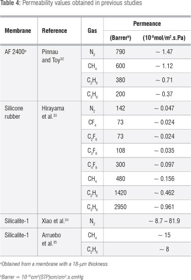
Our permeability studies of gases through Teflon AF 2400 membranes were conducted according to those in the literature.32 Permeabilities decreased with increasing carbon chain length of the hydrocarbons.30 Larger permeabilities for longer carbon chain length components33 of fluorocarbons and hydrocarbons through silicone rubber membranes (102 um) correlates with the findings of Wijmans and Baker30. Increased permeability with increased molecular size is a result of the higher solubility of polymer membranes.33 The permeance values obtained in the study of Pinnau and Toy32 were notably higher than those obtained in the study by Hirayama et al.33, which may be because of the thinner membrane used by Pinnau and Toy32. A decrease in permeability with increased gas molecular size was observed for the double and triple Teflon coated ceramic membrane in this study, similarly to the AF 2400 membrane of Pinnau and Toy32. The silicon rubber membrane characterised with hydrocarbon and fluorocarbon gases33 showed similar permeability trends to our composite ceramic membrane. The permeabilities increased with increasing carbon chain length. The composite ceramic membrane had a superior permeability with regard to N2, but a considerably lower CF4 permeability, resulting in a higher N2/CF4 permselectivity. Although C3F8 and not C3F6 was investigated by Hirayama et al.33, similar results were anticipated because of the same number of carbons present in the molecules and therefore a lower N2/C3F6 permselectivity was expected for their silicon rubber membrane compared to our composite ceramic membrane. However, the CF4/C3F6 permselectivity found in our study is comparable with the CF4/C3F8 permselectivity determined by Hirayama et al.33
According to studies in the literature on silicalite-1,34,35 the permeabilities of fluorocarbons through the MFI-coated ceramic evaluated in this study were low compared to the permeabilities of hydrocarbons using the same zeolite. However, as reported in previous studies, we showed preferential permeation of the smaller molecules through the MFI membrane as a result of molecular sieving. The permselectivities obtained by Arruebo et al.35 were, however, higher - a result which was unexpected as permselectivity typically increases as permeability decreases. This observation again indicates the presence of defects in these membranes.
Adsorption
To explain gas permeance values through MFI (silicalite-1) and the composite membrane, it is essential to elaborate on the adsorption data. The zeolite crystals investigated were pure silicalite-1 crystals. Their synthesis was conducted exactly as described for the MFI-coated ceramic membrane but without the addition of the a-alumina support.
The control adsorption study showed that no noticeable amounts of N2, CF4 or C3F6 adsorbed onto the a-alumina. Adsorption of C3F6 onto silicalite-1 was higher than the adsorption of CF4 (Figure 12), while N2 adsorption was too low to measure. Higher adsorption amounts for longer carbon chain length compounds are commonly reported in the literature36,37 for hydrocarbons adsorbed onto molecular sieves. The same observation was reported by Ahn et al.38 for fluorocarbon gases, that is, the longer chain carbon compound in their study (C2F6) was adsorbed in larger amounts than was CF4 onto zeolite 13X over the entire pressure and temperature range.
The adsorption amount in this study decreased with increasing temperature as expected.38 There was an increase in adsorption with increased pressure for both CF4 and C3F6. Theoretical selectivities (based on adsorption) increase with increasing temperature. The calculated selectivities (at 0.85 bar) were 5, 10, 11 and 15 at 313 K, 333 K, 353 K and 373 K, respectively. For silicalite-1, the maximum theoretical selectivity of 15 (mol to mol ratio in favour of C3F6) was obtained at 373 K when the amounts of CF4 and C3F6 adsorbed at 0.85 bar were used in the calculation.
The only noticeable amount of CF4 adsorption onto the Teflon was observed at 293 K and 0.85 kPa (results not shown). The maximum adsorbed amount recorded was 0.0024 g/gabs (0.27 x 10⁻⁴ mol). The adsorption of N2 onto Teflon AF 2400 was also investigated, but no noticeable adsorption was obtained. The adsorption isotherms of C3F6 on Teflon AF 2400 are shown in Figure 13. Isotherms were obtained at temperatures ranging from 303 K to 333 K. A theoretical selectivity of 26 in favour of C3F6 was calculated in terms of the maximum molar amount of gas adsorbed at 293 K for CF4 and C3F6 onto Teflon.

It is well known that the solubility of a gas in a polymer structure is related to the condensability of the gas. The condensability is a function of the critical temperature which is in turn related to the diameter of the gas molecule.39 The critical temperatures of N2, CF4 and C3F6 are 129.2 K,40 227.65 K,43 and 359.35 K,40 respectively. It is obvious that the C3F6 molecule is larger than the CF4 molecule,42 while the N2 molecule is the smallest. The calculated diameters of the gases according to molecular modelling were 0.168 nm, 0.268 nm and 0.552 nm for N2, CF4 and C3F6, respectively. The reason C3F6 was preferentially adsorbed, both for the zeolite and the Teflon AF 2400 membranes, is therefore because of its higher condensability, and thus solubility, in Teflon.
By fitting the Langmuir isotherm to the adsorption data, the maximum adsorption at each temperature was obtained (Figures 12 and 13). The results are shown in Table 5. The adsorption results explain why a higher permeability through the composite ceramic membrane was obtained for C3F6 than for CF4. The contribution of the solubility effect was, however, not significant enough when the Teflon-coated ceramic membrane was considered because of the defects present, which resulted in the contribution of the diffusion coefficient term being favoured over the permeability.

Conclusions
One paramount factor that determines the performance of inorganic membranes for gas separation is the number of defects present in the selective layer. For continuous layer zeolite membranes, defects result from intercrystalline slits11 and crack formation25 during synthesis and template removal. The prevention or 'repair' of defects is essential to obtain high ideal selectivity values.
We thus developed a composite ceramic membrane consisting of a ceramic support structure, an MFI intermediate zeolite layer and a Teflon AF 2400 top layer for separation of N2, CF4 and C3F6. The synthesis of the Teflon layer was included with the aim of closure of possible defects present in the separation layer forcing the gas molecules to follow the path through the zeolite pores. In the evaluation, the composite membrane was compared with a ceramic membrane, an MFI-coated ceramic membrane and a Teflon-coated ceramic membrane using single gas permeation experiments. Adsorption experiments were performed on materials present in the membrane structures to clarify the results obtained.
The two best performing membranes according to N2/CF4 and N2/C3F6 ideal selectivities were the Teflon-coated ceramic membrane and the composite ceramic membrane. Although the top layer in both membranes was similar, the presence of the MFI zeolite in the composite ceramic membrane resulted in higher permselectivities. For the composite ceramic membrane, ideal selectivities of 86 and 71 were obtained for N2/CF4 and N2/C3F6, respectively, compared to 5.5 and 8 for the Teflon-coated ceramic. CF4/C3F6 selectivities ranged from 0.85 to 2 with C3F6 permeating faster though the composite ceramic membrane.
The higher adsorption of C3F6 onto Teflon AF 2400, compared with CF4, resulted in a considerable contribution to the extent of permeation for the composite ceramic membrane. The sealing effect of the zeolite layer by the Teflon layer is, however, the reason for the large N2/CF4 and N2/C3F6 selectivities obtained.
Acknowledgements
We acknowledge the financial assistance of the Innovation Fund of South Africa (Project T50021), a separate business unit of the Department of Science and Technology, and the South African Nuclear Energy Corporation. We thank Dr L. Tiedt (NWU, South Africa) for the SEM images and Mr J. Kroeze and Mr A. Brock (Technical Advisory, NWU, South Africa) for the manufacture of the membrane reactors and the permeation set-up. We also acknowledge the contribution of Dr Klaus-Victor Peinemann (GKSS Research Centre, Germany) towards the application of a polymer layer for sealing of defects present in a zeolite membrane.
Authors' contributions
H.B. performed the experiments and wrote the paper. H.M.K. supervised the project and assisted with the writing of the paper.
References
1. Singh A, Koros WJ. Significance of entropic selectivity for advanced gas separation membranes. Ind Eng Chem Res. 1996;35:1231-1234. http://dx.doi.org/10.1021/ie950559l
2. Bowen TC, Noble RD, Falconer JL. Fundamentals and applications of pervaporation through zeolite membranes. J Membr Sci. 2004;245:1-33. http://dx.doi.org/10.1016/j.memsci.2004.06.059
3. Chung T, Jiang LY Li Y Kulprathipanja S. Mixed matrix membranes (MMMs) comprising organic polymers with dispersed inorganic fillers for gas separation. Prog Polym Sci. 2007;32:483-507. http://dx.doi.org/10.1016/j.progpolymsci.2007.01.008
4. Caro J, Noack M. Zeolite membranes - Recent developments and progress. Microporous Mesoporous Mater. 2008;115:215-233. http://dx.doi.org/10.1016/j.micromeso.2008.03.008
5. Yan Y Davis ME, Gavalas GR. Preparation of highly selective zeolite ZSM-5 membranes by a post-synthetic coking treatment. J Membr Sci.1997;123:95-103. http://dx.doi.org/10.1016/S0376-7388(96)00206-2 [ Links ]
6. Hedlund J, Jareman F, Bons A, Anthonis M. A masking technique for high quality MFI membranes. J Membr Sci. 2003;222:163-179. http://dx.doi.org/10.1016/S0376-7388(03)00285-0
7. Miachon S, Landrivon E, Aouine M, Sun Y Kumakiri I, Li Y et al. Nanocomposite MFI-alumina membranes via pore-plugging synthesis: Preparation and morphological characterisation. J Membr Sci. 2006;281:228-238. http://dx.doi.org/10.1016/j.memsci.2006.03.036 [ Links ]
8. Nair S, Tsapatsis M. Synthesis and properties of zeolitic membranes. In: Auerbach SM, Carrado KA, Dutta PK, editors. Handbook of zeolite science and technology. New York: Marcel Dekker; 2003. p. 867-919. http://dx.doi.org/10.1201/9780203911167.ch17 [ Links ]
9. Van Niekerk A, Zah J, Breytenbach JC, Krieg HM. Direct crystallisation of a hydroxysodalite membrane without seeding using a conventional oven. J Membr Sci. 2007;300:156-164. http://dx.doi.org/10.1016/j.memsci.2007.05.021
10. Sano T, Ejiri S, Yamada K, Kawakami Y, Yanagishita H. Separation of acetic acid-water mixtures by pervaporation through silicalite membranes. J Membr Sci. 1997;123:225-233. http://dx.doi.org/10.1016/S0376-7388(96)00224-4
11. Lee JB, Funke HH, Noble RD, Falconer JL. Adsorption-induced expansion of defects in MFI membranes. J Membr Sci. 2009;341:238-245. http://dx.doi.org/10.1016/j.memsci.2009.06.011
12. Noack M, Kölsch P Dittmar A, Stöhr M, Georgi G, Eckelt R, et al. Effect of crystal intergrowth supporting substance (ISS) on the permeation properties of MFI membranes with enhanced Al-content. Microporous Mesoporous Mater. 2006;97:88-96. http://dx.doi.org/10.1016/j.micromeso.2006.07.031 [ Links ]
13. Kanezashi M, O'Brien J, Lin YS. Template-free synthesis of MFI-type zeolite membranes: Permeation characteristics and thermal stability improvement of membrane structure. J Membr Sci. 2006;286:213-222. http://dx.doi.org/10.1016/j.memsci.2006.09.038
14. Shieh J, Chung T, Paul DR. Study on multi-layer composite hollow fiber membranes for gas separation. Chem Eng Sci. 1999;54:675-684. http://dx.doi.org/10.1016/S0009-2509(98)00256-5
15. Baker RW. Membrane technology and applications. 2nd ed. West Sussex: Wiley; 2004. p. 126,313. [ Links ]
16. Merkel TC, Bondar V Nagai K, Freeman BD, Yampolskii YP Gas sorption, diffusion, and permeation in poly(2,2-bis(trifluoromethyl)-4,5-difluoro-1,3-dioxole co-tetrafluoroethylene). Macromolecules. 1999;32:8427-8440. http://dx.doi.or/10.1021/ma990685r [ Links ]
17. Li S. Jinjin D. Improvement of hydrophobic properties of silk and cotton by hexafluoropropene plasma treatment. Appl Surf Sci. 2007;253:5051-5055. http://dx.doi.org/10.1016/j.apsusc.2006.11.027
18. Hinchliffe AB, Porter KE. A comparison of membrane separation and distillation. Chem Eng Res Des. 2000;78:255-268. http://dx.doi.org/10.1205/026387600527121
19. Bissett H, Zah J, Krieg HM. Manufacture and optimization of tubular ceramic membrane supports. Powder Technol. 2008;181:57-66. http://dx.doi.org/10.1016/j.powtec.2007.06.005
20. Hofman-Züter J. Chemical and thermal stability of modified mesoporous ceramic membranes [PhD thesis]. Twente, Netherlands: University of Twente; 2003. p. 211. [ Links ]
21. Van Niekerk A. Direct crystallization of hydroxysodalite and MFI membranes on a-alumina support [thesis]. Potchefstroom: North-West University; 2005. p. 63-64. [ Links ]
22. Seader JD, Henley EJ. Separation process principles. New York: John Wiley & Sons; 1998. [ Links ]
23. Zivkovic T. Thin supported silica membranes [PhD thesis]. Twente, Netherlands: University of Twente; 2007. p. 5. [ Links ]
24. Treacy MMJ, Higgins JB. Collection of simulated XRD power patterns for zeolites. 4th ed. Amsterdam: Elsevier; 2001. [ Links ]
25. Gualtieri ML, Andersson C, Jareman F, Hedlund J, Gualtieri AF, Leoni M, et al. Crack formation in a-alumina supported MFI zeolite membranes studied by in situ high temperature synchrotron powder diffraction. J Membr Sci. 2007;290:95-104. http://dx.doi.org/10.1016/j.memsci.2006.12.018 [ Links ]
26. McLeary EE, Jansen JC, Kapteijn F. Zeolite based films, membranes and membrane reactors: Progress and prospects. Microporous Mesoporous Mater. 2006;90:198-220. http://dx.doi.org/10.1016/j.micromeso.2005.10.050
27. LI NN, Fane AG, Ho WSW, Matsuura T. Advanced membrane technology. New Jersey: John WIley and Sons; 2008. p. 650. [ Links ]
28. Baker RW. Membrane technology and applications. West Sussex, McGraw Hill; 2000. p. 531. [ Links ]
29. Albrecht E, Baum G, Bellunato T, Bressan A, Torre SD, D'Ambrosio C, et al. VUV absorbing vapours in n-perfluorocarbons, Nucl Instrum Methods Phys Res A. 2003;510:262-272. http://dx.doi.org/10.1016/S0168-9002(03)01867-9 [ Links ]
30. Wijmans JG, Baker RW. The solution-diffusion model: A review. J Membr Sci. 1995;107:1-21. http://dx.doi.org/10.1016/0376-7388(95)00102-I
31. Stern SA. Polymers for gas separations: The next decade. J Membr Sci. 1994;94:1-65. http://dx.doi.org/10.1016/0376-7388(94)00141-3
32. Pinnau I, Toy LG. Gas and vapor transport properties of amorphous perfluorinated copolymer membranes based on 2,2-bistrifluoromethyl-4,5-difluoro-1,3-dioxole/tetrafluoroethylene. J Membr Sci. 1996;109:125-133. http://dx.doi.org/10.1016/0376-7388(95)00193-X
33. Hirayama Y, Tanihara N, Kusuki Y, Kase Y, Haraya K, Okamoto K. Permeation properties to hydrocarbons, perfluorocarbons and chlorofluorocarbons of cross-linked membranes of polymethacrylates with poly(ethylene oxide) and perfluorononyl moieties. J Membr Sci. 1999;163:373-381. http://dx.doi.org/10.1016/S0376-7388(99)00177-5
34. Xiao W, Yang J, Lu J, Wang J. A novel method to synthesise high performance silicalite-1 membrane. Separ Purif Tech. 2009;67:58-63. http://dx.doi.org/10.1016/j.seppur.2009.03.007
35. Arruebo M, Coronas J, Mene'ndez M, Santamari'a J. Separation of hydrocarbons from natural gas using silicalite membranes. Separ Purif Tech. 2001;25:275-286. http://dx.doi.org/10.1016/S1383-5866(01)00054-5
36. Peng J, Ban H, Zhang X, Song L, Sun Z. Binary adsorption equilibrium of propylene and ethylene on silicalite-1: Prediction and experiment. Chem Phys Lett. 2005;401:94-98. http://dx.doi.org/10.1016/j.cplett.2004.11.036
37. Triebe RW, Tezel FH, Khulbe KC. Adsorption of methane, ethane and ethylene on molecular sieve zeolites. Gas Sep Purif. 1996;10:81-84. http://dx.doi.org/10.1016/0950-4214(95)00016-X
38. Ahn N, Kang S, Min B, Suh S. Adsorption Isotherms of tetrafluoromethane and hexafluoroethane on various adsorbents. J Chem Eng Data. 2006;51:451-456. http://dx.doi.org/10.1021/je0503756
39. Dingemans M, Dewulf J, Kumar A, Van Langenhove H. Solubility of volatile organic compounds in polymers: Effect of polymer type and processing. J Membr Sci. 2008;312:107-114. http://dx.doi.org/10.1016/j.memsci.2007.12.042
40. MSDS. Hexafluoropropene (R1216) safety data sheet. Air Liquide; 2005. [ Links ]
41. Stapf S, Han S. NMR imaging in chemical engineering. Weinheim Wiley-VCH;2006. p. 310. [ Links ]
42. Grazian G. On superhydrophobicity of tetrafluoromethane. Chem Phys Lett. 2008;460:470-473. http://dx.doi.org/10.1016/j.cplett.2008.06.057
 Correspondence:
Her tzog Bissett
PO Box 582
Pretoria 0001, South Africa
Email: Hertzog.bissett@necsa.co.za
Received: 01 Aug. 2012
Revised: 08 Feb. 2013
Accepted: 03 Apr. 2013

