


Services on Demand
Article
 English (pdf)
 Article in xml format
 Article references
Indicators

Related links
-
 Cited by Google
 -
 Similars in Google
Share

 Permalink
South African Journal of Science
On-line version ISSN 1996-7489
Print version ISSN 0038-2353
S. Afr. j. sci. vol.108 n.7-8 Pretoria Jan. 2012
RESEARCH ARTICLE
Sensitivity versus polarisation in multilayer optical thin film design
Efrem K. EjiguI; Beartys M. LacquetII
IDepartment of Electrical and Electronics Engineering Science, University of Johannesburg, Johannesburg, South Africa
IIFaculty of Engineering and the Built Environment, University of the Witwatersrand, Johannesburg, South Africa
ABSTRACT
The design of a polarised optical filter is more complicated than that of a filter where the polarisation effect does not exist (at a normal angle of incidence). An error in the optical parameters, such as the physical thickness or refractive index of a layer, results in a change in the spectral performance of the multilayer structure. The correlation between error sensitivity and the polarisation effect of light in structures designed at an oblique angle was investigated. To illustrate the correlation, a perpendicular (S) and parallel (P) polarised beam splitter, at 0.9818 ìéôé central wavelength, designed by genetic algorithm, was used. The beam splitter changes its state of polarisation according to the error in thickness simultaneously induced in each of the layers. The error was calculated by optimising the original design. The observation of the change of the state of polarisation as a result of error sensitivity leads to a different method of designing pure S-polarised or P-polarised optical filters.
Introduction
In the design and manufacture of a multilayer structure, the sensitivity of layers to error needs to be given special consideration. Errors in the optical parameters, such as thickness and refractive index, can have various causes. The sensitivity of the layers to the induced error results in a change in the spectral performance of the structure as a result of a change in the interference pattern at the layer interfaces where the error is induced. The error effect on a multilayer structure designed at an oblique angle can be intense as a result of polarisation. A light incident at an oblique angle has two sets of beams: S-polarised and P-polarised beams. Because of a difference in the phase shift in the S-polarised and P-polarised beams, the effect of the error seems noticeable in structures designed at an oblique angle of incidence.1
We analysed the error sensitivity of a multilayer structure designed at an oblique angle of incidence. The error sensitivity of each of the layers of a multilayer structure gives information on the effect it has on the change in the optical behaviour of S and P components of the beam. The error-induced behavioural change of S-polarised and P-polarised components leads to a change in the state of polarisation of the structure as a system. This observation gives an important clue to the method of designing a pure S-polarised multilayer structure.
Theoretical background
Sensitivity analysis
A thin film structure with n number of layers can be represented by a 2x2 matrix, which contains the optical parameters (refractive index, physical thickness, etc.) of a thin film.2,3,4,5
Reflectance and transmittance of an optical filter can be calculated by using the 2x2 matrix of the multilayer structure surrounded by two substrates.3 For this study, a Matlab code computer program,6 which calculates reflectance and transmittance, was prepared using the matrix representation method of a multilayer structure.
Sensitivity is often related to errors that are induced during the manufacturing process, as a result of human or instrumental error, as one loses control of precision.4,7 Hence, it is useful to study the sensitivity factor, as it has a significant effect on the final spectral performance of the manufactured thin film. The optical thin film parameters that are prone to error are the physical thickness and the refractive index. A sensitivity study helps to reveal the tolerance level of the thickness or refractive index of each layer.8 By investigating the sensitivity, it is possible to see whether the design developed is manufacturable in the existing depositing conditions. Based on the concept of sensitivity, it is possible to induce errors in one of the parameters deliberately and adjust the design to obtain a desired spectral performance. In this study, we exploited the concept of sensitivity in converting an S-polarised design into a P-polarised one and vice versa. This conversion can be done by introducing a random change to all the layers simultaneously.
Using Beumeister's sensitivity analysis method, it is possible to analyse the sensitivity effect of only one layer at a time.4,8 One-layer-at-a-time variation involves a partial derivative of reflectance. The partial derivative of the matrix with respect to quarter wave thickness can be evaluated as in Thelen8.
The sensitivity of the whole system, as a result of parameter variation in a single layer, can be calculated by the derivative of the reflectance over a desired spectral range.5,8,9 The result gives a good indication of how the spectral performance is affected by a parameter change. If the parameter involved is simultaneously changed in all the layers, the effect will be high and the result can be a complete change of the spectral performance.
It is important to have a different form of analysis if we are interested in simultaneously changing the parameter in all the layers. For this study the method used was slightly different. Firstly, the variation in thickness needed was determined. Secondly, by simultaneously adjusting the thickness of each of the layers with the determined variation, the polarisation state of the design was changed. The determination of the exact thickness variation values appropriate for each layer can be rather difficult, but with the help of the optimisation computer program developed in Matlab code using the Matlab optimisation tool box, the difficulty can be minimised.10
For this study, three computer programs were developed. The first program calculated the transmittance, reflectance and merit value of the multilayer structure.11,12 The second program is a classical optimisation program that calls programs from the Matlab optimisation toolbox and the developed program that calculates merit values. The third program is a genetic algorithm program that calls programs from the genetic algorithm tool box6,13,14,15,16 and the program that calculates merit values. An original design is prepared using the genetic algorithm based program. The result of the original design is optimised using the classical optimisation based program.
Simultaneous variation of thickness or refractive index needs a different kind of treatment. We investigated a different way of varying all the layers simultaneously, resulting in the change of the state of polarisation. The calculation of thickness variation involves the optimisation of the original design. For instance, the original S-polarised design undergoes P-polarised optimisation to obtain a second set of parameters. The variation between the original and the second set is then determined and used as the variation in thickness of each layer. When all the layers of the original design are simultaneously subjected to this variation, the design changes its state of polarisation.
Results and discussion
To illustrate the method of designing polarised filters using the concept of sensitivity, a genetic algorithm designed beam splitter at an oblique angle of incidence was considered. Two 50/50 (percentage transmittance/percentage reflectance) beam splitters were designed with the following characteristics: a central wavelength of 0.9818 ìm, a bandwidth of 0.2 ìéç, an angle of incidence of 45°, and surrounding substrates with a refractive index value of 1.46. The first original design was the S-wave beam splitter with a thickness of 24.5072 ìm (Figure 1) and the second original design was a P-wave beam splitter with a thickness of 20.3629 ìém (Figure 2). In the genetic algorithm system, the physical thickness is used as a variable and allowed to vary within the boundaries of 0.9818 ìm and 0 ìm. The refractive index is not allowed to vary because the optimisation is conducted on only one of the parameters. The design consists of two materials - one with a high refractive index (H) and one with a low refractive index (L) - in alternating layers with a structure of HLHL. The two materials used in the designs were SOxNy materials with refractive index values of 3.2 (H) and 1.7 (L). The optimisation was run for 15 000 generations.
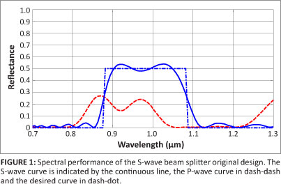
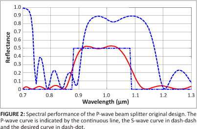
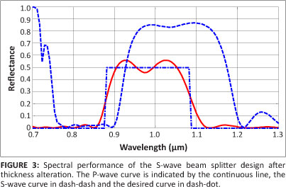
Figure 1 shows that the S-wave was split in a 50/50 proportion while the P-wave was split in an 80/20 proportion. In a design using a genetic algorithm, the program affects only the S-wave and does not control the P-wave. To study the effect of sensitivity, the thickness of all layers of the original design need to be altered simultaneously. The effect of the alteration results in the spectral behaviour change of the original design. This result is shown in Figure 3, in which the P-wave was split in a 50/50 proportion, whereas 80% of the S-wave was reflected. It can be seen here that the S-wave beam splitter design was changed into a P-wave beam splitter as a result of the sensitivity of the original design to the induced thickness errors.
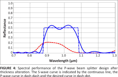
The spectral performance of the P-wave beam splitter original design is shown in Figure 2. The P-wave was split in a 50/50 proportion and almost 85% of the S-wave was reflected. This design is intended to control only the P-wave, which is why we did not see any control over the reflectance of the S-wave. Each layer in this design is subjected to a simultaneous alteration. The alteration results in the complete change of the optical behaviour of the original design in the same fashion as the first design does. The changed spectral performance is shown in Figure 4. The S-wave was split in a 50/50 proportion and the P-wave in an 80/20 proportion. When studying the original design of the P-wave and the resulting design after thickness alteration, it could be seen that the P-wave beam splitter had been transformed into an S-wave beam splitter.
It is important to know that neither of the two original designs purely polarise the S-wave or P-wave, but are intended to split the S-wave or P-wave into a 50/50 proportion, depending on the design. For instance, the S-wave beam splitter design is only intended to control the S-wave in a 50/50 proportion while the P-wave is uncontrolled. The designs, after undergoing thickness adjustment, change their spectral behaviour depending on their sensitivity to error. Any design will react to an error in any of the parameters by changing the spectral behaviour. The two examples illustrate the concept of sensitivity in the design of S-polarised or P-polarised beam splitters. This concept is one we used in the process of finally obtaining a pure polariser.
The spectral performance of a beam splitter that splits the P-wave into a 50/50 proportion is illustrated in Figure 3. It results from the thickness adjustment of the S-wave original design. The spectral performance of a beam splitter that splits the S-wave into a 50/50 proportion results from the thickness adjustment of the P-wave original design and is shown in Figure 4.
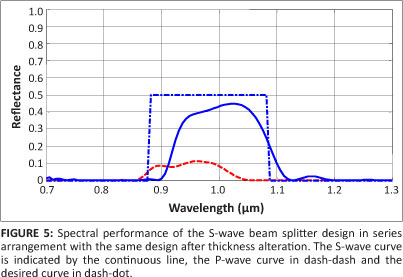
We have also shown that a relatively pure S-wave beam splitter can be obtained when the beam splitter of the original design, either the S-wave or the P-wave, and the designs obtained after thickness alteration are placed in series.1 The reflectance of a thin film that is constructed with a series-order arrangement of the first original design with its adjusted design is illustrated in Figure 5. It is possible to see that the P-wave was almost 95% transmitted, whereas the S-wave was split in a 55/45 proportion. Although the S-wave was not split in an exact 50/50 proportion, the 55/45 result is promising.
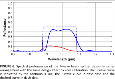
The overall reflectance of a thin film constructed with a series-order arrangement of the P-wave original design with its adjusted design is shown in Figure 6. The S-wave was split close in an almost 50/50 proportion and the P-wave was 95% transmitted. It is very interesting to see that this result is far better than the previous one (Figure 5) when the rejection region is analysed. Hence, a better, pure S-wave polarised beam splitter can be constructed using the P-wave original design and its adjusted design.
It also is interesting to see from the results that the concept of sensitivity is a powerful tool in understanding the factor responsible for the polarisation state change of a thin film design. Sensitivity is an important factor in the design of a pure polariser. This work can be extended to investigate the effect of refractive index parameter variation, but we do not expect the results would be as promising as those obtained from physical thickness parameter alteration.
Conclusion
We have successfully related the concept of sensitivity to the design of a polarised multilayer structure. It is important for a designer to control each layer's sensitivity to parameter error. The importance of considering the sensitivity effect, when preparing a design, is demonstrated in the design of the S-wave and P-wave beam splitter. The change in the polarisation state of a design, from an error deliberately induced, illustrates the use of the concept of sensitivity in designing polarisers. The concept of sensitivity is also demonstrated when a pure S-polarised beam splitter is designed. The findings of this study can be used in the design of pure polarised optical filters for optical communication applications.
Acknowledgements
We would like to thank the Department of Electrical and Electronics Engineering Science in the Faculty of Engineering and the Built Environment at the University of Johannesburg, the National Research Foundation (South Africa), and the Technology and Human Resources for Industry Programme for funding the research.
Competing interests
We declare that we have no financial or personal relationships which may have inappropriately influenced us in writing this paper.
Authors' contributions
E.K.E. performed the work and B.M.L. supervised the work.
References
1. Mohammed B, Mohammed Z. Chebychev response of thin film optical filters. Opt Rev. 2000;7:341-347. http://dx.doi.org/10.1007/s10043-000-0341-1 [ Links ]
2. Dobrowolski J. Versatile computer program for absorbing optical thin film systems. Appl Optics. 1981;20:74-81. http://dx.doi.org/10.1364/AO.20.000074, PMid:20309069 [ Links ]
3. Rabinovitch K, Pagis A. Polarisation effects in multilayer dielectric thin films. Opt Acta. 1974;21:963-980. http://dx.doi.org/10.1080/713818869 [ Links ]
4. Demichelis F, Ferrari G, Minetti-Mezzetti E, Perotto W. Refining method for the design of multilayer stacks. Appl Optics. 1982;21:1854-1858. http://dx.doi.org/10.1364/AO.21.001854, PMid:20389951 [ Links ]
5. Michielssen E, Ranjithan S, Mittra R. Optimal multilayer filter design using real coded genetic algorithms. IEE Proc J. 1992;139:413-420. [ Links ]
6. Matlab program and optimisation tool box. Version 7.0. Novi, MI: MathWorks; 2007. Available from: http://www.mathworks.com/web_downloads [ Links ]
7. Macleod HA. Thin-film optical filters. New York: Elsevier, 1969; p. 222-246. [ Links ]
8. Thelen A. Design of optical interference coatings. New York: McGraw-Hill, 1989; p. 219-235. [ Links ]
9. Heather L. Computer-aided techniques of the design of multilayer filters. Bristol: Adam Hilger, 1981; p. 143-164. [ Links ]
10. Southwell WH. Coating design using very thin high and low index layers. Appl Optics.1985;24:457-460. http://dx.doi.org/10.1364/AO.24.000457, PMid:18216968 [ Links ]
11. Dobrowolski J, Ho FC, Belkind A, Koss VA. Merit functions for more effective thin film calculations. Appl Optics. 1989;28:2824-2831. http://dx.doi.org/10.1364/AO.28.002824, PMid:20555608 [ Links ]
12. Dobrowolski J. Subtractive method of optical thin-film interference filters design. Appl Optics. 1973;12:1885-1893. http://dx.doi.org/10.1364/AO.12.001885, PMid:20125626 [ Links ]
13. Baumeister P. Design of multilayer filters by successive approximations. J Opt Soc Am. 1958;48:955-958. http://dx.doi.org/10.1364/JOSA.48.000955 [ Links ]
14. Baumeister P. Methods of altering the characteristics of a multilayer stack. J Opt Soc Am. 1962;52:1149-1152. http://dx.doi.org/10.1364/JOSA.52.001149 [ Links ]
15. Ejigu EK, Lacquet BM. Design of polarised and non-polarised edge filters using genetic algorithm. J Opt. 2010;12(3):035401. http://dx.doi.org/10.1088/2040-8978/12/3/035401 [ Links ]
16. Houck C, Jones J, Kay M. The genetic algorithm optimisation toolbox (GAOT) for Matlab 5 NCSU-IE TR95-09.1995 [homepage on the Internet]. c1995 [cited 2007 Jan 30]. Available from: ftp://ftp.eos.ncsu.edu/pub/simul/GAOT [ Links ]
 Correspondence to:
Efrem Ejigu
PO Box 292030,
Melville 2109, South Africa
Email:efremkz@gmail.com
Received: 11 Feb. 2010
Accepted: 27 Feb. 2012
Published: 9 July 2012
© 2012. The Authors. Licensee: AOSIS OpenJournals. This work is licensed under the Creative Commons Attribution License.

