


Servicios Personalizados
Articulo
 Inglés (pdf)
 Articulo en XML
 Referencias del artículo
Indicadores

Links relacionados
-
 Citado por Google
 -
 Similares en Google
Compartir

 Permalink
South African Journal of Science
versión On-line ISSN 1996-7489
versión impresa ISSN 0038-2353
S. Afr. j. sci. vol.107 no.11-12 Pretoria ene. 2011
RESEARCH ARTICLE
Heat efficiency of a solar trough receiver with a hot mirror compared to a selective coating
Marie C. Cyulinyana; Phil Ferrer
Centre for Theoretical Physics, School of Physics, University of the Witwatersrand, Johannesburg, South Africa
ABSTRACT
In this article, we present a solar trough system in which the receiver pipe is enclosed in a glass cover under vacuum. The dominant radiation losses from the receiver are reduced by the use of a 'hot mirror' on the glass cover instead of a selective coating on the receiver pipe. We present the results for a general heat transfer model and compare the performance of a selective coating with that of a hot mirror, using simulations. We determined that a hot mirror is a viable alternative to a selective coating, and certainly allows higher temperatures of the working fluid. We recommend the use of a hybrid system, in which a selective coating is used in the part of the receiver pipe in the low temperature region, and a hot mirror is used in the high temperature region to reduce radiation losses.
Introduction
Solar energy has been identified as a strong candidate for use as an alternative energy source. Numerous ways of extracting useful energy from the sun have been investigated in the form of applications ranging from domestic applications (such as flat-plate collectors,1 cookers,2 solar panels3 and pool heating systems1) to those of industrial size (including power towers,4 solar troughs,4 solar panel arrays3 and desalination plants5).
Research in this field has largely focused on methods of efficiently converting solar energy into the desired energy form (such as thermal or electrical). Efficiency losses during energy conversions and operation are chiefly responsible for the low yield that dictates that electrical energy derived from solar sources is more expensive than that derived from conventional sources, such as coal power stations.1
Our focus in this study was medium-temperature to high-temperature solar trough technology (100 ºC to 350 ºC). The solar trough is amongst the most-studied solar systems.6 The largest solar trough power plant in the world, the SEGS (Solar Energy Generating Systems) in California with a peak capacity of 364 MW, has been operational and studied in detail since the mid-1980s.6 Solar trough systems consist of long, cylindrical parabolic mirrors and a similar length of receiver unit (absorber tube) through which a 'working fluid' circulates (Figure 1).
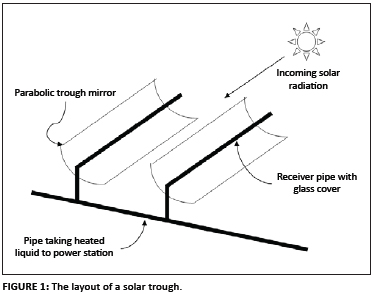
The cylindrical trough-shaped parabolic mirrors produce a focal line by concentrating the sun's radiation. The receiver unit runs along the focal line, absorbs the concentrated solar radiation and is heated, thereby heating the working fluid inside it.1,6 The working fluid is then circulated to a power station where the thermal energy is converted to electricity. Generally, the receiver unit must be designed in such a way that it loses as little heat as possible via radiation, convection and conduction to its surroundings.6
The receiver consists typically of a glass cover which encapsulates a metal receiver pipe such that a vacuum is formed in between (Figure 2). The vacuum minimises convective losses from the heated receiver pipe to the surroundings.6 Conduction losses are reduced by minimising the contact between the receiver pipe and the glass sleeve.7 Thermal radiation losses are reduced by the use of a selective coating applied to the receiver pipe.8, 9 All aspects of the receiver units are topics of ongoing research, such as the optical, thermal and chemical properties of all the materials concerned; the vacuum integrity; thermal expansion; and which working fluid should be used.6 In this study we focused on the possibility of a substitute for the selective coating, namely a hot mirror coating on the glass cover, which could both decrease radiation losses and raise the operating temperature of the working fluid.
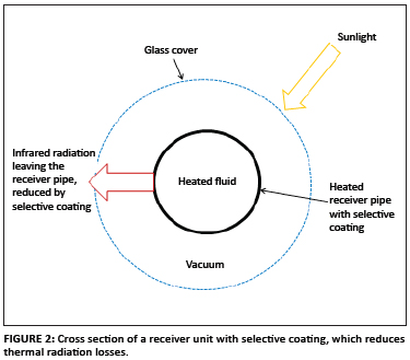
The selective coating is a dielectric material that absorbs well in the visible region of the spectrum (i.e. sunlight) but emits very poorly in the infrared region, which is the radiation that is lost from the receiver pipe.8,9,10 By using such a material, the dominant heat-loss mechanism at high temperatures (namely, radiation) can be diminished (Figure 2). A selective coating on the receiver pipe renders the system more efficient in terms of the fraction of solar energy absorbed by the working fluid, thereby heating it. Numerous work has been published on selective coatings on the receiver pipes and their properties.8,9 Some researchers have investigated ways to improve the optical properties such that the selective coating becomes more efficient at withholding heat; whilst others have sought to improve the thermal stability of the selective coating. Data from experimental facilities such as SEGS and computer simulations provide valuable insight on the effectiveness of selective coatings. The aim of research into selective coatings is to create a stable, efficient coating over a wide temperature range (0 ºC - 1000 ºC).
The main weakness of commercial selective coatings is that they deteriorate thermally at temperatures of about 680 K (~400 ºC),1,8,9,11,12 thereby restricting the maximum temperature to which the receiver pipe can be heated, and hence the Carnot or Rankine efficiency of the subsequent heat to electrical conversion.13 The temperature of the receiver pipe rises with its length, hence the receiver pipe length is restricted to a maximum length, after which thermal breakdown of the selective coating occurs.
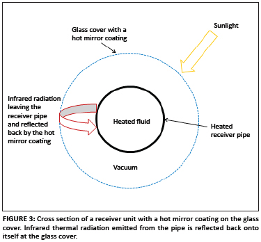
Therefore in this study, we investigated the theoretical performance of an alternative to the selective coating: the 'hot mirror'. A 'hot mirror' refers to a dielectric coating that is designed to reflect the infrared region of the spectrum and to transmit the visible region. The hot mirror reflects infrared radiation emitted from the receiver pipe back onto itself, thereby reducing the amount of thermal radiation leaving the receiver unit (Figure 3). The net effect is similar to that of the selective coating. The hot mirror coating also breaks down thermally at about 680 K.7 In our model, the hot mirror is applied to the inside of the glass cover, which is about 200 K cooler than the receiver pipe during operation. It is therefore possible to sustain higher temperatures in the receiver pipe using a hot mirror on the glass cover instead of a selective coating on the receiver pipe. This additional temperature increase is transferred to the working fluid, and subsequently to the steam power station, where it should improve thermal effciciency.8 In essence, therefore, we are addressing the problem of the temperature ceiling (~680 K) in existing systems, because the use of a hot mirror sidesteps the problem of thermal decomposition of the selective coating and thereby allows for a higher temperature of the working fluid.
The questions we posed in this study were: (1) how does a hot mirror system compare to a selective coating system in terms of efficiency of heat transfer into the working fluid and (2) can a hot mirror system be used in a temperature region of the receiver pipe where the selective coating system breaks down (>680 K). To the best of our knowledge, a hot mirror system has not been studied in this context. We could also find no reference to the possibility of a hybrid system, where different types of technologies are used at different temperature ranges, as in this study.
Heat transfer analysis of the receiver unit
We calculated the dominant radiative heat transfer mechanism between the receiver pipe and the glass cover, dividing the radiation into visible and infrared. We further included the heat transfer to the working fluid and convection losses from the glass cover to the surroundings. The resulting equations are functions of the absorption or emission coefficients of the glass cover and receiver pipe in the visible and infrared spectra. By adjusting these coefficients, we simulated selective coating and hot mirror systems.
Our model describes the radiative heat transfers between the glass cover, the receiver pipe and the surroundings, as well as the conductive heat transfer into the working fluid and convective losses to the surroundings. The relevant equations for these heat transfers are presented below.
The equation for radiative heat transfer (Q) is

where ε is the emissivity of the material, σ is the Stephan-Boltzmann constant and T1 and T2 are the temperatures in Kelvin of the surroundings and the material, respectively.
The equation for convective heat loss (Qconv) is

where hv = ac + bw.u and ac is the convection factor, bw is the wind factor, u is the wind speed (m/s),1,11 Ag is the area (m2) of the glass cover and Tg and T0 are the temperatures (K) of the glass cover and the surroundings, respectively.
[Eqn 1] and [Eqn 2], usually applicable to flat surfaces, are used as a simplification. If the glass cover and the receiver are closely separated compared to their radius, this will be a reasonable approximation. A more detailed model is needed to take into account a breakdown of this assumption.
The equation describing the heat transfer from the receiver pipe into the working fluid (QLC) is
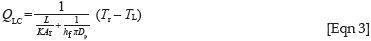
where K is the thermal conductivity of the material, Ar is the receiver area, Tr is the temperature of the receiver (K), TL is the temperature of the working fluid (K), L is the thickness of the receiver (m), hf is the heat transfer coefficient (W/m2K) between the wall and the working fluid and Dp is the pipe diameter (m).
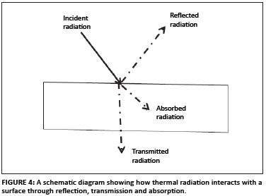
Heat transfer mechanism
Radiation interacts with a surface via the mechanisms of reflection, transmission and absorption (Figure 4),1,11,14 where 'r' and 't' are the reflection and transmission coefficients, respectively, and absorption (a) = 1-r-t. In each case, the superscript refers to whether the term of interest applies to visible (v) or infrared (IR) and the subscript refers to the physical location, being either on the glass cover (g) or the receiver pipe (r).
The physical mechanism we describe mathematically is this: the (visible) solar radiation from the parabolic mirrors is incident on the glass cover with power Qvisible denoted Qv. A fraction of this radiation is transmitted with transmission coefficient, tgv. Some is reflected with reflection coefficient rgv and the remainder (1 - tgv - rgv) is absorbed, which heats the glass cover and causes it to emit in the infrared region (Figure 5).14
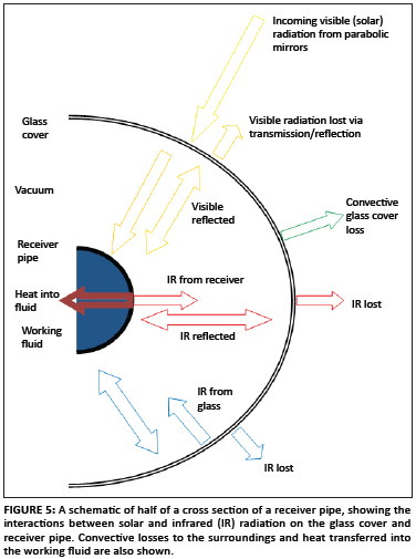
The transmitted visible light is incident on the receiver pipe. Again, this radiation is reflected, transmitted and absorbed. In this case, transmission on the receiver is negligible, because virtually no visible light passes through the metal of the receiver pipe. The reflected visible light from the receiver pipe interacts again with the glass cover via the three mechanisms. This infinite series of interactions can be summed.11 The visible light absorbed by the receiver pipe heats it and causes it to emit infrared radiation with power Q IRreceiver (denoted Q IRr ) and some emission coefficient, εr. This radiation strikes the inside glass cover where a fraction of it is reflected as Q IRReflected,glass (the fraction depends on the reflection coefficient of infrared on glass, rIRg ), some is transmitted as Q IRTransmitted,glass (with a fraction tIRg ) and the remainder is absorbed, further heating the glass cover.14 The heated glass cover radiates in the infrared region with power QIRg and an emission coefficient εg, both to the inside (where it is again partially absorbed by the receiver pipe) and to the outside of the glass cover (where it is lost to the surroundings). On the outside of the glass cover we must also account for the convective losses to the surroundings, Qconv. Further, a term describing the heat flow into the working fluid (QLC), depending on the temperature gradient between the inside of the receiver pipe and the fluid, is included.
Using the conservation of energy, we derived the following equations for the heat incident on and emitted by the glass cover and the receiver pipe14:
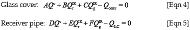
The variables A to F depend on the various reflection and transmission coefficients as follows:
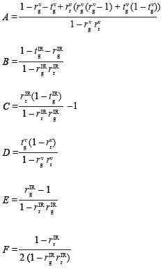
where the reflection or transmission coefficients are defined above.
A simple model of this type captures the dominant heat movement effects of the system. We did not specifically consider convection and conduction interactions inside the receiver unit, because they are subleading mechanisms of heat transfer at high temperatures and can also be assumed to remain similar in both systems.
A more realistic, but complex, model can be created if some or all of the following major approximations are addressed. The model is nevertheless suitable to answer the main questions posed in this study. The approximations used in this calculation were, firstly, the strict division of the radiation into visible (defined as 390 nm - 2000 nm) and infrared bands (mid-infrared to far-infrared, 2000 nm - 7000 nm). Coatings have different and complicated interactions within these regions, and average constants for both absorption and transmission were assumed. The averages were chosen to be close to the value near the dominant wavelength, found from Wien's law.1,2 Defining the visible part in this way further allowed us to ignore the infrared interaction from direct sunlight with the glass cover, which should be analysed in a more detailed model. These effects are likely to be similar for both the selective coating and the hot mirror coating.
Secondly, the calculation was performed on a two-dimensional cross section of the glass cover and receiver pipe. We thought it was justified to extend the model to three dimensions because the temperature along the receiver pipe varies slowly enough so that the radiation loss along the pipe from one cross-sectional element is similar to the radiation gained by its neighbour. The heating of the receiver unit was assumed to be uniform; we did not take into account a temperature gradient along the circumference of the glass cover or receiver pipe but assumed good heat conduction of the materials involved.
Further, we assumed the glass cover and the receiver to be close enough together so that the majority of the radiation leaving either one was intercepted by the other. This assumption is certainly the case for the radiation leaving the receiver pipe. It is clear that unless they are infinitesimally close to each other, some small fraction of the radiation leaving the glass cover will be lost by not striking the receiver pipe. However, this lost fraction will be partially absorbed by the glass cover again, remaining within the system, so we are somewhat justified in this approximation. We also did not include any heat transfer effects into the working fluid because of the type of flow it displays; laminar flow was assumed. We also did not include the abovementioned subleading heat transfer mechanisms, namely convection and conduction, inside the receiver.
We summed the incoming and outgoing contributions in the visible and infrared regions for both the glass cover and the receiver pipe using [Eqn 1]. We further substituted for the amount of heat being transferred to the liquid using [Eqn 3], and the heat lost from the glass cover to the surroundings by convection using [Eqn 2]. These calculations yielded the two coupled equations for the unknown temperatures of the glass cover (Tg) and the receiver pipe (Tr), shown below14:
where Ar and Ag are the unit areas of the receiver pipe and glass cover, respectively, which are active in heat transfer.
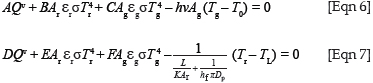
The equations were solved for Tg and Tr using a numerical program that we wrote. The variables A to F were interpreted as giving the amount of radiation (visible or infrared) absorbed by a given surface of interest. At an equilibrium temperature, the amount of heat absorbed by any surface is equal to the amount of heat loss. In [Eqn 4], the glass cover loses heat mainly via infrared radiation, making C negative. In [Eqn 5], E is expected to be negative for a similar reason. The last terms in [Eqn 6] and [Eqn 7] represent heat loss from the glass cover via convection to the surroundings ([Eqn 6]), and heat loss to the working fluid via conduction ([Eqn 7]). Both heat transfers depend on the local temperature difference linearly. These assumptions have been tested in numerous limits of coefficient and provided the expected results argued on purely physical grounds.
[Eqn 6] and [Eqn 7] can be used to obtain the equilibrium temperatures of both the receiver pipe and the glass cover at any point along the length of the receiver unit for any given working fluid temperature. From these temperatures, all relevant heat flows in the system can be calculated, notably the heat flow into the working fluid and the total heat loss to the surroundings. From these results, efficiency comparisons can be undertaken and questions regarding thermal decomposition answered.
Computer simulation
We have written a program that simulates the behaviour of a solar trough system.14 Solar radiation is incident on a section of the receiver unit, where it undergoes the aforementioned interactions leading to [Eqn 6] and [Eqn 7]. The program solves these equations simultaneously for the equilibrium temperature of the glass cover and receiver pipe. From these temperatures, all equilibrium heat flows can be calculated. The initial working fluid temperature is known and the final temperature as the working fluid exits the pipe section can be computed and used as the initial input for the following pipe section.
Quantities derived from the program include the equilibrium temperatures of the glass cover, the receiver pipe and the working fluid at incremental points along the length of the receiver pipe, as well as all heat flows related to the system. Efficiencies were also computed. For the simulations, we used an MS Visual Basic program coupled with an MS Excel worksheet.15 We further checked the results against an independent program, Math CAD.16
Because finite sections of length were considered, the temperatures obtained were averages over that section. It was found that, because the temperature variation was small along the pipe, the results were not very sensitive to the length of the section when sections shorter than 0.5 m were used. We therefore used a length of 0.25 m in the simulation. Errors introduced by the program were mainly as a result of this finite length approximation. Yet the errors were similar for both the selective coating and the hot mirror, so our comparison of the performance of a hot mirror to that of a selective coating was still taken to be valid for the aims of this study.
The variables used to simulate the selective coating and the hot mirror are given in Table 1.7,8,11,12,17 The transmission and reflection values for the selective coating were taken from commercially used units.6,17 Commercial firms, such as SCHOTT,7 use thin film technology to create custom made hot mirror coatings. The coating appropriate for our application should have good transmittance in the visible range up to a wavelength of about 3000 nm, and should reflect well in the infrared range, upwards from about 3000 nm. There were two reasons for choosing commercially used units. Firstly, a receiver pipe temperature of ~600 K will have a wavelength maximum of about 4500 nm, which must be reflected back by the hot mirror coating. Secondly, radiation coming from the sun at this wavelength (>3000 nm) will also be reflected by the glass cover, and therefore not reach the receiver pipe. The contribution of wavelengths higher than 3000 nm from the solar spectrum is small (<5%) and so are the losses of this type. As an example, for the present simulation we used values from the existing indium tin oxide coating.18
Transmission (tg) and reflection (rg) in the visible region for the glass cover were taken as 0.9 and 0.04, respectively, for both the selective coating and the hot mirror. Transmission of the receiver pipe (tr) was set to zero for both visible and infrared radiation. The selective coating was modelled by setting the reflection of the receiver pipe in the visible region to a low value (rr = 0.04; i.e. it absorbs well) and reflection in the infrared region to a high value (rr = 0.8; i.e. it absorbs poorly and emits poorly). The optical characteristics of the glass cover were within a conventional range.7 The hot mirror system was modelled by making the reflection coefficient in the infrared region high (rg = 0.7). The receiver pipe had thermal characteristics close to a darkened steel pipe without selective coating.7,11
Results and discussion
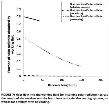
The temperatures of the glass cover and the receiver pipe for both the selective coating and the hot mirror systems as a function of the length of the solar trough system is shown in Figure 6. The efficiency of the heat transfer into the working fluid (compared to the total incident solar radiation) is shown in Figure 7 for the selective coating and hot mirror systems, as well as for a system with no coating.
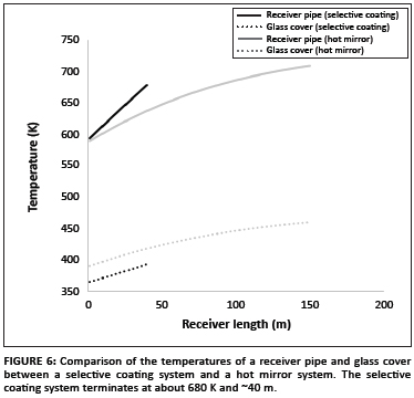
The simulation was started at a temperature close to where failure of the selective coating is expected (i.e. 600 K). Relative efficiencies of the selective coating and the hot mirror can thus be compared in this region. It can be seen in Figure 6 that, for the chosen parameters of the selective coating and the hot mirror, the selective coating performed better in the sense that the receiver pipe increased to a similar temperature as the hot mirror but over a shorter distance. This result implies a higher heat transfer for the selective coating into the working fluid compared to the hot mirror at the same length, because the temperature gradient between the pipe and the fluid is larger. This effect is also seen in Figure 7. Hence the selective coating should be used at the temperatures where it is stable (below 680 K). After this critical temperature, a substitution to the hot mirror system is advisable. The glass cover temperature is seen to be much lower than the receiver pipe temperature (about 200 K lower), and this allows the glass cover to be coated with a hot mirror, because the hot mirror coating can operate at these temperatures (~500 K). The hot mirror allows the working fluid to be heated to more elevated temperatures, making the overall system more efficient. It should be noted that our choice of values for the hot mirror coating properties was on the conservative side, and the hot mirror can perform better in terms of infrared reflection, elevating the stagnation temperature. This is a detailed engineering concern and will be addressed in a future communication.
Figure 7 indicates the efficiency of heat moving into the working fluid [(heat into working fluid, QLC)/(total incident solar radiation, Qv)]. It can be seen that both the selective coating and the hot mirror perform much better in terms of working fluid heat transfer than a system without either, making both suitable for increasing the efficiency of a solar trough plant.
Conclusions
We investigated the general performance of a hot mirror system compared to that of a selective coating system in terms of efficiency of the heat transferred into the working fluid of a solar trough system. We also investigated the possibility of using a hot mirror system to replace the currently used selective coating system at temperatures beyond which the selective coating system functions.
A set of heat transfer equations was derived to model the thermal behaviour of a solar trough receiver unit. Radiative heat transfer within the receiver unit was considered, as well as convective losses to the outside, and heat transfer into the working fluid. A code was written using the equations, and was the main source of our results.
Firstly, it was seen that, for our chosen parameters for the hot mirror and the selective coating, the hot mirror system performed slightly more poorly in terms of heat transfer into the working fluid, but much better than a system with no coating. An optimised hot mirror system may be a candidate to replace a selective coating system in a temperature range (above 500 K) for which the selective coating is not useful.
Secondly, it was seen that the glass cover temperature was sufficiently low for a hot mirror system to remain operational beyond temperatures currently available to a commercial selective coating system. This finding allows the construction of solar trough systems with longer receiver pipes of two types: a receiver pipe with a selective coating used in a low temperature region and a receiver pipe with a hot mirror system used in the region of high temperatures. This hybrid system will allow the working fluid to reach a higher temperature, and hence to perform better overall. For this purpose, it would be well worth further investigating the hot mirror system.
The weakness of the hot mirror system is that it performs slightly more poorly in terms of heat transfer into the working fluid, at least for our choice of parameters. The reflectivity of a hot mirror changes significantly with a change in wavelength, even in the infrared region. Generally, shorter infrared waves are better reflected, making the hot mirror system useful at higher temperatures. Further, it is necessary for a solar trough plant to switch between a selective coating and a hot mirror at some length of the receiver pipe, using both technologies. Also, depending on what type of hot mirror is used, the glass cover may nevertheless reach quite high temperatures. We have not addressed detailed questions such as cost effectiveness or a detailed design for a receiver unit with a hot mirror coating. The main purpose of this study was to highlight the possibility of an alternative to the conventional selective coating.
Acknowledgements
We wish to thank L. Nayager and P. Taylor for their help and useful comments.
Competing interests
We declare that we have no financial or personal relationships which may have inappropriately influenced us in writing this article.
Authors' contributions
M.C. Cyulinyana completed the study as part of her MSc in Physics at the University of the Witwatersrand. The calculations were performed by her and checked by P. Ferrer. M.C. Cyulinyana worked on the simulations and collated the results. The study was conceived and supervised by P. Ferrer, who formed the outline of how the project should proceed and wrote the code for the simulations.
References
1. Twidell J, Weir T. Renewable energy resources. New York: Taylor & Francis, 2006; p. 115-145. [ Links ]
2. Solar Cookers International. Solar cookers: How to make, use and enjoy. 10th ed. Sacramento: Solar Cookers International; 2004. Available from: http://solarcooking.org/plans/Plans.pdf [ Links ]
3. Mckay JC. Sustainable energy - without the hot air [book on the Internet]. c2009 [cited 2010 Jul xx]. Available from: www.withouthotair.com [ Links ]
4. Kaltschmitt M, Streicher W, Wiese A. Renewable energy technology - economics and environment. Berlin: Springer; 2007. [ Links ]
5. Sen Z. Solar energy fundamentals and modeling techniques. London: Springer Verlag; 2008. [ Links ]
6. Sargent & Lundy LLC Consulting Group. Assessment of parabolic trough and power tower solar technology cost and performance forecasts: Prepared for the US Department of Energy and National Renewable Energy Laboratory. Subcontractor Report, SL-5641 [document on the Internet]. c2003 [cited 2007 May]. Available from: http://blum.home.cern.ch/blum/Studie/Dok-A4/CSP-DoE-Assessment.pdf [ Links ]
7. SCHOTT DURAN®. Tubing, capillary and rod of borosilicate glass 3.3 [document on the Internet]. No date [cited 2010 Sep]. Available from: http://www.schott.com/tubing/english/download/schott-tubing_brochure_duran_english.pdf [ Links ]
8. Kennedy CE, Price H. Progress in development of high-temperature solar-selective coatings. NREL/CP-520-36997. Paper presented at: ISEC2005. Proceedings of the 2005 International Solar Energy Conference; 2005 Aug 06-12; Orlando, FL, USA. [ Links ]
9. Kennedy CE. Review of mid- to high-temperature solar selective absorber materials. Golden, CO: National Renewable Energy Laboratory; 2002. http://dx.doi.org/10.2172/15000706 [ Links ]
10. Sørensen B, Breeze P, Storvick T, et al. Renewable energy focus handbook. Oxford: Elsevier; 2009. [ Links ]
11. Kreith F, Kreider JK. Principles of solar engineering. Washington DC: Hemisphere Publishing; 1978. [ Links ]
12. You Y, Hu EJ. A medium-temperature solar thermal power system and its efficiency optimization. Appl Thermal Eng. 2002;22:357-364. http://dx.doi.org/10.1016/S1359-4311(01)00104-1 [ Links ]
13. Ferrer P. Enhanced efficiency of a parabolic solar trough system through use of a secondary radiation concentrator. S Afr J Sci. 2008;104:383-388. [ Links ]
14. Cyulinyana MC. Investigation into applicability of existing renewable energy technologies and possible efficiency increase. Case study: Rwanda. MSc thesis, Johannesburg, University of the Witwatersrand, 2011. [ Links ]
15. Microsoft Office Excel. 2007. Redmond, WA: Microsoft Corporation; 2007. [ Links ]
16. Mathcad Plus. Version 6.0 Professional edition. Cambridge, MA: Mathsoft Inc.; 1995. [ Links ]
17. Kumashiro Y. Electric refractory materials. New York: Marcel Dekker; 2000. http://dx.doi.org/10.1201/9780203908181
18. Xu Y, Gao J, Zheng X, Wang X, Wang T, Chen H. Deposited indium-tin-oxide (ITO) transparent conductive films by reactive low-voltage ion plating (RLVIP) technique. J Lumin. 2007;122-123:908-910. [ Links ]
 Correspondence to:
Phil Ferrer
Postal address:
PO Box Wits
Johannesburg 2050, South Africa
Email: Philippe.Ferrer@wits.ac.za
Received: 16 Nov. 2010
Accepted: 20 June 2011
Published: 02 Nov. 2011
© 2011. The Authors. Licensee: AOSIS OpenJournals. This work is licensed under the Creative Commons Attribution License.

