


Services on Demand
Article
 English (pdf)
 Article in xml format
 Article references
Indicators

Related links
-
 Cited by Google
 -
 Similars in Google
Share

 Permalink
South African Journal of Science
On-line version ISSN 1996-7489
Print version ISSN 0038-2353
S. Afr. j. sci. vol.105 n.7-8 Pretoria Jul./Aug. 2009
RESEARCH ARTICLES
Microstructure cantilever beam for current measurement
H.A.B. Mustafa; M.T.E. Khan*
Centre for Distributed Power & Electronic Systems, Faculty of Engineering, Cape Peninsula University of Technology, P.O. Box 1906, Bellville 7535, South Africa
ABSTRACT
Most microelectromechanical systems (MEMS) sensors are based on the microcantilever technology, which uses a broad range of design materials and structures. The benefit of MEMS technology is in developing devices with a lower cost, lower power consumption, higher performance and greater integration. A free-end cantilever beam with a magnetic material mass has been designed using MEMS software tools. The magnetic material was used to improve the sensitivity of the cantilever beam to an externally-applied magnetic field. The cantilever was designed to form a capacitance transducer, which consisted of variable capacitance where electrical and mechanical energies were exchanged. The aim of this paper was to analyse the system design of the microcantilever when subjected to a magnetic field produced by a current-carrying conductor. When the signal, a sinusoidal current with a constant frequency, was applied, the cantilever beam exhibited a vibration motion along the vertical axis when placed closer to the line current. This motion created corresponding capacitance changes and generated a voltage output proportional to the capacitive change in the signal-processing circuitry attached to the microcantilever. The equivalent mass-spring system theory was used to describe and analyse the effect of the natural frequency of the system vibrations and motion due to the applied magnetic field, in a single-degree of freedom. The main application of this microcantilever is in current measurements to develop a non-contact current sensor mote.
Key words: MEMS, microcantilever, capacitance transducer, mass-spring
Introduction
The microcantilever is a very useful shape in miniature devices and has been used successfully in many microelectromechanical systems (MEMS) sensor technologies, such as accelerometers, rotational motion sensors and, more recently, current sensors.1 The design of the cantilever shape is dependent on its application. For example, different microcantilever shapes have to be designed and used with corresponding variation in sensitivity for accelerometers and current sensors.2,3 In this application, a free-end cantilever beam was designed to sense the current flowing in a current-carrying conductor. A microelectro-mechanical system's performance and applicability depend directly on the synthesis topologies, configurations, electro-magnetic systems and mathematical models etc., that were used in its development. There is room for much improvement in MEMS design techniques.4
One of the techniques that were used to determine the stress and strain on a certain physical structure was the finite element method (FEM).5 The FEM separates the actual shape of the structures into finite geometrical elements, whereby each element represents a portion of the physical structure and all are joined by shared nodes. The collection of these elements and nodes is called a mesh.6
The natural frequency of the beam affects the behaviour of the device in response to an external signal. The large deflection of the beam depends on the dimensions of the beam, which also affect the natural frequency. Therefore, it is important to determine the frequency of the vibration mode due to its mechanical element as well as the equivalent electrical part, to obtain a measurement of one or more of the characteristics of the external signal. The mass-spring system was used to describe the behaviour of a cantilever-beam when a magnetic force was applied.7 Large signal deflection of the beam is an approach that may be used in the estimation of the maximum detectable signal.
Many laboratory techniques have been developed in recent years to manufacture microdevices; software has also been developed to simulate these devices to assist studies of physical structures, layouts and analysis of these miniature systems. CoventorWare software was designed to accurately reproduce MEMS design models and support both system-level and physical design approaches. The system-level approach used libraries of tools with a high-speed system simulator to create two-dimensional layer outputs, and the physical approach converted the two-dimensional models to three-dimensional models. The major components of this software are the Material Properties Database (MPD), Processor Editor, Architect, Designer, Meshing, Analyzer and Systems Integrator.
Structure and design
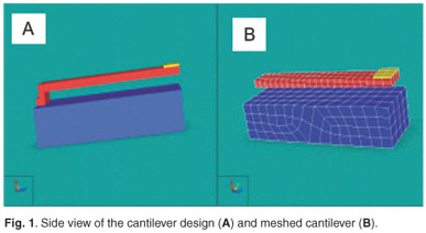
Silicon was the basic material used to build up the microcantilever using MEMS tools in CoventorWare 2006. The initial dimensions are shown in Table 1. The commercial and structural properties of the silicon are well known throughout the electronics industry and silicon also is the material of choice in MEMS development. The base (ground) and beam of the cantilever in this study also consisted of silicon. A mass, made of nickel, was added on top of the beam to improve the magnetic sensitivity. Nickel was selected as one of three ferromagnetic materials considered to improve the beam's sensitivity to a magnetic field. The beam was designed to be fixed at one end, allowing the other end to be free. This cantilever design is called a free-end cantilever beam. The area of the beam (the movable plate) is smaller than the area of the base (the fixed plate). Two layers of aluminium film were used to compose the capacitor. One aluminium layer was attached to the bottom of the beam and the other attached to the top of the base, making each layer an electrode. Fig. 1 shows the side view of the cantilever design and meshed model. The deflection of the beam in response to the magnetic field of an externally-applied current, is used to change the capacitance and thereby to measure the current as a function of the magnetic force.
Analysis of the beam vibration modes
The externally-applied current-carrying conductor was the source of the magnetic field to which the beam responded. The magnetic force existed along the vertical axis of the current-carrying conductor, according to Ampere's Law.8 To simplify the dynamic motion, the cantilever had to move in a single-degree of freedom in the direction of the beam along its vertical axis. If the beam vibrated due to the magnetic force, capacitance changes between the movable plate and the fixed plate occurred. In this case, it was important to ensure that the basic vibration mode of the structure caused the capacitance change, and not higher modes that could affect the reading due to smaller variations in capacitance value.9 A thorough modal and harmonic simulation was performed to analyse the vibration modes of the cantilever beam. The first six modes are shown in Fig. 2.
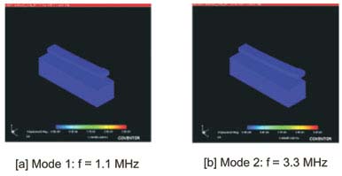
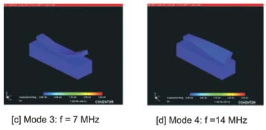
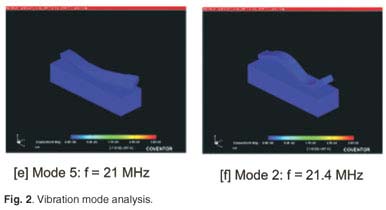
The first mode, shown in Fig. 2a, was suitable for the sensor requirement because the vibration mode was along the z-axis, normally called the fundamental frequency. The second mode, shown in Fig. 2b, allowed the beam motion along the y-axis. In this case the effective area did not change because the area of the beam was smaller than the area of the base, and the distance between them constant. If we refer ahead to Equation 18, the capacitance would remain constant and hence the mode would have no effect on the capacitance. The third mode, shown in Fig. 2c, indicates the transformation of the beam structure rotated symmetrically around the x-axis with a higher frequency than the first and second modes. In this case one has to consider a small-angle, tilted-capacitor design or eliminate the high frequency from the measurements. The effects of modes four, five and six can be ignored because the frequencies that were generated were much higher than in the first mode. Based on this analysis, the first mode was considered to be the most effective mode.
Modelling approach
Equation of motion of the cantilever beam
The Equation of motion of the cantilever beam subjected to a harmonic magnetic force is considered in this section. If the attached mass is a perfect conductor, then using the Method of Images which states that 'A line current above a perfect conductor induces an oppositely-directed surface current equivalent to an asymmetrically-located image line current' and Ampere's Law, one can derive the force per unit length induced by the current-carrying conductor on the mass-surface, shown in Equation 1:
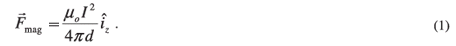
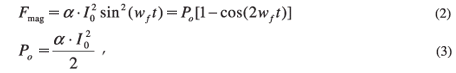
Here d is the distance between the perfect conductor and the centre of the line current, and µo = 4π × 10–7 is the permeability of free space. We considered the current induced to not be exactly equal to the current flowing in the conductor and multiplied by the factor (δ × I). Therefore the magnitude of the force generated by a current-carrying conductor
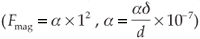
is very small. For a sinusoidal current (I = I0 sin wft), the force can be written as follows:
where Io is the amplitude of the current, wf = 2πf is the circular frequency of the current signal and f is the frequency of the current signal.
The dynamic characteristics of this system depend on the geometrical dimension and the material properties of the structure.3 There are considerations that need to be taken into account to simplify the dynamic system analysis. The material of the beam follows Hooke's Law—the flexure is a linear spring. The maximum flexure stress in the beam is less than the elastic limit of the beam. The thickness of the aluminium layer is very thin compared to the beam thickness so one can ignore the effect of the layer in the beam's elastic constant. The dielectric material between the beam and the base is considered to be a free space because the damping forces present a challenge in observing the oscillation behaviour of the system.10 The proposed application of the cantilever is to measure the beam deflection when it is placed closer to a current-carrying conductor. This will make the cantilever vibrate in relation to the applied magnetic force and generate a voltage output proportional to the capacitive change in the microcantilever. If the current carried by the conductor is a sinusoid wave, then the cantilever beam will be subjected to a harmonic force which usually is time-dependent along the vertical axis of the beam. The beam would exhibit harmonic motion that can be described using the well-known equivalent mass-spring system equation.
The harmonic motion of the mass-spring system in a single-degree of freedom usually is modelled with the second-order differential Equation given below:
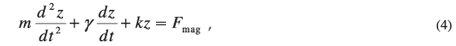
where m is the effective mass, γ is the damping coefficient of the dielectric material, k is the equivalent spring constant and F is the magnetic force. The effective mass is given by Equation 5, using the beam parameters as in Table 1.

where mo is the attached mass, Meq is the equivalent mass of the beam, and ρs and ρN are the density of silicon and nickel, respectively. Equation 6 shows k, the equivalent spring constant,
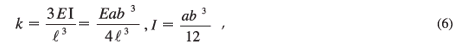
where E is the modulus of elasticity and I is the moment of inertia of the section.
Large deflection of the beam
The maximum applied force that does not bend the beam determines the large deflection of the beam, i.e. the total force that causes the maximum stress. When the beam stress is greater than the fracture strength, the beam will break. If the force is applied at the top of the attached mass, then the maximum stress (σmax) is at the top-end surface of the cantilever beam at the anchor, given by
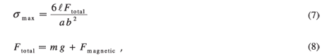
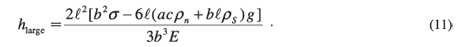
where g is the Earth acceleration constant.
The maximum magnetic force that can be applied to the cantilever beam is estimated by taking (σmax = σ), where σ is the fracture strength constant of the material of the beam. Using Equations 5, 6 and 7, we obtain the maximum magnetic force, called the maximum detectable signal, in Equation 9:

Referring to the tables of the dimensions of the cantilever and the material properties, we can estimate the maximum magnetic force by substituting the values of the parameters in Equation 9.
The large deflection is dependent on the maximum magnetic force applied to the cantilever beam and is given by Equation 10:

By substituting Equation 9 into Equation 10, we obtain Equation 11:
The height of the beam, which is the distance between the beam and the base, needs to be modelled in order to ensure that contact between them during the vibration motion is avoided. The initial gap capacitance is strongly dependent on this distance.
Natural frequency analysis
The natural frequency of the cantilever beam depends on the equivalent spring constant and the effective mass defined by Equation 12:

By substituting Equations 5 and 6 into Equation 12, we obtain Equation 13:
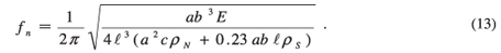
Using the dimensions of the cantilever and the material properties, we calculated the natural frequency (0.66 × 10⁶) Hz, and compared it to the fundamental mode frequency.
The effect of the natural frequency+
The complete solution of the Equation of motion is a combination of two parts. Part one is a complementary function and represents the vibration component while the other part is a particular solution representing the forced vibration component. The complete solution, in the case of no damping force (γ = 0), is given by Equation 14. The solution shows the displacement of the cantilever beam, which is time-dependent, and the amplitude of the motion, which is dependent on the input current. The solution also shows three interesting situations caused by altering the frequency ratio. Matlab was used to analyse these cases.
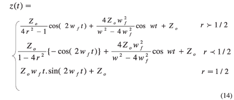
Where
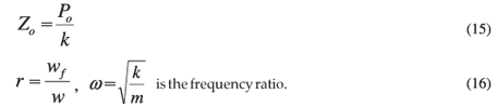
Figure 3 shows the case when the frequency ratio is closer to 0.5. The vibration takes place in a manner where the amplitude builds up and then dies out, repeating this behaviour continuously. This phenomenon is known as beating, and it is often observed in machine structures. When the frequency ratio is equal to 0.5, the amplitude is infinity and it is the resonant amplitude shown in Fig. 4.
In the case of r  0.5, (0
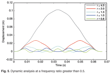
  w wf), the diagram in Fig. 5 shows the simulation of the Equation for different values of the frequency ratio. The frequency of the current signal is taken as a constant value of 50 Hz. Therefore the minimisation of the effect of the natural frequency in the beam's motion amplitude is possible by decreasing the value of the ratio as much as possible within the constraints.
In the case of r 0.5, (2wf w ∞), the diagram in Fig. 6 shows the simulation of the Equation for different values of the frequency ratio and constant force amplitude (2 ×10⁻¹⁰)N. The simulation shows that decreasing the ratio causes a decrease in the amplitude of the motion. The lower frequency, which is double the force frequency (2wf), is the motion frequency. The unlimited range of the natural frequency in this case gives an alternative in optimising the displacement gap of the cantilever beam.
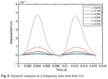
As noted above, this case is interesting for microcantilever structures, which normally have a high natural frequency. The advantage is that the effect of the natural frequency can be decreased to a very small amplitude of the system motion. Referring to Equation 6, we can prove that the maximum displacement is proportional to the amplitude of the force, as in the Equation below which was tested by simulation.

Linearisation analysis
A small-angle tilted-plate capacitor is assumed for the capacitance sensor between the movable beam and the fixed base. This kind of capacitor has two unparallel electrode plates with a small angle between them, as seen in Fig. 7. The total capacitance (C) of this capacitor is derived from the basic parallel plate capacitance in Equation 18, but takes into account a very small angle of tilt.

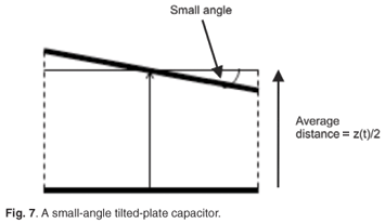
Here ε is the dielectric constant, S is the effective area, have is the average distance between the two plates. The area of the layer under the beam is the effective area, which is designed to be equivalent to the beam area but smaller than the area of the layer over the top base or ground. Referring to Fig. 3, we can write
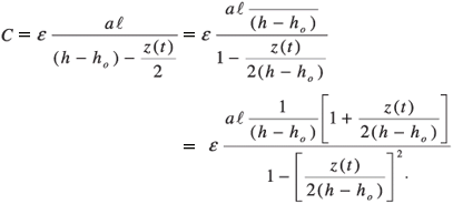
Then by using the approximation
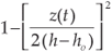 ≈ 1 when
 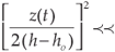 1 Equation 19 can be witten as a function of time.
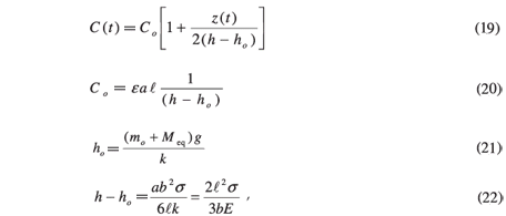
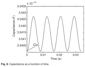
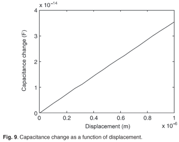
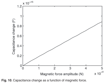
where Co is the initial capacitance at the equilibrium position for the free vibration due to the effective mass, and ho is the displacement due to the effective mass. Fig. 8 is a plot of the capacitance as a function of time; the initial capacitance is the minimum value of the capacitance, and it cannot be less than this value except when the applied force is more than the sum of the weight and Hooke's force—in the case where the beam moves backward from the base (ground). The capacitance change at the maximum displacement is given by Equation 23 and the ratio of the capacitance change by Equation 24. The diagrams in Figs 9 and 10 show the capacitance change proportional to the applied force, as well as the displacement.

By substituting Equation 17 into Equation 24, we obtain:

Thus

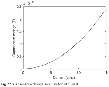
Equation 26 shows that the current value depends on the capacitance change. The current shows a parabolic relationship with the change in capacitance. This is shown in Figs 8–11.
Sensitivity analysis
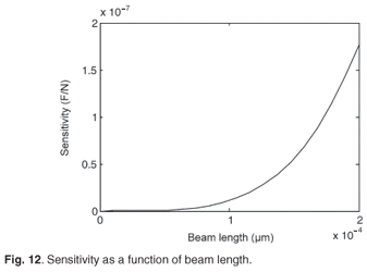
The sensitivity of the cantilever beam is defined by the capacitance per applied magnetic force. Therefore, the sensitivity formula was derived from Equation 25 and is given by Equation 27:

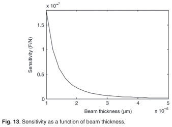
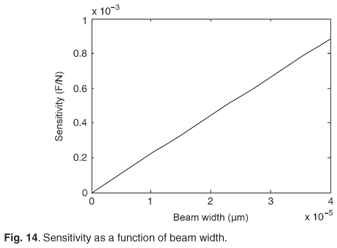
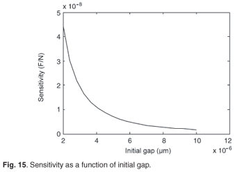
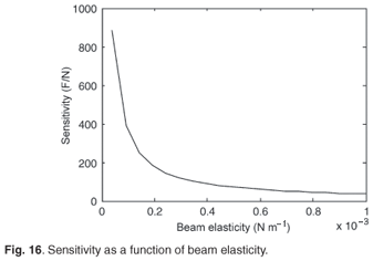
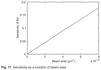
The effect of these parameters on the sensitivity is illustrated in Figs 12–17. The results show that the sensitivity increased with increases in beam length, width and area. The sensitivity decreased with increases in beam thickness, initial gap and beam elasticity.
Conclusions
Based on analysis of the vibration modes, the first mode is the most effective for developing a capacitance-based MEMS current sensor. The value of the frequency of the first mode determined from simulations corresponded well with the value calculated from the model, and the minor difference could be attributed to the different methods used in the software as opposed to the analytical model. The natural frequency of the microcantilever was very high compared to the frequency of the signal current at only 50 Hz. Therefore the effect of the natural frequency on the amplitude of the motion is very small. A linear relationship between the ratio of capacitance change and the amplitude of the motion (due to an applied magnetic field) was shown. A higher sensitivity can be obtained by designing optimal beam dimensions and this was simulated with consistent results. A viable design for developing a MEMS-based current sensor was achieved and will be manufactured henceforth.
1. Goedeke S.M., Allison S.W. and Datskos P.G. (2004). Non-contact current measurement with cobalt-coated micro cantilevers. Sens. Actuators A Phys. 112, 32–35. [ Links ]
2. Lee K.B. (2007). Closed-form solutions of parallel plate problem. Sens. Actuators A Phys. 133(2), 518–525. [ Links ]
3. Hu Y.C., Chang C.M. and Huang S.C. (2004). Some design considerations on the electrostatically actuated microstructures. Sens. Actuators A Phys. 112, 155–161. [ Links ]
4. Lyshevski S.E. (2002). MEMS and NEMS: Systems, Devices, and Structures. CRC Press, Boca Raton. [ Links ]
5. Mendels D.A., Lowe M., Cuenat A., Cain M.G., Vallejo E., Ellis D. and Mendels F. (2006). Dynamic properties of AFM cantilevers and the calibrations of their spring constant IOP. J. Micromech. Microeng. 16, 1720–1733. [ Links ]
6. CoventorWare (2006). Architecture Reference Manual. Coventor, Cary, NC. [ Links ]
7. Veijola T. (2001). Nonlinear circuit simulation of MEMS components: controlled current source approach. In Proceedings of the ECCTD 2001, Espoo, 28–31 August, vol. 3, pp. 377–380. [ Links ]
8. Marshall S.V. and Skitek G.G. (1990). Electromagnetic Concepts and Applications, 3rd edn. Prentice-Hall International, Englewood Cliffs, NJ. [ Links ]
9. Wang L. (2005). Mechanics of micro-capacitive accelerometer with U-shape cantilever. M.Sc. thesis, Cape Peninsula University of Technology, South Africa. [ Links ]
10. Harmany Z. (2003). Effects of vacuum pressure on the resonance characteristics of MEMS cantilever structures. In Annual Research Journal Vo1. I, Electrical Engineering Research Experience for Undergraduates, pp. 54–57. Department of Electrical Engineering, Pennsylvania State University, Pennsylvania. [ Links ]
Received 18 May. Accepted 29 July 2009.
* Author for correspondence E-mail: khant@cput.ac.za

