


Services on Demand
Article
 English (pdf)
 Article in xml format
 Article references
Indicators

Related links
-
 Cited by Google
 -
 Similars in Google
Share

 Permalink
South African Journal of Science
On-line version ISSN 1996-7489
Print version ISSN 0038-2353
S. Afr. j. sci. vol.103 n.11-12 Pretoria Nov./Dec. 2007
RESEARCH ARTICLES
Constructal design: geometric optimization of micro-channel heat sinks
T. Bello-Ochende†; L. Liebenberg; J.P. Meyer
Department of Mechanical and Aeronautical Engineering, University of Pretoria, Pretoria 0002, South Africa
ABSTRACT
This paper reports numerical optimization results for three-dimensional heat and fluid flow in a rectangular micro-channel heat sink using water as the cooling fluid. The conducting heat sink consists of silicon wafer. Numerical simulation was conducted on a unit cell which is a micro-channel heat sink with a fixed volume of 0.9 mm3 and a fixed axial length of 10 mm. Geometric optimization was carried out to determine the optimal aspect ratio of a unit cell of a heat sink that minimized the overall maximum temperature and thus maximized the overall global thermal conductance. The effect of total volume fraction of the silicon wafer on the optimal aspect ratio and minimized maximum temperature was also studied. Results show that as the pressure drop increases, the minimized peak temperature decreases, and suggests that there is an optimal allocation of solid volume fraction for a fixed pressure drop. The behaviour of the optimized volume is in agreement with the constructal design method, where the objective is to minimize the peak temperature, subject to the constraints of fixed total volume and solid (silicon wafer) material.
Introduction
The quest for improved designs for the cooling of heat-generating devices has long been the goal of modern heat transfer engineers and researchers. In an era of rapid advances in the development of new high performance microchips and electronic miniaturization, the trend is to install an ever-increasing number of heat-generating devices into a given space. The ability to remove heat from these devices has become an important challenge in the design of these components.1 In coming years, it is projected that the heat fluxes from these devices may exceed 100 W/cm2 and air cooling techniques are unlikely to be able to meet the cooling needs of these high heat flux electronic packages,2,3 which is why there is great interest in micro-channel cooling techniques. This development has also led to an increasing demand for highly efficient cooling technologies. To solve these problems, several novel techniques have been proposed and studied theoretically, numerically and experimentally. These techniques have been reviewed by Dirker et al.1 One of the new ideas is in the field of constructal design,4 where objectives and global constraint (fixed volume, area, etc.), lead to a geometric form which performs maximally under given constraints. Designing an optimal configuration for micro-channels, where space and size are constrained, has become an area of particular interest as optimization of flow system architecture is a widespread occurrence in engineering and nature.
We will atttempt to explore this technique in the optimal design of a given micro-channel. The flow configuration/geometry is the unknown, and is free to change. According to constructal theory, the optimization of geometry starts at the smallest (elemental) scale, which in this study is a unit cell of a micro-channel heat sink with a fixed volume and variable shape. Optimal geometry has been determined for natural convection,5,6 and for forced convection with specified pressure differences.7,8 Most of these works have been reviewed in ref. 4 and are not reviewed again here.
Significant research9–16 has also been conducted on the flow and heat transfer characteristics of micro-channel heat sinks because of the ability to remove heat from high heat flux areas. These studies relied on the finite volume method to study the flow and heat transfer characteristics. They captured results that were also obtained experimentally,9,17 and proved the viability of the finite volume method in the modelling of flow and heat transfer in heat sinks or flow in small length scales.
The purpose of this paper is to optimize numerically the flow configuration of a micro-channel heat sink, by using the finite volume method. The volume of the heat sink cooling channel and the volume of the conducting solid material are fixed. Also fixed is the axial longitudinal pressure drop. We seek to determine the optimal geometry for maximum global conductance (or minimized peak temperature).
Model and mathematical formulation
Figure 1 shows a schematic drawing of the physical model and the computational domain for a micro-channel heat sink. Heat is supplied to the highly conductive silicon substrate with known thermal conductivity from a heating area located at the bottom of the heat sink; it is then removed by a fluid flowing through a number of micro-channels as shown in Fig. 1. Using the advantage of symmetry, we select for analysis a unit cell consisting of a micro-channel and the surrounding solids, as is shown in Fig. 2. This selection is based on the models of Tuckerman and Pease, and of Kawano et al. First we reproduced the work of Tuckerman and Pease, then applied constructal techniques to the design according to the work of Kawano et al.15
The heat transfer in the unit cell is a conjugate problem that combines heat conduction in the solid and convective heat transfer in the liquid. The two heat transfer mechanisms are coupled through the continuity of temperature and flux at the interface between the fluid and the solid. The fluid with inlet temperature T0 is driven through the micro-channel by a fixed pressure difference ΔP = P(z = 0) – P(z = L), which is maintained between the channel inlet and outlet. The objective of the following analysis is to determine the heat transfer characteristics for a given micro-channel and the best possible configuration (L, t1/t2, t2/t3, H/G) which corresponds to the maximal global thermal conductance or global minimal thermal resistance.
The following assumptions were made to model the heat transfer and fluid flow in a unit cell under the conjugate model: the hydraulic diameter of the micro-channel under analysis is of the order of 100 µm; for water, the continuum regime applies hence the Navier-Stokes equation can still be used to describe the transport processes; steady-state conditions for flow and heat transfer; incompressible flow; the properties of the solid and fluid are constant; and the heat transfer due to radiation and natural convection are negligible. Based on these assumptions, the continuity, momentum and energy equations for the cooling fluid are
where ∇2 = ∂/∂x2 + ∂/∂y2 + ∂/∂z2, and the origin of the Cartesian frame (x, y, z) is located in the bottom left corner of the computational domain.
For the volume occupied by solid, the momentum equation is simply

and the energy equation is

The whole unit volume (cell) is treated as a unitary (continuous) domain. The geometric boundary conditions for the computational domains are indicated in Fig. 2. The flow boundary conditions are that no-slip occurs on the walls inside the channel. At the entrance of the channel, the pressure boundary conditions become

where Be is the dimensionless pressure number based on the unit volume.16,17 P = 1 atm at the channel outlet, and T = 20oC at the channel inlet. The thermal boundary condition consists of an assumed uniform heat flux that is imposed at the bottom of the heat sink
The remaining outside walls and the plane of symmetry of the heat sink were modelled as being adiabatic. The continuity of the temperature and flux at the interface of the solid and fluid surfaces requires
where n is the direction normal to the walls.
The shape of the heat sink and cooling channels are allowed to vary, by changing G, H, t1, t2 and t3. We are interested in the geometric arrangement that maximizes the overall global thermal conductance of the geometry, which in dimensionless form is defined as
Here q" is the heat flux from the base of the micro-channel heat sink, k is the thermal conductivity of the fluid, and L is the length of the computational domain of the unit volume. The global conductance C is a dimensionless way of expressing the ratio of the total heat transfer rate divided by the largest excess temperature (Tmax– T0) reached at any point in the heat sink. The reciprocal of C is defined as the dimensionless global thermal resistance.
Numerical method and code validation
The finite volume method was used to solve the continuity, momentum and energy equations. A detailed explanation is given in Patankar.19 In the finite volume method the domain is divided into a number of control volumes such that there is one control volume surrounding each grid point. The grid point is located in the centre of the control volume. The governing equation is integrated over each control volume to derive algebraic equations containing a point value of the dependent variable at the grid point. The discretized equations express the conservation principle for a finite volume.
The second-order upwind scheme was used to model the combined convection-diffusion effect in the transport equations. The resulting algebraic equations were solved using a line-by-line tri-diagonal matrix inversion algorithm. The SIMPLE algorithm18 was then applied to solve the coupled systems of equations. The solutions were considered converged with the criterion |(γi+1 – γi+1)/γi+1|<10–3, where γ represents u, v, and w, and i is the iteration number. An additional convergence criterion was that the residual of the energy equation was less than 10–9. A grid independence study was carried out for the dimensions given in Table 1 to determine their maximum thermal resistance. Tests show that for a control volume a mesh size of 20 in the x-direction, 40 in the y-direction and 150 in the z-direction ensures a grid-independent solution in which the maximum thermal resistance changes less than 2.5% when the mesh is sequentially doubled.
The numerical code was verified in several ways. The first method was to reproduce the work of Tuckerman and Pease9 and Toh et al.14 (see Table 1). The computational model in Fig 2 was amended by removing the solid component on top of the heat sink and replacing it with a plastic cover and making t3 = 0. The results obtained using the finite volume method were then compared with experimentally measured thermal resistance from different flow rates. The results of this work were then compared with experimental results supplied by Tuckerman and Pease9 using the local thermal resistance,

In Equation (12) R(x) is the thermal resistance at some distance x from the entrance. Tables 1 show the values of the dimensions used to validate the present numerical model.
Table 2 reports the maximum thermal resistance for three cases tabulated in Table 1. These thermal resistances were reported at z = 9 mm. Table 2 shows the comparison between the thermal resistance measured experimentally by Tuckerman and Pease,9 numerically by Toh et al.,10 and those calculated [using Equation (12)] in this study. The agreement with the experimental work is within 28% for case 1, 11% for cases 2 and 3, and within 2% for the numerical results.
In the second validation of the numerical results, the heating component in Fig. 1 was placed on top of the micro-channel heat sink, as in the work of Qu and Mudawar.11 The comparison was made for different Reynolds numbers in the range of 90 < Re < 400, where the Reynolds number is defined as

and the hydraulic diameter is
where Ac is channel cross-sectional area and S is the perimeter of the micro-channel. Figure 3 reports the thermal resistance for inlet and outlet for the cases tabulated in Table 1b. It can be seen that the present numerical analyses also capture the work of Qu and Mudawar,11 and predicts well the inlet and outlet thermal resistances. The maximum differences are 1.8% for the inlet and 1.5% for the outlet resistances.
Once the model adopted in this work was validated, numerical optimization was performed to determine the optimal geometry of the micro-channel using the constraints outlined in the next section. The above code verification and grid-independent test provide confidence in the numerical code and approach used in this work. A detailed optimization procedure for the heat sink is presented in the following section.
Optimization constraints and parameters
The theory of constructal design is applied to an arbitrary unit of micro-channel heat sink with a fixed given volume (length and cross-sectional area), and substrate material. The only parameter that is allowed to vary is the cross-sectional shape of the heat sink, and the ratio of the internal thickness of the vertical and horizontal substrate.
The elemental volume constraint for a given computational cell is

and the volume of the solid substrate is

For a fixed length we have

The volume of the micro-channel is

Equation (16) can also be expressed in terms of the solid volume fraction, ø = Vs/V = As/A. Equations (16)–(18) can be solved simultaneously for t1, t2 and t3 such that for any changes in the assumed thickness and geometric parameters, the aspect ratio (t1/t2, t2/t3, H/G and ø), the total volume, and volume of solid substrate remain fixed. Because the volume remains fixed, the cross-sectional shapes of the heat sink changes in such a way that the solid substrate conducts the heat from the base such that the thermal resistance is minimized. The total number of micro-channels in the heat sink is obtained by

for a fixed total width, W.
Results and discussion
A series of numerical optimizations and calculations has been conducted and the results are presented to show the effects of pressure drop, solid materials content, and effect of the external aspect ratio for a fixed set of internal aspect ratios (the ratio of base solid thickness to vertical thickness) on the optimal micro-channel geometry. Some important fluid flow and heat transfer parameters that are employed in this study are summarized in Table 1b. The thermo-physical properties of water used in this study are based on water at 20°C. The volume of the micro-channel is fixed and it is based on the data given by Qu and Mudawar.11 The applied heat flux at the bottom of the micro-channel was set at 100 W/cm2. We seek to determine the optimum geometry that minimizes the maximum temperature, Tmax, or the overall global conductance.
Optimal micro-channel heat sink
The heat sink has five degrees of freedom, L, H/G, t1/t2, t2/t3 and ø. For this study three degrees of freedom were fixed: L, t1/t2 and t2/t3, while the other two were allowed to vary with the assumed pressure drop. In the first stage of the optimization, we fixed the internal structure of the micro-channel by setting (t1/t2 = 0.08, t2/t3 = 1 and ø = 0.8). The total volume of the unit micro-channel was set to be V = 0.9 mm3, the axial length of the micro-channel was fixed at 10 mm, and the unit cross-sectional area was 0.09 mm2. The heat sink is expected to occupy a total base surface area of 10 mm × 10 mm. The pressure drop across a unit cell was set at 50 kPa for the first optimization. Figure 4 shows how the external shape H/G varies with Tmax (in all figures a marker is used for the result of the numerical study and a trend line is used to connect the markers). It shows that there exists an optimal micro-channel cross section that minimizes the maximum temperature at any point in the micro-channel arrangement. This procedure was repeated for different ranges of ø as shown in Fig. 5. This Figure suggests that there is an optimal allocation of solid fraction that minimizes the maximum temperatures.
Figure 6 summarizes the effects of pressure drop on the optimal external aspect ratio, in the range 10 kPa < ΔP < 75 kPa. For a fixed solid fraction, the optimal external aspect ratio exhibits two types of behaviour as shown in Fig. 6. At low pressure drop, the optimized  ratio increases with a rise in the pressure drop, while for DP > 50 kPa, increased slightly with increase in the pressure drop and almost invariant for ø = 0.8. Similarly, the optimized external aspect ratio decreases with an increase in the solid volume fraction for the range of geometric parameters investigated in this study. As the aspect ratio increases, the channel becomes more slender in the vertical direction and the value of the hydraulic diameter changes. The optimal hydraulic diameter decreases with increase in the aspect ratio and with a rise in the pressure drop. The minimum optimal hydraulic diameter Dh,opt = 102 µm is obtained for a pressure drop of ΔP > 50kPa and ø = 0.8, whereas the maximum Dh,opt value of 154 µm corresponds to a pressure drop ΔP = 10 kPa and ø = 0.3. In this work, the optimal hydraulic diameter lies in the continuum region and gives us confidence in our continuum assumption.
Figure 7 describes the behaviour of the minimized maximum temperature difference, (ΔT)min, with respect to the applied pressure drop. (ΔT)min decreases monotonically with increase in pressure drop. There is an optimal volume of the solid fraction and lies in the vicinity of ø = 0.5 and 0.4. For the range of assumed parameters represented in in Fig. 7, the line represented by ø = 0.5 and 0.4 is located below the lines corresponding to ø = 0.3 and ø = 0.8.

Figure 8 shows another way of reporting the results obtained in Fig. 7. The results are reported based on the dimensionless global conductance [Equation (11)] and dimensionless pressure drop number, Be, from Equation (8). The maximized global thermal conductance increases with an increase in Be. Figure 8 suggests an optimal solid fraction exists in the vicinity of ø = 0.5 and 0.4. This should be investigated further in future research. For ø = 0.5, the maximized global thermal conductance can be correlated within 0.05% with the power law

These results are in agreement with previous work on the constructal method,4 according to which maximum heat transfer density means optimal packing such that flow regions that do not contribute to global performance are eliminated.
For practical design purposes, Table 3 reports the geometry and the numbers of micro-channels in a heat sink arrangement for a given optimial geometry. The total base area for the silicon wafer is fixed at 10 mm × 10 mm. Results show that, as the pressure drop increases, the number of channels also increases for a given solid volume fraction. These trends break down for high solid volume fraction (ø = 0.8) and pressure drop (ΔP > 50 kPa). These values can be used in future experimental set-ups to validate the numerical results.
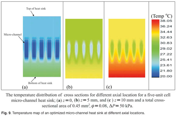
Figure 9 shows the temperature distribution of an optimized micro-channel heat sink with a unit volume of 9 mm3 (ΔP = 50 kPa, = 8, ø = 0.8, t1/t2 = 0.08 and t2/t3 = 1). The figure illustrates the temperature distribution at the inlet plane through to the outlet of the micro-channel heat sink; note that the deep blue colour shown at the inlet of the micro-channels gradually changes to light blue for the axial location of z = 5 mm and to green at the outlet (z = 10 mm), as heat is conducted away from the bottom of the unit. This temperature distribution varies almost linearly from the inlet to the outlet of the micro-channels and is distributed optimally along the given volume, so that the maximum temperature at any given point in the heat sink geometry is minimized. The temperature is a maximum at the exit plane for any given geometry,
Conclusion
This paper addresses the fundamental problem of numerically optimizing a three-dimensional rectangular micro-channel heat sink by solving the three-dimensional conjugate heat transfer model, in which the micro-channel's hydraulic diameter is in the order of 100 µm, which is in the continuum region. The heat sink uses water as the cooling fluid, and consists of silicon wafer. The total volume of the heat sink is fixed, as is the axial length. In the first part of this paper, the numerical code is validated against known numerical and experimental results for micro-channels and was found to be in agreement with them. Numerical optimization results show that the optimal aspect ratio of a unit cell is a function of the imposed pressure drop and the solid volume fraction. The numerical results also indicate that there is an optimal solid volume fraction.
The main conclusion is that constructal optimization procedures need to be implemented to optimize the thermal and flow field design of the micro-channel heat sink, which will lead to the best external shape (aspect ratio) that minimizes (maximized global thermal conductance) the temperature difference between the cooling fluid and the maximum temperature at any point in the heat sink geometry.
We recommend that for future work both the external and internal aspect ratios (all the degrees of freedom) should be optimized simultaneously. Also, that the effects of thermal stresses on the optimized geometry at such a small length scale should be investigated. We expect that the conceptual design of micro-channel heat sinks using the constructal method will lead to the improved design of heat sinks, with superior performance and enhanced global thermal conductance.
Nomenclature
| A | channel cross-sectional area, m2 |
| Be | Bejan number based on a unit volume |
| B | channel width, m |
| C | dimensionless global conductance |
| Cp | specific heat at constant pressure, J/kg.K |
| D | diameter, m |
| G | computational width (B + t1), m |
| H | height, m |
| k | thermal conductivity, W/mK |
| L | axial length, m |
| n | normal |
| num | number of micro-channels |
| P | pressure, Pa |
|
| flow rate, m3/s |
| q" | heat flux, W/m2 |
| R | thermal resistance, K.m2/W |
| Re | Reynolds number |
| S | perimeter of the micro-channel, m |
| T | temperature, K |
| T0 | inlet temperature, K |
| t1 | half thickness of the vertical solid, m |
| t2 | thickness of the base of the channel, m |
| t3 | top thickness of the micro-channel heat sink, m |
| u, v, w | velocity components in the x, y and z directions, m/s |
|
| velocity vector, m/s |
| V | volume, m3 |
| W | width of the heat sink, m |
| x, y, z | Cartesian coordinates, m |
| Greek symbols | |
| α | thermal diffusivity, m2/s |
| Δ | difference |
| µ | viscosity, kg/ms |
| ν | kinematic viscosity, m2/s |
| ρ | density, kg/m3 |
| ø | volume fraction of solid material |
| γ | dependent variable |
| Subscripts | |
| c | channel |
| f | fluid |
| max | maximum |
| min | minimum |
| opt | optimum |
| out | outlet |
| s | solid |
| h | hydraulic diameter |
| Ω | interface between the solid and fluid |


T.B-O. acknowledges support for post-doctoral research from the University of Pretoria and the National Research Foundation.
1. Dirker J., van Wyk D. and Meyer J.P. (2006). Cooling of power electronics by embedded solids. ASME Journal of Electronic Packaging 128(4), 388–397. [ Links ]
2. Webb R. (2005.). Next generation devices for electronic cooling with heat rejection to the air. J. Heat Transfer 127, 2–9. [ Links ]
3. Hetsroni G, Mosyak A., Pogrebnyak E. and Yarin L.P. (2005). Heat transfer in micro-channels: Comparison of experiments with theory and numerical results. Int. J. Heat Mass Transfer 48, 5580–5601. [ Links ]
4. Bejan A. (2000). Shape and Structure, from Engineering to Nature. Cambridge University Press, Cambridge. [ Links ]
5. Bar-Cohen A. and Rohsenow W.M. (1984). Thermally optimum spacing of vertical, natural convection cooled, parallel plates. J. Heat Transfer 106, 116–123. [ Links ]
6. Bejan A. (2004). Convection Heat Transfer, 3rd edn. Wiley, New York. [ Links ]
7. Bello-Ochende T. and Bejan A. (2003). Fitting the duct to the "body" of the convective flow. Int. J. Heat Mass Transfer 46, 1693–1701. [ Links ]
8. Bejan A. and Sciubba E. (1992). The optimal spacing for parallel plates cooled by forced convection. Int. J. Heat Mass Transfer 35, 3259–3264. [ Links ]
9. Tuckerman D.B. and Pease R.F.W. (1981). High-performance heat sinking for VLSI. IEEE Electron. Dev. Lett. EDL-2, 126–129. [ Links ]
10. Toh K.C., Chen X.Y. and Chai J.C. (2002). Numerical computation of fluid flow and heat transfer in micro-channels. Int. J. Heat Mass Transfer 45, 5133–5141. [ Links ]
11. Qu W. and Mudawar I. (2002). Analysis of three-dimensional heat transfer in micro-channel heat sinks. Int. J. Heat Mass Transfer 45, 3973–3985 [ Links ]
12. Knight R.W., Hall D.J., Goodling J.S. and Jaeger C.J. (1992). Heat sink optimization with application to micro-channels. IEEE Trans. Components, Hybrids, and Manufacturing Technology 15(5), 832–842. [ Links ]
13. Fedorov A.G. and Viskanta R. (2000). Three-dimensional conjugate heat transfer in the micro-channel heat sink for electronic packaging. Int. J. Heat Mass Transfer 43, 399–415. [ Links ]
14. Li J., Peterson G.P. and Cheng P. (2004). Three-dimensional analysis of heat transfer in a micro-heat sink with single phase flow. Int. J. Heat Mass Transfer 47, 4215–4231. [ Links ]
15. Kawano K., Minikami K., Iwasaki H. and Ishizuka M. (1998). Micro channel heat exchanger for cooling electrical equipment, Application of Heat Transfer in Equipment, Systems and Education. ASME HTD–361-3/PID-3, 173– 180.MM [ Links ]
16. Bhattacharjee S. and Grosshandler W.L. (1988). The formation of wall jet near a high temperature wall under microgravity environment. ASME HTD 96, 711–716. [ Links ]
17. Petrescu S. (1994). Comments on the optimal spacing of parallel plates cooled by forced convection. Int. J. Heat Mass Transfer 37, 1283. [ Links ]
18. Dirker J. and Meyer J.P. (2007). Cooling layers in rectangular heat-generating electronic regions for two boundary condition types: a comparison with a traditional approach. S. Afr. J. Sci. 103, 474–482. [ Links ]
19. Patankar S.V. (1980). Numerical Heat Transfer and Fluid Flow. Hemisphere, Washington, D.C. [ Links ]
Received 12 May 2006. Accepted 22 October 2007.
† Author for correspondence. E-mail: tbochende@tuks.co.za

