


Services on Demand
Article
 English (pdf)
 Article in xml format
 Article references
Indicators

Related links
-
 Cited by Google
 -
 Similars in Google
Share

 Permalink
South African Dental Journal
On-line version ISSN 0375-1562
Print version ISSN 0011-8516
S. Afr. dent. j. vol.79 n.1 Johannesburg Feb. 2024
http://dx.doi.org/10.17159/sadj.v79i01.18041
LITERATURE REVIEW
A simplified and evidence-informed approach to removable partial dentures. Part 4. Seven simple steps to design
CP Owen
Professor Emeritus, Faculty of Health Sciences, University of the Witwatersrand, Johannesburg, South Africa. ORCID: 0000-0002-9565-801
SUMMARY
For many decades the literature has regularly reported that there is a discrepancy between what is taught in dental school and what is practised, especially in the field of removable partial dentures. Not only that, but for more than 60 years reports from around the world have shown that, usually, the majority of clinicians abdicate their responsibility to design a removable partial denture (RPD) and instead leave this to the dental technician, who has no knowledge of the clinical condition of the patient and works only from a cast. Most patients around the world who require RPDs to improve aesthetics and chewing can only afford a removable prosthesis simply because the majority are poor. But RPDs can improve these aspects and contribute to an improved quality of life.
The purpose of this series of articles is to derive the basic, evidence-informed principles of partial denture design and to suggest a simplified explanation and application of those principles in the hope that clinicians will increasingly take responsibility for the design of partial dentures. Part 1 summarised studies revealing what can only be described as the malpractice of abdication of responsibility for design by clinicians, and then explained the evidence-informed basic principles of design; Part 2 looked at the biomechanical basis of those principles in terms of support; Part 3 did the same for the biomechanical basis of retention; this part will provide a simple seven-step approach to design, applied to an example of an acrylic resin-based and a metal framework-based denture for the same partially edentulous arch; and Part 5 will provide examples of designs for RPDs that have been successfully worn by patients, for each of the Kennedy Classifications of partially dentate arches. Much of this is referenced from an electronic book on the Fundamental of removable partial dentures.1
Keywords: Removable partial denture, design, support, retention, acrylic-based, framework-based
INTRODUCTION TO PART 4
This part will introduce a simple step-by-step procedure to design removable partial dentures using either acrylic resin as a base, or a framework. The illustrations will use a cast metal framework, but it could be cast, milled or sintered, and other material (such as polyetherketoneketone for example) could also be used. The principles remain the same, but the guidelines for clasp placement2 at the time of writing only exist for wrought and cast chrome-cobalt materials.
It should go without saying, but just as a reminder, before deciding on the design, it is necessary to have the following:
• study (diagnostic) casts of both arches, either articulated or model trimmed for hand articulation, with the aid of a bite registration if necessary
• patient records (history, examination, radiographs etc)
• dental surveyor
• l arge diagram of the remaining dentition.
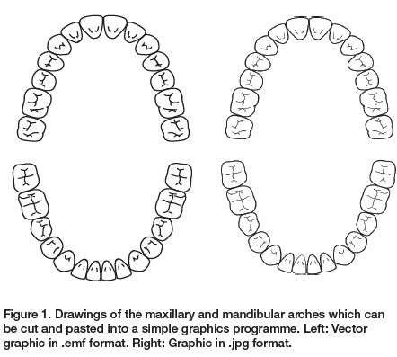
The latter is not absolutely necessary, but it is useful to draw the design as it progresses, and it might be useful to have a drawing of a full arch first, such as in Figure 1 which can be copied and pasted into a simple graphics programme such as Paint, where it is simple matter of erasing the lines representing the missing teeth.
The steps to a simple design are summarised in the box and will be dealt with sequentially.
The seven steps to making a design
1. Identify the need for replacement teeth and the materials to be used
2. Determine the path of insertion and survey the cast
3. Provide support
4. Provide retention
5. Connect the separate components
6. Ensure that there is horizontal and rotational stability
7. Record the prescription preferably as a drawing
Step 1. Identify the need and the materials to be used
Not all missing teeth need to be replaced, though this has been an adage used in promotional material put out by dental associations to assist practitioners in persuading patients that it is, in fact, necessary to replace every missing tooth. The main reason for replacing teeth as requested by patients is for aesthetics, but if there is evidence that the health of the remaining dentition depends on replacing teeth, then this is justified. Generally, if the patient has Ave or more posterior occluding pairs of teeth, chewing ability will not be impaired, but patients are not always willing to accept posterior spaces despite this evidence. Again, in keeping with the premise of these papers, the adage is to keep it simple, and only replace teeth when there is an evidence-informed decision to do so.
Having established the need, then decide on the materials to be used. This will almost always be a financial decision as to whether a framework will be used or an acrylic resin base. The principles in the design will remain the same: the difference is the gingival coverage required. A framework-based denture may never have to cover a gingival margin; an acrylic-based denture will have to cover gingival margins to provide support and strength and reciprocation.
Step 2. Determine the path of insertion and survey the cast
This will almost always be perpendicular to the occlusal plane, and must be done on a surveyor, because a slight tilt of the model might reveal a usable undercut. However, the tilt should not be excessive because the path of insertion so created may make manipulating the denture by the patient too difficult. Once the path of insertion is determined then the model must be surveyed in the normal manner, including the marking of re-locating marks on the cast. This will assist in comparing the surveying done on the diagnostic cast with that of the final cast, to ensure the same placement. This, of course, implies that you have a surveyor in the first place. If not, it is highly recommended to purchase one (it will last a lifetime) or do this designing together with your dental technician.
Step 3. Provide support
As has been shown in previous parts of this series, tooth support is an essential feature of every removable partial denture. Guidelines for preparing rest seats were given in Part 2 of this series,2 but in the design phase the position of the rests must now be determined. Point 8 of the guidelines stated that at least three rests are required, as widely spaced as possible.
This provides stability in support: for example, three legs to a stool is the least number possible - you would fall off a two-legged one. Point 9 stated that rests must be adjacent to any edentulous space being replaced. In a bounded saddle, that means on either side of the saddle. In a distal extension, that means on the abutment.
There has been, and still is, controversy as to the placement of rests on the abutment teeth for distal extension bases. Part 3 of this series dealt with the clasp systems that have been proposed for distal extension bases and much of that mythology still persists, often in the form, not of the RPI system, but of the placement of a mesial, rather than a distal, rest.3 This is still based on the clinically unproven idea that the abutment tooth is subjected to a torquing force.
There is very little evidence that a mesial rest makes any difference, and it often overcomplicates the design. In a somewhat inconclusive in vivo study of just four patients with mandibular distal extension bases with different occlusal rests on the distal abutments, no definitive conclusion could be drawn on the pressure distribution beneath the distal extension bases, whether the rests were both mesial and distal, mesial only, or distal only.4 So, in keeping with the theme of simplicity, a simple distal rest with a circumferential clasp (often wrought wire because of the length of the clasp arm as it is usually on a premolar or canine) has no evidence to contraindicate it.
As an example, a simple maxillary Class III, Modification 2 design will be used to illustrate the steps. Further designs, and how all these principles apply, will be shown as examples for all the other Kennedy classes and will be given in Part 5 of this series. So, on a suitable diagram draw in the possible sites for the rests, having identified which teeth will be replaced (Figure 2).
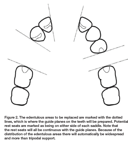
At this stage all potential rests are drawn in, but in many cases not all will necessarily be used. This may be because some teeth may not be suitable to sustain additional occlusal loads, some may be assisted by the distribution of loads and some, such as anterior teeth, may not have sufficient enamel and would require a restoration which could be avoided if other teeth can be enlisted for support. This, in fact, is illustrated in this case. Consider tooth 12: if the palatal surface is thin, because the 13 is going to receive a rest, only one tooth away from the anterior saddle, it will not be necessary to rest the 12.
Step 4. Provide retention
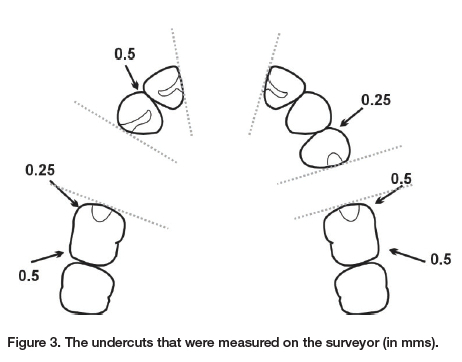
The first stage in this step is to write down the size of the undercuts that you have already measured after having surveyed the casts after having determined the path of insertion. With experience, you will already have an idea of which teeth will be clasped, but if you are fairly new to this, then measure everything (Figure 3).
The guidelines for clasp placement given in Part 3 (Point 5) stated that generally only one clasp per side of the arch is sufficient unless there is a long span edentulous space of three or more teeth to be replaced. This is a good rule of thumb and certainly works clinically, but in some countries dental technicians are paid per component, so they are keen to add as many as possible. Another reason why clinicians should be designing partial dentures.
In the case being designed here, it is a moot point whether clasps are required at all, because three saddles means six guide planes and guiding surfaces. But for the sake of this exercise, the most obvious teeth to receive clasps would be the first molars, with a circumferential clasp engaging the distal undercuts. There needs to be no consideration of indirect rotation, for rotation is extremely unlikely given all the guide plane retention.
For an acrylic base
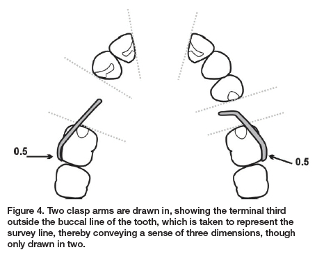
Now draw the position of the clasp arms on the diagram. For the sake of clarity, and to aid communication with the dental technician, it is recommended that you and your technician understand that, however you draw the clasp, the terminal third will be in the undercut. For the drawing in this series, the line representing the buccal surface of the teeth will be taken to represent the survey line, so by drawing the terminal third of the clasp outside that line, it is understood that it is below the survey line (Figure 4). Note that according to the clasp guidelines for wrought wire (see Part 3),5 the undercut to be used on a molar is 0.5mm.
Note also that all active clasps must be reciprocated, and this must be borne in mind when carrying out the next step.
For a framework-based denture
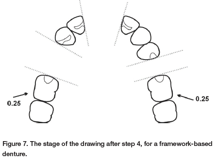
At this stage, as the clasps are part of the framework, it is only necessary to ensure that the correct undercuts are specified. For cast clasps, the undercut should be no more than 0.25mm, so this must be noted because the undercut on the molars is 0.5mm and therefore the technician must be aware to use the portion of the undercut that corresponds to 0.25mm, which will be nearer the survey line.
Step 5. Connect the separate components
This is now where the design of the major connector will differ significantly depending on the base materials to be used.
For an acrylic base
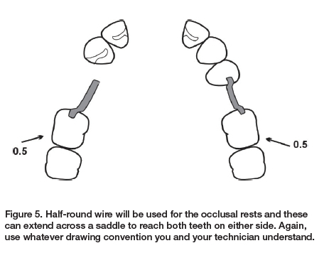
The principle to follow is to try not to cover all gingival margins if at all possible. As a rule of thumb, to prevent hyperplasia at least two teeth should remain uncovered if possible, and never just one tooth. Clearly clasps need to be reciprocated by the inner surface of the acrylic base, and cingulum rests need to be covered. Occlusal rests will be in half-round wire and these can be drawn in first (Figure 5).
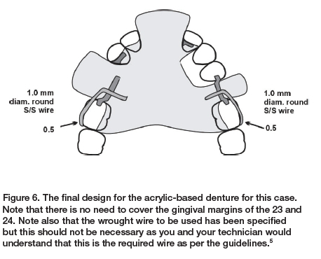
This situation currently has cingulum rests on each of the lateral incisors. The rest on the 22 is absolutely necessary, even if it requires a restoration; however, the rest on the 12 is not necessary as there must be a rest on the 13. This does not prevent the base having to cover the gingival margin of the 12, but does prevent a rest preparation (the 12 will still have a guide plane prepared, of course). There is no clasp on the 24 and no rest on the 23, so the gingival margins of these teeth do not need to be covered, and the second molars also do not need to be covered. Joining everything up, then, gives us the final design (Figure 6).
For a framework-based denture
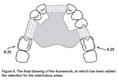
Because the framework is the major connector with all the components in one unit, without, of course, the teeth and acrylic for the edentulous areas, the previous step would have been left with identifying only the necessary undercuts (Figure 7). Similar decisions need to be made for the cingulum rest on tooth 12. In this case, it has been decided to place a rest there (Figure 8). Note the difference in the gingival coverage between this design and that of the acrylic-based denture in Figure 6. In this case, there is no gingival coverage at all, one of the major advantages of framework-based dentures.
Step 6. Ensure that there is horizontal and rotational stability
With edentulous areas on either side of the arch, as well as an anterior area, there is unlikely in this case to be any concern about either horizontal or rotational stability. This step is a mere check in this case, but would be important in other designs, and will be covered in the last part of this series, where examples of designs for all Kennedy classifications will be shown.
Step 7. Record the prescription, preferably as a drawing
This would seem self-evident, but unfortunately the evidence is that this is seldom done, and hence the reason for this series of papers. Even though in the US, for example, it is mandatory to complete a work authorisation form6 one study found that more than 88% of dental laboratories reported that the dentist's communication to them was lacking7 and similar findings have been reported elsewhere.8-10
CONCLUSION
It is suggested here that by following a few simple steps, it is possible to quickly design an RPD that conforms to evidence-informed principles and that there is therefore no excuse for clinicians not doing this. At the very least the design phase could be done in consultation with the dental technician and there must be clear communication between the two at all times.
The principle suggested here should result in hygienic designs, no matter what material is used, but, in either case, the removable partial denture is a foreign body with many surfaces to attract biofilm. A critical review of the relationship between RPDs and periodontal health concluded that while there is no agreement on the ideal RPD design, clinical trials have shown that periodontal health can be maintained if the basic design principles are followed, together with frequent recalls for oral hygiene and prosthetic maintenance.11
REFERENCES
1. Owen CP. Fundamentals of removable partial dentures. 5th Edition. Available at https://www.appropriatech.com Accessed 5 September 2023 [ Links ]
2. Owen CP. A simplified approach to designing removable partial dentures. Part 2. The biomechanical basis of support. SADJ 2023 [ Links ]
3. Owen CP. A simplified approach to designing removable partial dentures. Part 3. The biomechanical basis of retention. SADJ 202? [ Links ]
4. Suenaga H, Kubo K, Hosokawa R, Kuriyagawa T, Sasaki K. Effects of occlusal rest design on pressure distribution beneath the denture base of a distal extension removable partial denture - an in vivo study. Int J Prosthodont. 2014;27(5):469-71. doi: 10.11607/ljp.3847 [ Links ]
5. Owen CP, Naidoo N. Guidelines for the choice of circumferential wrought wire and cast clasp arms for removable partial dentures. Int Dent J. 2022;72(1):58-66. doi: 10.1016/j.identj.2021.01.005 [ Links ]
6. Bohnenkamp DM. Removable partial dentures: clinical concepts. Dent Clin North Am. 2014;58(1):69-89. doi: 10.1016/j.cden.2013.09.003 [ Links ]
7. Taylor TD, Matthews AC, Aquilino SA, Logan NS. Prosthodontic survey. Part I: Removable prosthodontic laboratory survey. J Prosthet Dent. 1984;52:598-601 [ Links ]
8. Farias-Neto A, Silva RSG, Cunha Diniz da A, Batista AUD, Carreiro AdaFP. Ethics in the provision of removable partial dentures. Braz J Oral Sci. 2012;11:19-24 [ Links ]
9. Haj-Ali R, Al Quran F, Adel O. Dental laboratory communication regarding removable dental prosthesis design in the UAE. J Prosthodont. 2012;21(5):425-8. doi: 10.1111/j.1532-849X.2011.00842.x [ Links ]
10. Tulbah H, AlHamdan E, AlQahtani A, AlShahrani A, AlShaye M. Quality of communication between dentists and dental laboratory technicians for fixed prosthodontics in Riyadh, Saudi Arabia. Saudi Dent J. 2017;29(3):111-16. doi: 10.1016/j.sdentj.2017.05.002 [ Links ]
11. Petridis H, Hempton TJ. Periodontal considerations in removable partial denture treatment: a review of the literature. Int J Prosthodont. 2001;14(2):164-72 [ Links ]
 Correspondence:
Name: Prof CP Owen
Tel: +27 83 679 2205
Email: peter.owen@wits.ac.za
Running title
A simplified approach to designing RPDs

