


Serviços Personalizados
Artigo
 Inglês (pdf)
 Artigo em XML
 Referências do artigo
Indicadores

Links relacionados
-
 Citado por Google
 -
 Similares em Google
Compartilhar

 Permalink
South African Dental Journal
versão On-line ISSN 0375-1562
versão impressa ISSN 0011-8516
S. Afr. dent. j. vol.77 no.4 Johannesburg Mai. 2022
http://dx.doi.org/10.17159/2519-0105/2022/v77no4a5
RESEARCH
Criteria that must be considered in order to optimise the success of computer aided designed and computer aided manufactured (CAD/CAM) restorations
NW van Reede van OudtshoornI; C BradfieldII; LM SykesIII
IBChD, PDD, PG Diploma in Prosthodontics, Private Practitioner, University of Pretoria
IIB Tech, BChD, Dip Aesthetics; Registrar Department of Prosthodontics, University of Pretoria
IIIBSc, BDS, MDent, IRENSA, Dip Forensic Path, Dip ESMEA; Head of Department of Prosthodontics, University of Pretoria. ORCID Number: 0000-0002-2002-6238
ABSTRACT
Several factors influence the success or failure of ceramic dental restorations, and need to be considered and understood prior to embarking on these restorations. It is incumbent on the clinician to have an in-depth knowledge on the science of ceramic materials, current bonding agents and techniques, understanding and working proficiency of computer aided design and computer aided manufacture (CAD/CAM) computer hardware and software, an appreciation of oral biology, the role of occlusion and occlusal schemes, as well as recognition and management of patients with parafunctional habits. This paper will cover the principles of cavity preparation and tooth preparation designs, maintenance and / or achievement of inter-arch stability, preservation of marginal integrity, provision of occlusal stability, and digital impression techniques required to optimise accuracy. Provision of a chairside manufactured CAD/CAM dental restoration requires dentists to perform both the clinical and the laboratory aspects of the procedure. The responsibility for the quality of the final restoration thus rests in their hands alone and it is their duty to ensure they are adequately trained and skilled in all aspects of CAD/CAM if they wish to make it part of their practices.
INTRODUCTION
Since the introduction of the CEREC® I system in 1987, CAD/ CAM manufactured dental restorations have become a large component of many modern dental practices. However, the success of these procedures is dependent on the expertise, knowledge and skills of the operator. There are a number of factors that contribute to their quality, clinical acceptability and long term durability. These include:
1. Cavity preparation / tooth preparation design
2. Inter-arch stability
3. Marginal integrity
4. Occlusal stability
5. Digital impression accuracy
1. Cavity preparation and tooth preparation design
''The benefits of a smooth, crisp, cavity preparation for CEREC® restorations cannot be overstated. Excellent CEREC® restorations are the result of excellent preparations." - Prof. Dennis Fasbinder (personal communication).
The tooth preparation or cavity design criteria that must be considered in order to optimise the success of CAD/CAM restorations can be divided into 3 main categories:
1.1 General preparation guidelines.
1.2 System (hardware) guidelines.
1.3 Material guidelines.
1.4 General preparation guidelines
In all CAD/CAM preparations there are key design principles that have to be adhered to. The margins must be precise, well-defined, rounded and clearly visible, and there must be even tooth reduction. The amount of reduction will then be dictated by the:
• Preparation type (Crown, Inlay/Onlay, Veneer, Implant)
• Restorative material to be used
• Minimal thickness needed for the material and restoration type
• Preparation form and shape
• Surface that is being bonded to
• Adhesive luting material and procedure
• Occlusion and presence of other parafunctional habits1
Prior to embarking on the preparation for bonded restorations the clinician needs to consider the durability of the tooth to be restored, and conduct a biomechanical analysis before and during the cutting.1 The CAD/CAM tooth preparations must ensure that there are smooth flat surfaces, few retentive features, minimal taper (3° to 6° degrees), visible round internal angles and a large modified shoulder to allow the milling machine burs to reproduce these features accurately. Minimal invasive tooth preparations are desired, however biomechanical analyses may dictate the need to reduce or remove unsupported tooth structure / cusps, and areas with doubtful stability.1 Ahlers et al 5 and Arnetzl and Arnetzl 2,3,4 have described 8 guidelines to follow when preparing teeth for bonded all-ceramic restorations.
• Keep the basic geometry simple. The ideal tooth preparation should have dentine that is still surrounded by enamel.
• There must be an appropriate and uniform thickness of reduction to ensure the same thickness of the restoration (minimum 1.5-2mm).1
• There must not be any corners or sharp edges, and aim for soft transitions between concavities and convexities.
• Avoid tensile stresses and try transform tensile stresses to compressive strengths by changing the preparation design.
• Stress peaks and sudden changes in cross-section should be avoided by providing soft and smooth transitions.
• Minimize notch stresses.
• Aim to create as large as possible contact surface with the ceramic restoration.
• Strive to end restorations in enamel whenever possible.2-5
Consideration of cusp retention will need to take into account aesthetic and functional concerns. They should be retained when there is enough tooth cusp material to support occlusal forces, and will not flex during mastication. The decision will be guided by performing a biomechanical analysis of anticipated forces and loading on the tooth before and during the tooth preparation, and evaluating the tooth during latero-trusive movements.1 Crowns on endodontically treated teeth are prepared by removing the undercuts in the pulp chamber allowing the endodontic cavity and the pulp chamber to become continuous.8,9 The success rate of endocrowns made by CEREC® III and Vita Mk II in a CAD/CAM system spanning 12 years and 55 patients was reported to be 90.5% for molars and 75% for premolars.8,9
Sectioning the enamel prisms obliquely will result in enamel being supported by dentin due to stresses that will be relocated.1 A non-retentive tooth preparation is recommended as part of the above described concept, resulting in a favourable biomechanical loading of the bonded restoration-cement-tooth complex.1
There is no consensus on the optimal internal cement space (Spacer) for adhesively luted ceramic restorations. While most agree that the cement layer (occlusal and radial spacer) needs to be as small as possible,1 there is no consensus on the optimal internal cement space.1 Greater or larger resin cement film thickness decreases the bond strength of the core material to lithium disilicate ceramics.6 Gianfranco Politano et al (2018) advocated a space of between 50-100 pm.1
However, although the suggested factory setting in the CEREC® system is 120 pm, and others have even recommended a larger spacer setting of 200 pm.6 They report this will result in a better fit, but has a higher risk for malpositioning during cementation and negligibly thinner porcelain. For onlays/inlays with a recommendations are 1.5mm occlusal thickness, a spacer of 100 pm is proposed14, as larger spaces will result in more polymerization shrinkage. In addition, the bond strength of composite cements to glass ceramics decreases with increased cement film thickness.1,7 The final preparation of the enamel is then carried out after application of immediate dentine sealing (IDS).
A recap of factors to consider when examining the CAD/CAM tooth preparation and prior to scanning:
• Ensure strict isolation and gingival retraction if necessary
• Walls should have a 6°-8° taper
• Rounded internal line angles, with smooth crisp margins and no bevels. Shoulders should be 90° and chamfers 90°-130° (Figures 1- 4 illustrate various margin designs)
• Adequate tooth reduction in all dimensions
Both the J-lipping finish (Figure 1) and knife edges (Figure 2) are unsuitable for all-ceramic crowns, because a correct, anatomical contour cannot be constructed.15 Both shoulders (Figure 1C) and Chamfers (Figure 1D) are preferred, however the stress distribution for chamfers is larger near the marginal line, which is one of their biggest disadvantages.15
Rocca et al (2015) 9 described the following clinical step-by-step protocol for the cavity preparation of bonded indirect restorations:
1. Apply local anaesthesia.
2. Check occlusal contact and aesthetic needs of the tooth (Authors comment: The occlusion should be checked with the patient in an upright position before administering the local anaesthetic. Occlusion in an upright position could differ from a supine position and the local anaesthetic could influence the bite registration.)
3. Proper shade selection.
4. Remove unsound restorations, excavate caries and prepare the cavity, but do not finish the margins at this stage.
5. Check inter-occlusal space in centric and during lateral movements.
6. Isolate the cavity with rubber dam and in cases with subgingival margins, place a metal matrix band.
7. Apply a dual bonding (DB) / immediate dentin sealing (IDS) agent and seal all of the dentin with the adhesive system following manufacturer's instructions. This procedure must also include any thin subgingival margins.
8. Light-cure bonding resins for 20 seconds.
9. Cavity Design Optimization (CDO) and Cervical Margin Relocation (CMR). This is achieved by applying a layer of composite resin to cover the dentin, fill retention grooves and relocate margins supragingivally if necessary. Lightcure each increment of composite resin for 40 seconds before adding successional layers. (Authors note: CMR does not meet the criteria of a solid shoulder that needs to absorb the compressive forces, and may compromise durability of the tooth and / or restoration.)
10. Isolate the cavity with a layer-forming glycerine gel, and light cure this again for 10 seconds.
11. Finally finish the enamel and / or composite margins with fine diamond burs, but do not expose dentin during this stage.
12. Re-check the cavity to confirm: Detailed clear margins; absence of undercuts; accessibility of supragingival margins; absence of contact between the cavity and the adjacent teeth and adequate interocclusal space in centric and during lateral movements (this can only be done after rubber dam removal).
13. The digital impression can then be taken and the restoration designed and fabricated.
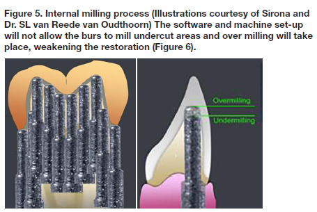
1.2 System (hardware) guidelines
The CEREC® step-burs mill the fitting surface of the ceramic blocks to correspond to the prepared tooth surface. There are 3 burs available with diameters of 0.85mm, 1.0mm, and an ultra-fine bur with diameter of 0.3mm. Figure 5 illustrates the path of movement the bur follows when grinding (cutting) the internal surfaces for crowns.
The Step bur has a 3° taper increase after every step of the bur, these being 4mm apart (Figure 7). This configuration results in formation of convergence angles of 3° - 4° after the first 4mm preparation height and a further 3° - 4° for the next 4mm preparation height

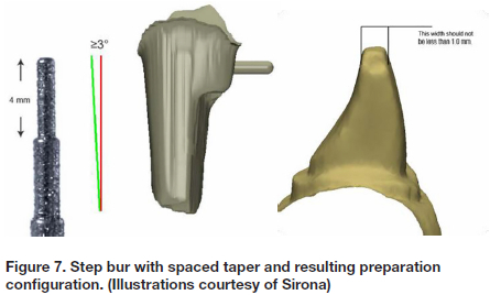
Any corners within the preparation need to have a diameter large enough to accommodate the 0.85mm and 1.0mm burs. Sharp corners, or those with diameters less than 1.0mm will either not be milled or will be undermilled, leading to restorations that do not fit properly (Figure 8 ).

1.2 Material guidelines
Material type and prepration design influences the incidence of tooth fracture.10 Restorations grinded from feldspathic porcelain are weaker than restorations made of glass-ceramic or resin-composite materials.10 Material guidelines provide clinicians with parameters of minimal reduction required to ensure adequate material thickness for any given restoration design and material type.
Dejak et al (2020) 15 compared the strength of thin walled molar crowns made of various materials , including zirconia, porcelain, gold and composite crowns. Simulated mastication, analysing contact stresses at the adhesive interface between the cement and tooth structure under the crowns were analyzed.15
The results found were:
• Equivalent stresses in the crowns, did not exceed the tensile strength of their material.
• The modified von Mises (mvM) failure criterion is used to evaluate the strength of materials under compound stress states.15 (The criterion considers the ratio between the compressive and tensile strength).
• Stresses in resin cement under Zirconia crown were 1.3 MPa. Under composite crowns 6 times higher.15
• Tensile and shear contact stress under stiffer crowns (ceramics and gold) are several times lower than under composite crowns.15
• The higher the elastic modulus of the crown material, the higher the values were of the equivalent mvM stresses in prosthetic crowns.15
• In the zirconia crown the highest stress value (51.5 MPa) was observed under the distobuccal cusp.15
• In the porcelain crown the maximum stresses concentrated on the same area although their value did not surpass 35.2MPa.15
• Under composite crowns the mvM stresses reached the value of 11.4 MPa.in the central groove.15
• In the cervical area mvM stresses were several times lower than on the occlusal surface.15
• The equivalent stresses in the crowns were 14.5 times lower than the tensile strength of Zirconia-based ceramics.
The maximum mvM stresses in the tooth structure for the zirconia crown were only 2.8 MPa, compared to that for the composite crowns were 6.4 MPa. The higher the elastic modulus of the crown, the lower the equivalent stresses in the composite luting cement and in the tooth structures. Also contact stresses decreased with the increasing stiffness of the crowns.15
Zirconia is a rigid material with little or no elastic deformation. Crowns made from this material have a high modulus of elasticity (MOE), allowing any compressive forces to be directed towards the margins /shoulders. In contrast, resin crowns are more elastic with a lower MOE allowing compressive forces to be directed towards the underlying cement, resulting in an increased risk for debonding. Finite element analysis of masticatory forces suggest that the majority of compressive forces are transferred to the shoulder areas on the crowns, and as such a shoulder marginal preparation is advocated in order to provide a large enough surface area to absorb these. A rounded shoulder is particularly suitable for the telescopic crown technique with all-ceramic primary copings.15
2. Inter-arch stability
The position of the teeth in the dental arch is determined by the size of the teeth and the amount of space available to accommodate them. Discrepancies between the mesio-distal tooth widths, and arch dimensions may be associated with tooth positional nonconformities. The size and shape of the teeth with respect to their dental arches can have implications in treatment planning and prosthetic reconstruction, as it affects the space available, dental aesthetics, and stability of the dentition. The 2 main factors accountable for dental crowding are teeth with increased mesio-distal dimensions in mouths with decreased dental arch sizes. These are factors to consider when deciding if orthodontic treatment is necessary, and whether conservative inter-dental stripping and crown recontouring would suffice, or if more invasive extraction and / or banding and / or surgical regimes are needed.21 Many cases illustrate that crowded arches have larger teeth than the normal arches and that smaller teeth, in particular mandibular incisors may be responsible for dental spacing. Furthermore, both the mesio-distal and bucco-lingual dimensions can affect dental alignment.
Crown dimensions of permanent teeth in young men with good occlusions were compared with those in persons requiring orthodontic treatment. Results showed that tooth crown dimensions (MD as well as BL) were significantly larger in subjects with malocclusions and crowded arches than in those with good occlusion. It was interesting that only the maxillary first molars, canines, and mandibular incisors were found to be different and statistically significant.21 Differences in the tooth and arch dimensions are associated with dental arch discrepancies and has implications in both restorative diagnosis and treatment planning, and must be considered when deciding on the most suitable treatment option.
Correct proximal contours and a well designed and constructed contact point is important with regards to inter-arch stability, and the success of class II restorations. Ideally there should be a tight contact area at a distance of approximately 5mm from alveolar crest, or in the area of the height of contour of the tooth. 21 Resin composite restorations show looser proximal contacts than amalgam regardless of whether a high viscosity or medium viscosity composite was used. Indirect restorations manufactured with CAD/CAM have a better potential for generating anatomic forms and ensuring the points are in the correct position, of the desired size and generate the recommended force on the adjacent teeth.12 Indirect CAD/CAM manufactured restorations have a better potential for generating anatomic forms, compared to direct resin composites, amalgam and even high viscosity composites.11
Constructing a contact point with the CEREC® system.
The manufacturers recommend use of the Equalizing method (hand polishing) method to create the ideal contact area. Before beginning, the clinician needs to know and understand the colour configurations involved in the construction of the contact points, and decide which amount of force is needed for each situation.
Note:
• Red: Represents a distance of 100 μm + into the neighbouring tooth.
• Yellow: Represents a distance of 50 to 99 into the neighbouring tooth.
• Green: Represents a distance of 1 to 49 into the neighbouring tooth.
• Blue: Represents a distance of 1 to 25 μm away from the neighbouring tooth. (The same values apply to the occlusal contacts).
• Two factors need to be considered when constructing the contact point.
They are:
• The system parameter setting. (Factory setting 25 pm)
• The colour configuration. The interface of two colours, yellow with red disappearing when digitally polished (interface approximately 99-100 or yellow disappearing on a green background. (interface approximately 49-50 pm)
• On the interface of two colours the operator can predict the distance into the neighbouring tooth accurately compared to a one colour which is unprecdictable because the colour spans a distance of 50 pm.
The recommended interface of two colours is yellow disappearing on a green background.This value might differ between systems. It is therefore important to understand the colour configuration values and set the system contact point strength values accordingly.
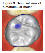
Steps to follow when constructing a contact point:
1. View the virtual model with restoration proposal from the occlusal aspect (Figure 9). Establish whether the bucco-palatal contour is convex.The distal aspect is convex whereas the mesial aspect is more flat. (Figure 9).
2. View the virtual model from the buccal side (Figure 10) and establish if the gingival-occlusal contour is convex.
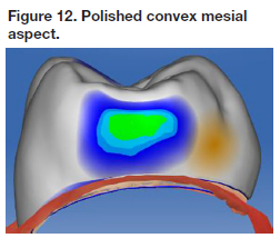
3. View the restoration proposal from the mesial aspect. (Figure 11) Polish the whole area with Form tool / Smooth to create a convex contact area viewed from the buccal as well as from the occlusal (Figure 12).


The restoration proposal with the mesial and distal surfaces convex and smooth, however the mesial contact is open and needs to be corrected (Figures 13).
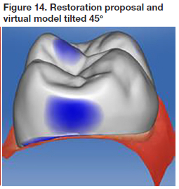
4. Once the required size of the contact has been decided upon the virtual model can be set at a 45° angle (Figure 15) and the area drawn out until the desired size is attained and the surface is convex. This final shape is attained by utilizing the Shape Anatomical tool , digitally manipulating the restoration proposal into the neighboring tooth (Figure 16). Note: The yellow band in the middle of the resoratior indicates the Shape Anatomical tool activated the middle third of the restoration. The Shape Anatomical tool is a medium mangement tool.
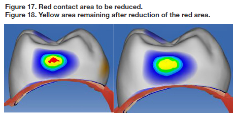
5. Final polishing is performed by turning the proposed restoration and virtual model so that it can be viewed directly from the mesial aspect. The surface is polished with the Form polishing tool on the red areas beginning at the gingival aspect and moving upwards to the occlusal aspect. (Figure 18). Note that the size that the polishing tool should be set smaller than the area to be polished (red in this case). The bucco-palatal and the gingival-occlusal dimension of the contact point must remain the same size after the polishing (Figures 18-20).
6. The yellow area is then polished until it has almost disappeared (Figure 19) and there is a smooth interface between the next two colours. The principal contact area is green with a small dot of yellow indicating a colour interface representing a distance of 49-51μm (Figure 20). The bucco-palatal dimension as well as the gingival-occlusal dimension has stayed the same.


3. Marginal integrity
Poor marginal fit will allow degradation of the cement in the oral environment, resulting in micro leakage, marginal discolouration, recurrent caries and periodontal disease.1 In addition, increased marginal discrepancy MD values reduce the fracture resistance of the crown and the veneering porcelain. There is no clear scientific evidence or general consensus on the maximum clinically acceptable MD, with suggested values ranging between 50 μm and 200 μm, but in theory it should be small enough to prevent ingress of saliva and/or lactic acid, the by-product of bacterial metabolism. According to Kramer et al, restorations with marginal discrepancies in the region of 100 μm are clinically acceptable,13
The marginal gap (discrepancy) for the CEREC® I system that was first introduced in the 1980's was approximately 300 μm, but this was refined and improved in CEREC® II to be 200 μm. Currently, the clinical goal for a cemented restoration is a MD value ranging 25 μm to 40 μm.13 CAD/CAM manufacturers aim to produce dental restorations within these values. The comparison between CAD/CAM technology and traditional fabrication processes with respect to marginal adaptation has been extensively studied.13 A point to remember is that milling machines are not able to produce the contour of the restoration in areas that are smaller than the diameter of the milling burs.13
The marginal adaptation of indirect restorations is affected by preparation design, impression technique and thickness of the luting agent.13 In the early days of CAD/CAM, impressions were taken using polyether materials as these had performed well since the middle 1960's. Their main advantages include a relatively fast chair side setting time, good flow and detail reproduction, high Modulus of Elasticity (MOE), and hydrophilic.14 Despite these favourable characteristics, there were still many other factors that could cause distortion of the models, including operator's ability and impression technique, temperature variations, movement during setting period, laboratory handling of the impressions, cast pouring procedures and gypsum expansion.14 Digital scanning overcame many of the complications associated with conventional impression taking. They were not superior to conventional impressions when comparing reliability, accuracy and detailed reproduction, but do have the advantage of reduced clinical chairside time, patient and operator preference and improved patient comfort.14
The preparation margin must ideally be located in enamel to ensure long term stability to the large dentin adhesive surface.1 Restoration margin exposed to occlusal wear can result in extensive marginal discrepancies, especially in partial crowns that do not cap all cusps. It is imperative that the fit and adaptation at the occlusal surface is near to perfect with the luting marginal gap being be as small as possible.1 (The CEREC® factory setting for this value is programmed on 60μηη and is referred to as the "holy zone" that represents the first 400μπΊ from the preparation margin inwards.)
Onlay preparations designed with a modified shoulder provides a better marginal adaptation compared to flat cuspal reduction. The presence of lipped finishing lines and spikes on finishing lines may cause problems in the adaptation of CAD/CAM crowns and therefore the margins and internal line angles should be carefully evaluated and sharp angles eliminated.14
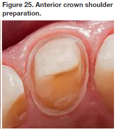
In Figure 23, tooth 46 onlay has a shoulder preparation of approximately 1.0mm and margins that are smooth due to the use of an oscillating blade with 50μm grid. The 4 mandibular anteriors in Figure 24 were prepared with a shoulder of 1.0mm lingually preserving as much enamel as possible, and a deep chamfer of 1.0mm labially. Tooth 11 in Figure 25 was also prepared with a shoulder of 1.0mm lingually for enamel preservation, and a deep chamfer of 1.0mm labially. The crown height was >4mm.


4. Occlusal stability
Occlusal functional stresses are responsible for the inherent vulnerability of ceramic restorations and need to be compensated for by having a thicker restorative layer occlusally, as well as use of the correct adhesive bonding system.10 This often entails sacrificing enamel and dentin thereby weakening the tooth structure.10 Thicker overlay restorations are stronger and have higher static fracture strength than the more conservative ones. However this comes with a biological cost, as they also display an increased incidence of failures, which are generally more dramatic and irreversible due to the thinner and weaker dental tissues underneath them.10 Minimal occlusal restorative thickness required depends on the intrinsic mechanical features (static and dynamic reaction to stress) of each different material, and is brand dependant.10 It is recommended to have at least 2mm occlusal reduction for lower strength ceramics (Vita MK II) and 1-1.2 mm for higher strength ceramics.(IPS e-max CAD).10 These dimensions are limited to monolithic ceramic restotrations as layering could result in including imperfections that weaken the material.10
Occlusal coverage is recommended for cavity walls of 1mm or thinner, while for those with an "intermediate thickness" (12mm), the occlusal factors such as tooth position, presence of para-functional habits and and lateral guidance (canine or group guidance) should guide the final decision.10
The pressence or absence of marginal ridges can also play a role in the final strength of the residual wall, especially in endontically treated teeth.10 When designing the crown form, the clinican may use the correlation method or the dental database (library) method.
• Correlation method. An optical impression of the tooth is taken prior to preparation of the tooth. The software copies the pre-operative image and final restoration proposal will then be a copy of the unprepared tooth.
• Dental database (library method). The software extrapolates information from the teeth captured in the optical impression, mesial and distal from the prepared tooth. A proposal of the restoration will then be digitally constructed. In the case of inlays/onlays, the software of the system utilizes the information of remaining unprepared tooth structure to digitally construct and propose the restoration. CAD/CAM crowns designed using the correlation method are easier and more accurate to fabricate and have better occlusal relationships than those designed using the library method, especially at the initial fit.17 They also had relative occlusal force (ROF) that were higher than that of crowns designed using the library method and correlated positively with the force of the tooth before preparation.17
5. Digital impression accuracy
Conventional Poly Vinyl Siloxane (PVS) impressions and gypsum dies have inherent problems and varying degrees of accuracy due to the many factors described in point 3 above.22 Digital scanning of tooth preparations offered clinicians a faster, more user friendly and reportedly more accurate alternative, even when highly accurate impression materials were used.20 The precision of digital impressions continues to develop and improve with each new scanner that comes onto the market. For example the new CEREC® Bluecam camera can record details of as fine as 19 μηι in single-tooth images, while quadrant images can be taken with accuracy of approximately 35 μιτη. The newer devices are also more user friendly as they have a built-in shake detection in the automatic capture mode. While technology has certainly aided clinicians, the quality of the optical impressions (scans) and the images obtained depends on the operator's experience, complexity of the preparation design, position of the teeth and gingival margins, as well as the compliance of the patient.14
Most digital impression systems can record full dental arches,19 but show a higher local deviation of the dental arch compared to conventional impression methods.19 Errors increase in the transition from a single crown to partial prosthesis up to a full arch scan. 21 Fortunately full arch digital impressions are not regularly required in dental practice where the majority of cases involve sections of the arch with a limited number of preparations. There are also notable differences in accuracy between different scanners and systems and clinicians need to take cognisance of this and study peer reviewed scientific papers on each before purchasing this costly equipment. Studies have shown significant differences in terms of scan time and number of images captured per scan, between default resolution and high resolution in terms of accuracy on the crown preparation cavo-surface finish line, and depending on the tooth surface, with the distal surface demonstrating the lowest accuracy.17
The high-resolution mode of the software obtains more data over a longer time (increased scanning time) , but does not benefit scan accuracy.16 Tooth preparation and surface parameters do affect accuracy.16 Crown preparation quality as measured by tooth surface smoothness has an effect on CAD/CAM-fabricated crowns, the scanner does not.16
Indirect digital scanning techniques present a smaller marginal discrepancy compared to direct scanning techniques.14 Digitizing conventional impressions with extroral scanner is not more accurate than direct intraoral scanning.18
CONCLUSION
Provision of a chairside manufactured CAD/CAM dental restoration requires dentists to perform both the clinical and the laboratory aspects of the procedure. The responsibility for the quality of the final restoration thus rests in their hands alone and it is their duty to ensure they are adequately trained and skilled in all aspects of CAD/CAM if they wish to make it part of their practices.
REFERENCES
1. Gianfranco Politano,Bart van Meerbeek, Marlene Peumans. Nonretentive Bonded Ceramic Partial Crowns: Concept and Simplified Protocol for Long-lasting Dental Restorations. J-Adhes Dent 2018; 20: 495-510. doi.10.3290/j.jad. a41630 [ Links ]
2. Arnetzl GV, Arnetzl G. Design for all-ceramic inlay materials. Int J Comp Dent 2006 Oct;9(4): 289-298. [ Links ]
3. Arnetzl GV , Arnetzl G :Biomechanical examination of inlay geometries-is there a basic biomechanical principle? Int J Comp Dent 2009; 12(2): 119-130. [ Links ]
4. Arnetzl GV, Arnetzl G.; Reliablitly of non-retentive all-ceramic CAD/CAM overlays. Int J Comp Dent 2012; 15: 185-197. [ Links ]
5. Ahlers M. Oliver, Mörig G, Blunck, U, Hajto J, Pröbster L, Franckenberger R. Guidelines for the preparation of CAD/CAM ceramic inlays and partial crowns. Int J Comp Dent 2009; 12: 309-325. [ Links ]
6. Isil Cekic-Nagas , Senay Canay, Erdal Sahin.Bonding of resin core materials to lithium disilicate ceramics: the effect of resin cement film thickness. Int J Prosthodont. Sep-Oct 2010;23 (5): 469-471 [ Links ]
7. Ayaka Shirasaki (DDS), Satoshi Omori (DDS, PhD), Chiharu Shin (DDS, PhD), Mina Takita (DDS), Reina Nemoto (DDS, PhD), Hiroyuki Miura (DDS, PhD); Influence of occlusal and axial tooth reduction on fracture load and fracture mode of polyetheretherketone molar restorations after mechanical cycling.Asian Pac J Dent 2108 ; 18: 29-36. [ Links ]
8. Salah A Yousief, Faysal Abdullah Aman, Maher Mohammed Almutairi, Ahmed Eid Dafe Allah Alhejali, Faisal Mahmoud Alshehri, Khalid Mohammed Saeed Almutairi, Ola Mohammed Rambo, Abeer Mohammed Rambo, Anmar Essam Kattan, Ali Abdulrahman Alsufyani and Abdullah Milfi Alonazi. CAD/CAM Endocrowns Vs. Crowns" EC Dental Science 19.2 (2020) :1-7 [ Links ]
9. Giovanni Tommaso Rocca (DMD), Nicolas Rizcalla (DMD) Ivo Krejci, Prof(DMD)PD,DidlerDietschi, (DMD,PhD,PD) Evidence-based concepts and procedures for bonded inlays and onlays. Part II. Guidelines for cavity preparation and restoration fabrication. Vol. 10 Number 3 2015 [ Links ]
10. Shahed Ali M. Al Khalifah, The Influence of Material Type, Preparation Design and Tooth Substrate on Fracture Resistance of Molar Onlays.Thesis submitted in partial satisfaction of the requirements for the Master of Science in Oral Biology. [ Links ]
11. Besrour A, Nasri S, Hassine N, Harzallah B, Cheriff M, Hadyaoui D.Contribution of Ceramic Restorations to Create an Optimal Interproximal Area. Journal of Clinical and Medical Images ISSN: 2640-9615. [ Links ]
12. AZAR Basel, ECKERT Steve, KUNKELA Josef, INGR Tomas , MOUNAJJED Radek. The marginal fit of lithium disilicate crowns: Press vs. CAD/CAM Braz Oral Res. 2018;32 [ Links ]
13. Fernanda Ferruzzi Lima (DDS, MS, PhD), Constantino Fernandes Neto, José H Rubo(DDS, MS, PhD), Gildo Coelho Santos Jr. (DDS, MS, PhD) and Maria Jacinta Moraes Coelho Santos (DDS, MS, PhD) Marginal adaptation of CAD/CAM onlays: Influence of preparation design and impression technique. Journal of Prosthetic Dentistry 2017 [ Links ]
14. Sorin Porojan, Florin Topalã, Lliliana Sandu: Finite Element Analysis of Molars Restored with Ceramic Crowns. Corpus ID: 18067904:Published 2012. [ Links ]
15. Beata Dejak, Andrzej Mlotkowski, Cezary Langot. (Department of Prosthetic Dentistry, Medical University of Lodz , Poland) Three-dimensional finite element analysis of molars with thin-walled prosthetic crowns made of various materials.2011 SciVerse ScienceDirect.Elsevier.com journals. [ Links ]
16. Asher Chiu, Yen-Wei Chen, Juri Hayashi Alizera Sadr Accuracy of CAD/CAM Digital Impressions with Different Intraoal Scanner Parameters. Department of Restorative Dentistry, University of Washington School of Dentistry, Seattle 2020 [ Links ]
17. Rui Zhang(DDS), Qian Ding (DDS), Yuchun Sun(DDS, PhD), Lei Zhang, (DDS, PhD) and Qiufei Xie, (DDS, PhD): Assessment of CAD/CAM zirconia crowns designed with 2 different methods: A self-controlled clinical trial: JPD 2018; p 686-692. [ Links ]
18. Andreas Ender (Dr. med. Dent), Albert Mehl (Prof. Dr. med.dent.)Full arch scans: Conventional versus digital impressions-An in-vitro study. Int Journal of Comp Dentsitry.Jan 2011 [ Links ]
19. A. Ender (Dr. med.dent.), M. Zimmerman (Dr. med.dent), A. Mehl (Prof.Dr.med.dentrer.hum.biol) Accuracy of complete-and partial-arch impressions of actual intraoral scanning systems in vitro. [ Links ]
20. Francesco Guido Mangano, Uli Hauschild, Giovanni Veronesi, Mario Imburgia, Carlo Mangano and Oleg Admakin. Trueness and precision of 5 intraoral scanners in the impressions of a single and multiple implants:a comparative in vitro study.BMC Oral Health, (2019) 19-101 [ Links ]
21. S. Faruqui, M. Fida, A. Shaker.:Comparisson of tooth and arch dimensions in dental crowding and spacing. POJ 2012:4(2)48-55 [ Links ]
22. A, Mehl, A. Ender. W. Mörmann, T. Attin.(2009) Accuracy of testing a new intraoral camera. JJCD,2012(1):11-28 [ Links ]
 Correspondence:
Leanne Sykes
Head of Department of Prosthodontics
University of Pretoria
E-mail: Leanne.sykes@up.ac.za
Author contributions:
1 . Nic Van Reede Van Outshoorn: 60%
2 . Charles Bradfield: 20%
3 . Leanne Sykes: 20%

