


Serviços Personalizados
Artigo
 Inglês (pdf)
 Artigo em XML
 Referências do artigo
Indicadores

Links relacionados
-
 Citado por Google
 -
 Similares em Google
Compartilhar

 Permalink
South African Dental Journal
versão On-line ISSN 0375-1562
versão impressa ISSN 0011-8516
S. Afr. dent. j. vol.72 no.10 Johannesburg Nov. 2017
http://dx.doi.org/10.17159/2519-0105/2017/v72no10a3
RESEARCH
A pilot study investigating the presence of voids in bulk fill flowable composites
R MulderI; N MohammedII; A du PlessisIII; SG le RouxIV
IBChD(UWC), MSc(Dent)(UWC). Department of Orthodontics and Paediatric Dentistry, Faculty of Dentistry, University of the Western Cape
IIBChD(US), BScHons(US), MSc(US), PhD(US).. Department of Orthodontics and Paediatric Dentistry, Faculty of Dentistry, University of the Western Cape
IIIMSc(US), PhD(US). CT Scanner Facility, Stellenbosch University, Stellenbosch
IVMSc(US). CT Scanner Facility, Stellenbosch University, Stellenbosch
ABSTRACT
OBJECTIVE: To investigate the presence of voids in bulk fill flowable composites.
METHODS: This study investigated two well-known bulk-fill flowable composites, Smart Dentin Replacement (SDR) (Dentsply/Caulk, Milford, Germany) and Filtek bulk fill flowable (FBF) (3M ESPE, Minnesota, USA). Three ampules of each material were randomly selected. The ampules were subjected to 3D Micro-CT (General Electric Phoenix V|Tome|X L240) reconstruction in order to assess the presence of any voids within the ampules.
RESULTS: Voids were present in all the ampules. The total void percentage for each group of three ampules was found to be SDR : 1.147 % and FBF : 0.0424 %. There was a significant difference between the volume of voids for SDR and FBF, p-value=0.003924.
CONCLUSION: Voids were found in the randomly selected samples of bulk-fill flowable composites. This is undesirable and manufacturers should be urged to ensure that no voids are present, or at least are minimized in the ampules of material.
Keywords: Voids, bulk fill flowable composite, 3D Micro-CT reconstruction, Displacement vector fields.
INTRODUCTION
The presence of voids between incremental layers of composite material has an adverse effect on the flexural strength of the restoration.1 Manufacturers of bulk fill flowable composites advocate that these materials be placed in a single layer of a thickness of 4mm. This technique appeals to many clinicians, as not only is the restoration being placed faster compared with incremental packing, but the risks for the entrapment of impurities and voids are also reduced.2
The manufacturers' instructions for both composite and traditional flowable composites recommend that when an incremental layering technique is used, the layers should be of 2mm thickness. Investigations on the volumetric change of bulk fill flowable composites (Smart Dentin Replacement (SDR), Filtek bulk fill flowable (FBF), Venus bulk fill (VBF) compared with universal composites have resulted in similar percentages of volumetric shrinkage.3,4
Voids can be included inadvertently in the material by the manufacturer or by the clinician during restoration placement,5,6 and have been a concern since the hand-mixed chemically cured composites.7 At that stage, voids were assessed by visualisation of sections of 300µm. thickness under a stereomicroscope. The limitation of that study was that only twenty-five percent of the surface could be assessed as this was all that was visible. A mathematical equation was then used to estimate the total number and percentage of voids in the sample as a whole, which suggested that void sizes ranged between 10 and 175µm. The conclusion was that the number of small voids, between 10 and 40µm, increased during the spatulation of chemically cured composites7 Contemporary studies reported the percentage of voids in paste systems as ranging from less than 1% to 2-3%.
Voids in glass ionomers were assessed using only one sample of each material and visualisation of 40µm thick sections under a stereomicroscope.9 Three randomly selected areas (64.75mm2) were assessed in each sample, under 117.6 magnification.9
A limitation of the methodologies of these studies was that the whole sample was not assessed and thereafter, the "total assessment of voids" had to be mathematically predicted.7,9
With the development of the 3D Micro-CT (high-resolution micro-computed tomography) the whole sample could be assessed, thereby overcoming the limitations of the mathematic estimation of other techniques. The effectiveness and accuracy of the 3D reconstruction has been established as a non-destructive and accurate visualisation technique for marginal adaptation and volumetric change.10 3D Micro-CT reconstruction has also previously been applied successfully in the assessment of voids in glass ionomer.11
The incorporation of voids into a restoration may be due to the technique of condensing and smearing the material into the cavity by the clinician.12 It has been shown that the higher the viscosity of the composites the more difficult it becomes to condense it into the prepared cavity. This is mainly due to the physical properties of the material i.e. it may be too thick, sticky or dry and thus be more resistant to accurate adaption to the prepared cavity.13
The clinician may attempt to reduce the incorporation of voids through careful condensation and by avoiding smearing of the composite against the walls of a cavity preparation.12
The short- and long-term effects of the presence of voids in materials are varied and depend on the volume, number and location of the voids. Voids present in the material as produced by the manufacturer have been shown reduce load-bearing capacity in the oral environment.14 The compressive strength of single paste composites has been reduced with a resultant lower compressive fatigue limit. This is directly due to internal stresses, which are concentrated around the voids.15,16 Earlier two-paste and single-paste composites were shown in the long term to demonstrate a decreased resistance to wear if the void were to be exposed to the occlusal surface.17 A decreased micro-tensile bond strength and marginal discoloration with microleakage has been observed,12,18 irrespective of whether the voids were within the adhesive layer19 or within the composite.20 Voids located at the tooth-restoration interface could be mistaken as secondary caries due to the radiolucency of the defect.21 An in vitro study showed that bacteria accumulate in voids22 and an SEM analysis of three-year-old resin restorations indicated bacterial collection in the exposed surface pores of the restorations.23
It was postulated by McCabe (1987) that if the manufacturers were to provide void-free two paste- and single-paste composites the longevity of the restoration exposed to continuous compressive fatigue will be increased.15 The prevention of void inclusion by the clinician is equally as important as receiving a void-free material from the manufacturer.15 The high viscosity and stickiness of the packable composites can pose a risk for void inclusion into the restoration by the manufacturer or by the clinician during 2mm incremental layering condensation.23,24 The advent of bulk-fill flowable composites offers a potential solution as many clinicians place these materials in 4mm increments as recommended by the manufacturer.
The present study aimed to provide an assessment of the presence of voids in bulk-fill flowable composites and an overview of the literature on voids in dental composites.
MATERIALS AND METHODS
Materials:
This investigation evaluated two bulk-fill flowable composites and compared the volumes of voids present in three ampules of the materials. The SDR and FBF material ampules were selected due to their popularity on the local dental market.
Material test groups:
1.Filtek bulk fill flowable (FBF) (Universal Shade) (3M ESPE, Minnesota, USA, Lot 4861U).
2.Smart Dentin Replacement (SDR) (Universal Shade) (Dentsply/Caulk, Milford, Germany, Lot 0625).
3D Micro-CT scan and reconstruction:
3D Micro-CT scans were completed with a General Electric VTomex L240 system.25 The ampule scans were done using 120kV and 160µA for X-ray generation at 20µm voxel size. Data analysis was performed in Volume Graphics VGStudioMax 3.0. The procedure applied to scan the ampules was devised specifically for this application according to the requirements, which involved measuring the volumetric porosity in the ampules and the total volume of dental material in the ampules.
The voids within the unused ampules were detected by the algorithm "VGDefX", as a defect analysis function with a relative deviation value of -2.
Statistical analysis.
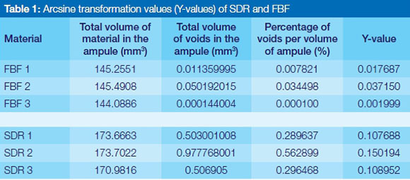
In order to perform the statistical analysis for the differences of the means on a relatively small sample size of three ampules per material group, it was essential to produce a variance stabilising transformation of the variables. For the purpose of this investigation an "arcsine transformation" was applied to the Volume of the voids / Volume of the ampule to produce the Y-values, calculated with the formula: Y = 2arcsin√p, where p is a proportion (Table 1).
RESULTS
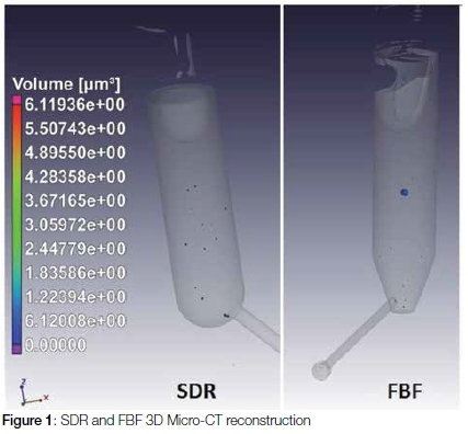
The 3D Micro-CT reconstruction was used as a non-destructive method for the investigation of the material within the bulk-fill flowable composite ampules. The 3D Micro-CT could accurately determine the volume of individual voids and the sum of all the voids in mm3 (Figure 1. Table 1, 2).
Each of the randomly selected ampules had varying volumes of material. The percentage of the voids per volume of material in the ampules was calculated mathematically, using the formula: Volume Percent = 100 x Volume of voids / Volume of ampule.
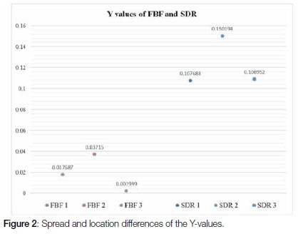
The spread and the differences in location of the Y-values for the SDR and the FBF ampules of the arcsine transformation values (Y-values) are represented in Figure 2. The t-test of significance of differences of the means indicated a significant difference: t=-5.9827, df=4, p-value=0.003924 between the material groups SDR and FBF.
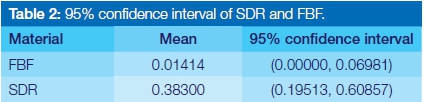
The advantage of the transformed variables was that the confidence limits could be calculated with the samples pooled within the SDR and FBF groups for variance calculations based on df=4. The confidence limits represented in Table 2 were obtained using the transformed variables and mean values of the percentage of voids within the ampule at a 95% confidence limit.
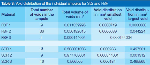
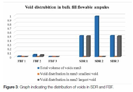
The randomly selected samples from SDR and FBF reviewed in this study showed that there were fewer voids in total for the SDR (34 voids) test group compared with the FBF (46 voids) test group. The total volume of voids in percentage for the three ampules from each manufacturer were however greater for SDR (1.147 %) in relation to FBF (0.0424 %). The smallest, largest and total volume of voids per ampule was represented in relation to the volume of the material inside the ampule Table 3, Figure 3.
DISCUSSION
The clinical relevance of the voids in relation to the longevity of the restoration and the post-operative complications are the most important considerations that the clinician should take into account. Early single-paste systems that were light-cured had a mean void size of >0.8µm where water sorption occurred into the void.26 Voids in the final restoration affected the solubility as well as the colour of the dental restoration due to the water sorption.26 Inherently, single-paste light activated composites were shown to contain voids that were close to the percentage found in the SDR and FBF ampules. The single-paste light activated composites had voids present to a percentage of 0.05-1.5% per volume.7
The presence of voids within composites result in differences in internal stress development. The stress development varies according to the location of the void in the restoration. In the event that the void is located at the restoration/tooth interface, the volumetric shrinkage will have a negative effect in the immediate area of the void due to the stress development16 around it, resulting in an increased susceptibility for adhesive failure of the restoration.19 This stress development is due to the force distribution within the material as a result of the volumetric shrinkage of the material on the void.16
Besides the stresses generated within the materials, by volumetric shrinkage and voids, the restorations are subjected to occlusal forces that could lead to the formation of cracks during loading. The crack formation has been found to be initiated and potentiated at areas where the voids are incorporated into the composite restorations.14,20
In addition, the voids incorporated in the ampules during manufacturing pose a threat to the longevity andshelf life of the material. Voids can cause oxygen inhibition on the surrounding material in the ampule.27,28 The risk of inhibition is subject to the volume of voids present. In the case of SDR and FBF, the percentage of voids to material was small. However, due to the void inducing oxygen inhibition27,28 and the fact that resin in replaced by air, a slower volumetric shrinkage could occur. The combination of the voids and oxygen exposure during restoration placement has been found to be a contributing factor to a decreased strain on the adhesive layer.27 It was postulated that in the cement used for inlays, where only thin layers of up to 200µm are used, t there might be positive effects to having voids. The rationale was that voids reduce the adhesive and cohesive failure significantly as they may serve as a free surface of 1mm2/mm3.27 Post-operative dentine sensitivity and micro-leakage at the marginal interface of the cement if voids were present was not considered when the that conclusion was reached. An in vitro study on pre-molars with GV Black Class II preparations, reached the conclusion that 16 of the 35 restorations had voids in the gingival wall within the adhesive or within the composite, compared with no voids at the axial walls.19 The location of the void incorporation is important since a review of the literature has shown that, especially for composite restorations,, the presence of voids at the tooth/restoration interface and within the material itself poses problems. A micro-leakage study with SDR indicated that most of the prepared specimens were shown under stereomicroscope evaluation to have voids in the material.29 There is scope for extensive research on voids in composites, in particular bulk-fill composites that are packed in 4mm increments.
CONCLUSION
Based on the negative clinical effects that could ensue due to void inclusions in composite materials, the manufacturers should investigate filling the syringes of bulk fill flowable composites under vacuum. This technique has proven to be successful in eliminating void inclusion in composites.5
ACRONYMS
FBF: Filtek bulk fill flowable
SDR: Smart Dentin Replacement
DEFINITIONS
Void: Bubble / porosity that is present in a dental material.
Void volume: Total volume (in mm3) of voids present in the sample of dental material.
Void percentage: Total void fraction present in the sample expressed as a percentage in relation to the total volume of the dental material.
Displacement vector fields: The direction of volumetric shrinkage that takes place within a tooth that was restored with a resin composite..
References
1. Huysmans MC, van der Varst PG, Lautenschlager EP, Monaghan P. The influence of simulated clinical handling on the flexural and compressive strength of posterior composite restorative materials. Dent Mater 1996;12:116-20. [ Links ]
2. Flury S, Hayoz S, Peutzfeldt A, Husler J, Lussi A. Depth of cure of resin composites: is the ISO 4049 method suitable for bulk-fill materials? Dent Mater 2012; 28(5):521-8. [ Links ]
3. Mulder R, Grobler SR, Osman YI. Volumetric change of flowable composite resins due to polymerization as measured with an electronic mercury dilatometer. Oral Biology and Dentistry 2013;1:1-5. [ Links ]
4. Jang JH, Park SH, Hwang IN. Polymerization shrinkage and depth of cure of bulk-fill resin composites and highly filled flowable resin, Oper. Dent. 2015;(40):172-80. [ Links ]
5. Ironside JG, Makinson OF. Resin restorations: causes of porosities. Quintessence International 1993;24:867-73. [ Links ]
6. Nazari A, Sadr A, Saghiri, MA , Campillo-Funollet M, Hamba H, Shimada Y, Tagami J, Sumi Y. Non-destructive characterization of voids in six flowable composites using swept-source optical coherence tomography. Dent Mater 2013;29:278-86. [ Links ]
7. Fano V, Ortalli I, Pozela K. Porosity in composite resins. Biomaterials 1995;16:1291-5. [ Links ]
8. Ogden AR. Porosity in composite resins - an Achilles' heel? J Dent 1985;13(4):331-340. Available from www.jodjournal.com/article/0300-5712(85)90030-2/pdf [Accessed 24 October 2016]. [ Links ]
9 .Mitchell CA, Douglas WH. Comparison of the porosity of hand-mixed and capsulated glass-ionomer luting cements. Biomaterials 1997;18(16):1127- 31. [ Links ]
10. Kakaboura A, Rahiotis C, Watts D, Silikas N, Eliades G. 3D-marginal adaptation versus setting shrinkage in light-cured microhybrid resin composites. Dent Mater 2007;23(3):272-8. [ Links ]
11. Benetti AR, Jacobsen J, Bordallo HN. How mobile are protons in the structure of dental glass ionomer cements? Scientific reports 5, Article number: 8972 2015; doi: 10.1038/srep08972. Available from www.nature.com/articles/srep08972 [Accessed 24 October 2016]. [ Links ]
12. Opdam NJM, Roeters FJM, Peters MCRB, Burgersdijk RCW, Teunis, M. Cavity wall adaptation and voids in adhesive Class I composite resin restorations. Dent Mater 1996;12(4):230-5. [ Links ]
13. Opdam NJM, Roeters JM, Joosten, M, vd Veeke O. Porosities and voids in Class I restorations placed by six operators using a packable or syringable composite. Dent Mater 2002;18(1):58-63. [ Links ]
14. Drummond JL. Degradation fatigue and failure of resin dental composite materials. Journal of Dental Research 2008;87:710-9. [ Links ]
15. McCabe JF, Ogden AR. The relationship between porosity, compressive fatiguelimit and wear in composite resin restorative materials. Dent Mater 1987;3:9-12. [ Links ]
16. Evans SL. Effects of porosity on the fatigue performance of polymethyl methacrylate bone cement: an analytical investigation. Proc Inst Mech Eng H 2006;220(1):1-10. [ Links ]
17. Leinfelder KF, Roberson TM. Clinical evaluation of posterior composite resins. Gen Dent 1983;32:276-80. [ Links ]
18. De Gee AJ. Some aspects of vacuum mixing of composite resins and its effect on porosity. Quintessence Int 1979;10(7):69-74. [ Links ]
19. Purk JH, Dusevich V, Glaros A, Eick JD. Adhesive analysis of voids in class II composite resin restorations at the axial and gingival cavity walls restored under in vivo versus in vitro conditions. Dent Mater 2007;23(7):871-7. [ Links ]
20. Baudin C, Osorio R, Toledano M, de Aza S. Work of fracture of a composite resin: fracture-toughening mechanisms. J Biomed Mater Res A 2009;89(3):751-8. [ Links ]
21. Kreulen CM, van Amerongen WE, Akerboom HB, Borgmeijer PJ, Gruythuysen RJ. Radiographic assessments of class II resin composite restorations in a clinical study: baseline results. ASDC Journal of Dentistry for Children 1992;59:97-107. [ Links ]
22. Skjorland KK, Hensten-Pettersen A, Orstavik D, Soderholm KJ. Tooth Colored dental restorative materials: Porosities and surface topography in relation to bacterial adhesion. Acta Odontol Scand 1982;40(2):113-20. [ Links ]
23. Van Dijken JW, Horstedt P, Meurman J. SEM study of surface characteristics and marginal adaption of anterior resin restorations after 3-4 years. Scand J Dent Res 1985;93(5):453-62. [ Links ]
24. Van Dijken JW van, Ruyter IE, Holland RI. Porosity in posterior composite resins. Scand J Dent Res 1986;94:471-8. [ Links ]
25. Du Plessis A, le Roux SG, Guelpa, A. The CT Scanner Facility at Stellenbosch University: An open access X-ray computed tomography laboratory. Nuclear Instruments and Methods in Physics Research Section B: Beam Interactions with Materials and Atoms 2016;384:42-9. [ Links ]
26. Øysaed H, Ruyter IE. Water sorption and filler characteristics of composites for use in posterior teeth. J Dent Res 1986;65(11):1315-8. [ Links ]
27. Alster D, Feilzer A, De Gee JA, Moli J, Davidson ACL. The dependence of shrinkage stress reduction on porosity concentration in thin resin layers. J Dent Res 1992;71:1619-22 http://dx.doi.org/10.1177/00220345920710091401. [ Links ]
28. Feilzer AJ, De Gee AJ, Davidson CL. Setting stresses in composites for two different curing modes. Dent Mater 1993;9(1):2-5. [ Links ]
29. Patel P, Shah M, Agrawal N, Desai P, Tailor K, Patel K. Comparative evaluation of microleakage of class II cavities restored with different bulk-fill composite restorative systems: An in vitro Study. J Res Adv Dent 2016;5(2)52-62. [ Links ]
 Correspondence:
Riaan Mulder
Faculty of Dentistry, University of the Western Cape
Department of Orthodontics and Paediatric Dentistry.
Private Bag X1, Tygerberg, 7505
E-mail: rmulder@uwc.ac.za

