


Services on Demand
Journal

Article
 English (pdf)
 Article in xml format
 Article references
 Send this article by e-mail
Indicators
Related links
-
 Cited by Google
 -
 Similars in Google
Share

 Permalink
R&D Journal
On-line version ISSN 2309-8988Print version ISSN 0257-9669
R&D j. (Matieland, Online) vol.17 Stellenbosch, Cape Town 2001
Dispersed multiphase flow desalination process: a computational fluid dynamic investigation
J.R. McLarenI; L. PretoriusII
ISenior Mechanical Engineer, DebTech, De Beers, P.O. Box 82851, Southdale, 2135 South Africa. Postgraduate student 1997, Department of Mechanical Engineering, RAU
IIProfessor, Department of Mechanical Engineering, RAU, P.O. Box 524, Auckland Park, 2006 South Africa
ABSTRACT
Southern Africa faces an increasingly serious shortage of potable water and will continue to do so for the foreseeable future. Desalination is a process whereby dissolved solids are removed out of a contaminated water source to produce potable water. A desalination process is proposed which is based on the injection of a brine spray into vacuum conditions. Although a complete desalination process is proposed, only the core components of the desalination process are investigated. Computational fluid dynamics (CFD) is the numerical tool used to investigate the processes taking place inside the core components. However, due to the complexity of the desalination process not all of its physical aspects are accounted for. The simulation model is used to perform a number of parametric tests. These parametric tests are used to numerically investigate the effects of a number of process variables on the core components. The results of these parametric tests are presented and discussed.
Nomenclature
Ap,sParticle external surface area
BhEffective heat transfer number
BmMass transfer number
CdDrag coefficient
CpSpecific heat
DDiameter
DabBinary diffusion coefficient
DcNozzle inlet diameter
DpDiameter of particle
DsNozzle exit diameter
DtNozzle throat diameter
EiNet energy transfer from particle per time step
EreqEnergy extraction required to freeze particle
E sumTotal energy transferred from particle during freezing process
FbBody force
FDpParticle diameter deviation factor
FdrDrag force
FmDiffusive mass flux
gGravitational acceleration constant
hSpecific enthalpy
hfgLatent heat of vaporisation
hfsLatent heat of fusion
Average heat transfer coefficient
m Average mass transfer coefficient
KThermal conductivity
LcConvergent nozzle inlet length
LdDivergent nozzle outlet length
LsSpray-injection section length
δṁp,totMass transferred from brine spray
ṁp,totTotal brine mass injection rate
NpTotal number of computational parcels
NuAverage Nusselt number
PMTPercentage mass transfer from brine spray
Pr Prandtl number
•" Particle convective heat flux
q
Rem Modified Reynolds number
RsNozzle exit radius
SSource terms
ScSchmidt number
ShAverage Sherwood number
UpParticle velocity vector
∞ Conditions at infinity
Greek letters
αBrine spray orientation angle
ßAngle between individual particle track and axial co-ordinate direction
X Mass fraction
μViscosity
θTwo-dimensional brine spray-cone angle
σStandard deviation
ωTangential extent of computational domain
Superscripts
• Time rate of change
* Critical, reference or sonic condition 0 Previous iteration condition
Subscripts
0, totStagnation conditions
airAir (gaseous phase)
brineFeed water
crsCross-sectional area
filmFilm conditions
inInlet conditions
maxMaximum condition
medMedian condition
minMinimum condition
mixMixture conditions
outOutlet conditions
pParticle
sSurface conditions
satBrine saturation conditions
vapWater vapour
Introduction
Desalination1
The steadily increasing price of conventional water resources and the diminishing stock of potential conventional water resources will continue to have major negative implications for the economic well-being of the southern African region. The oceans present a vast, virtually inexhaustible potential water resource. However, seawater is contaminated by dissolved solids which tend to render it unfit for use.
Desalination is the process whereby dissolved solids are removed out of a contaminated water source to produce water of a quality suitable for a specific application e.g. human consumption. Desalination carries an unavoidable energy cost per unit of water produced. Minimising this cost is an important aspect to making desalination a practical technology for widespread use. The ultimate goal of desalination research is to develop an economic method for bulk desalination.
Computational Fluid Dynamics (CFD)
The modern study of fluid dynamics rests on three approaches: analytical, experimental, and computational.2 CFD can investigate the combined effects of fluid flow, heat transfer, mass transfer, radiation and chemical reactions, etc.
Physical flow phenomena for a Newtonian fluid in thermodynamic equilibrium have, in principle, been accurately described by a set of non-linear partial differential equations known as the Navier-Stokes equations.3 CFD deals with the complexity of the Navier-Stokes equations by discretising them, using for example the finite volume method,4,5 into an algebraic form.
The transition from a continuum description to a discrete description of any process involves both physical and numerical considerations. The governing partial differential equations are first integrated over individual computational "cells" and then approximated in terms of the cell-centred nodal values of the dependent variables. The discretisation process results in a large system of non-linear algebraic equations which must then be solved. Even in discretised form, the basic conservation properties of their parent differential forms must still be met by these algebraic equations.
Physically important phenomena, such as turbulence, which can operate significantly on very small length and time scales would, at first glance, require an extremely fine computational mesh to resolve adequately. This thorny issue is circumvented by the use of a reasonably fine grid to model the flow field and macro-turbulence effects, whilst using a further equation set to model the small scale turbulence effects. This turbulence equation set is necessary to calculate the Reynolds stresses and turbulent scalar fluxes, and is currently an active area of research.4,6
Dispersed multiphase flow
Dispersed multiphase flow encompasses a class of flow phenomena where a dispersed particle-like phase exists within a continuous phase and interacts with the continuous phase. The continuous phase can be a gas or liquid, whilst the particulate phase can be solid, liquid or gaseous.
The individual motion of the dispersed and continuous phases mutually influence each other through interphase momentum transfer resulting in fully coupled interphase interactions. The magnitude of these mutual influences will typically depend on the particle size distribution, particle density distribution and the relative concentration of particles.
Particle size changes can brought about by fluid dynamic forces acting on the particles. Particle-object collisions can result in several types of interaction: Elastic/inelastic rebound, shattering and adhesion. If particles are volatile or reactive, coupled mass transfer between the dispersed and continuous phases is also possible with resultant particle size changes.
If interphase temperature differences arise, interphase heat transfer will result. Apart from interphase temperature differences that occur as a result of boundary conditions, temperature differences can be brought about by interphase mass transfer, chemical reactions and radiation effects.7,8
Dispersed multiphase flows are generally modelled using the combination of a Lagrangian description of the dispersed phase, and an Eulerian description of the continuous phase. The conservation equations for mass, momentum and energy must be written in a form suitable for the descriptive system used, with provision for interphase transfer terms.9 The PSI-Cell method10 is a widely applied method of dealing with the coupled interaction between dispersed and continuous phases.
Thermodynamic properties of fluids
Experimental data for the thermodynamic properties of fluids and numerical correlations of these data play an important role in numerical simulation. These correlations are required for the accurate representation of the real properties of the various fluids involved in the desalination process.
The thermodynamic properties of a variety of fluids are relevant to the proposed desalination process: water, air, refrigerants, and aqueous saline solutions. The properties of water in all three of its phases are particularly important.11 All of the property models need to be broadly applicable due to the widely varying pressure-volume-temperature (PVT) conditions encountered in the desalination process.
A facility for calculating the representative properties of multi-component and multiphase mixtures is also required as many of the fluids are encountered within multi-component or multiphase mixtures.
Proposed desalination process
The proposed desalination process is based on the injection of a brine spray into vacuum conditions where the vacuum conditions are maintained by the continual recycling expansion of a compressible gas through a convergent-divergent transonic nozzle. The brine is carefully injected just downstream of the expansion stage of the nozzle where exposure to vacuum conditions leads to its separation into a water vapour and brine or brine-ice or ice-salts mixture. Subsequently, the particulate phase is separated out of the gas-particulate mixture after which the water vapour is condensed to form the desired product water.
Simulation of primary process components
Introduction
Although a complete desalination process is proposed, only the core component of the desalination process, the nozzle assembly, is investigated.12 In addition, due to the complexity of the desalination process, not all its physical aspects are accounted for, but only those believed to be of greatest significance. The processes taking place in the nozzle assembly are modelled as steady state.
In the development of a simulation model for the nozzle assembly, the built-in capabilities of a commercial CFD code13 are used to model the more conventional aspects of the process. However, additional user programming is used to incorporate suitable models for the more complex aspects of the process.12
Due to the nature of the desalination process, the brine droplets tend to simultaneously freeze and evaporate. This necessitates the incorporation of a particle-freezing model into the simulation.
Computational particle-parcels are used to approximate the behaviour of the large number of individual particles found in real sprays. The calculation of dispersed phase initial conditions is subject to certain assumptions.12
The parametric variables used to describe a particular configuration of the desalination process are listed. The large number of parameters involved require the selection of only a few, whose effects on the performance of the desalination process can be evaluated.
Continuous-dispersed phase interaction
The coupled interaction between the continuous and dispersed phases results from interphase mass, momentum and energy transfer. These interphase transfers are described by mathematical models which are incorporated into the CFD code as user-subroutines. The treatment of interphase mass, momentum and energy transfer is derived from the Lagrangian/Eulerian approach to describing dispersed multiphase flow. Transfers from the dispersed phase to the continuous phase are modelled as cellular source terms while the dispersed phase reacts to cellular conditions. This mutual influence is realised as a coupled iterative solution procedure whereby the interphase transfer effects can be incorporated into the solutions for both the dispersed and continuous phases.10
The mass transfer from the dispersed phase to the continuous phase is modelled as an enthalpy injection into the continuous phase. This requires the calculation of a representative value for the mass, temperature and specific heat of the matter injected into the continuous phase.
The effects of particle break-up are neglected as it is assumed that the initial particle diameter distribution is reasonably representative of the initial, and similar to the subsequent particle diameter distribution of the real brine spray. Direct mutual interactions between particles, such as coalescence and agglomeration, are ignored.
Heat transfer
The governing differential equation used to describe the interphase heat transfer between the gaseous phase and the dispersed phase takes into account convection heat transfer and the effects of latent heat transfer (evaporation) on the internal energy of the particle.10,13,14
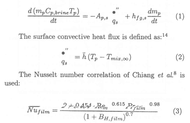
Based on the assumption that the mass and specific heat of the particle remain constant during a computational time-step, the governing differential equation can be discretised as:14
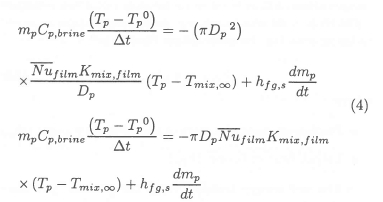
The governing differential equation for the enthalpy of the continuous phase contains source terms to account for sensible heat transfer between the continous and dispersed phases. These source terms are linearised and written as a function of the mixture enthalpy at infinity:15

after rearranging the discretised governing differential equation:

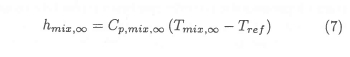
where the mixture enthalpy at infinity is defined as:
Mass transfer
The governing differential equation used to describe the interphase mass transfer between the gaseous phase and the dispersed phase is:10,13,14
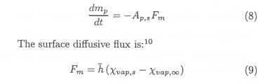
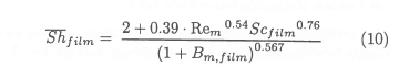
The Sherwood number correlation of Chiang et al.8is used:
The governing differential equation can be discretised, assuming a spherical particle geometry, as:
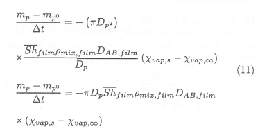
The mass of a particle, assuming a spherical particle geometry, is:

The mass transfer from the dispersed phase to the continuous phase is modelled as an enthalpy injection into the continuous phase. The enthalpy injection takes place on a computational "cell-by-cell" basis. Complete specification of the enthalpy injection into a cell requires the specification of:
• Mass injected
• Temperature of mass injected
• Specific heat of mass injected
However, at any particular moment many different particles may be traversing a particular cell. The degree of evaporation from each particle, the particle's temperature and the specific heat of the particle's vapour can vary from particle to particle, and from time-step to time-step in the case of a single particle. It is therefore necessary to calculate a representative value for the mass, temperature and specific heat of the matter injected into a particular cell. This is achieved by assuming that all discrete "packets" of mass injected into a cell, from whatever source, will be adiabatically mixed prior to injection. This concept is illustrated in Figure 2.

The process of adiabatic mixing requires:

The representative specific heat can be calculated as the mass-fraction weighted average of the contributions from each particle, at each time-step:

Momentum transfer
The governing differential equation used to describe the interphase momentum transfer between the gaseous phase and the dispersed phase takes into account drag forces and gravitational body forces:10,13,14
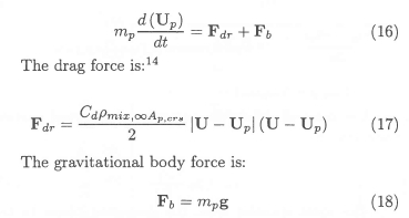
The drag coefficient correlation of Chiang et al.8 is used:

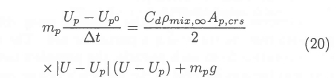
Assuming that a particle's mass remains constant during a computational time step, the governing differential equation (16) can be discretised as:
The governing differential equation for the momentum of the continuous phase contains source terms to account for interphase momentum transfer between the continuous and dispersed phases. These source terms are linearised and written as a function of the continuous phase velocity at infinity:5

after rearranging the discretised governing differential equation (20):

Particle freezing model
In the proposed desalination process, the feed water spray is injected into a high-vacuum flow field at a temperature in the range of 15°C to 25°C. Therefore, the spray particles tend to freeze as they vaporise. A simple model is used to describe the particle freezing process (Figure 3).
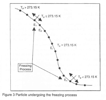
The particle continually cools down from its injection temperature until it reaches its freezing point temperature ( 273.15 K). At this point, the energy extraction required to bring about a complete phase change is:
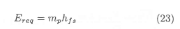
where:
• Particle mass at the start of the freezing process (mp)
• Latent heat of fusion (hfs)
The net energy transfer from the particle, per time step, is:

where: Length of computational time-step (∆t).
The total quantity of energy transferred from the particle, during the freezing process, is:

where: Number of computational time-steps elapsed during freezing process (n).
The completion condition of the particle freezing process is:

The particle freezing model only restricts the particle temperature to its freezing point during the freezing process; it does not modify the way in which the interphase heat transfer is calculated. On completion of the particle freezing process the particle continues to cool down as before.
Computational domain: Grid refinement
Due to limited computational resources, extensive use was made of non-adaptive grid refinement.14 Grid refinement was used in an attempt to:
• Adequately resolve the boundary layer regions
• Reduce cell distortion in the nozzle throat region
• Reduce cell distortion along the nozzle centre-line
• Accurately resolve the brine spray injected into the nozzle assembly.
Boundary conditions
Continuous phase boundary conditions
The continuous phase boundary conditions applied to the planar boundaries of the computational domain are:13,14,15
• Stagnation inlet condition applied to the nozzle inlet. This boundary condition specifies the stagnation properties: Total temperature and total pressure.16
• Prescribed pressure condition applied to the spray-section outlet. This boundary condition imposes a uniform static pressure distribution on the outlet plane of the flow domain.
• Symmetry planes applied to the tangential faces of the computational domain. This boundary condition allows the modelling of only a portion of the full tangential extent of the nozzle and spray-section assembly; it simply imposes a zero gradient on all variable components orthogonal to the symmetry boundary plane.
• Wall boundary condition applied to the inner surfaces of the nozzle and spray-section assembly. Wall functions are used to model the boundary layer velocity profile and impose a zero-slip condition.13 The walls are modelled as smooth and adiabatic.
Dispersed phase initial conditions
The brine injected into the spray-section portion of the nozzle assembly is modelled as an injected dispersed phase. Several assumptions are made in the calculation of the dispersed phase initial conditions. Computational parcels, representing a number of real droplets with similar initial conditions are used to approximate the behaviour of the large number of droplets encountered in the real brine spray. The initial orientation of the particle injection vectors vary randomly within the constraints of a spray orientation angle and a two-dimensional spray-cone angle. An injection volume, as opposed to an injection point, is used to introduce the computational parcels to avoid limitations imposed on the allowable cell volume fraction occupied by the dispersed phase.13 In addition, limits are placed on the minimum and maximum particle diameters used due to numerical accuracy and particle volume fraction limitations, respectively.14 The possible sensitivity of the supersonic flow to the manner in which the brine spray is introduced, requires that it be introduced in. such a manner as to cause as little disruption of the flow as possible.
In summary, the dispersed phase initial conditions are generated subject to the following constraints:
• Uniformly constant particle inlet temperature
• Uniformly constant particle density
• Uniformly constant particle inlet velocity magnitude
• Injection tangential velocity component (Uθ)of all particles is zero
• Radial (Ur) and axial (Uz) injection velocity components vary randomly within a spray orientation angle (a) and a two-dimensional spray cone angle (9)
• Overall brine mass injection rate (ṁp,tot) is specified • Total number of computational parcels (Np) is specified
• Initial particle diameters are normally distributed
• Initial particle positions are randomised within a specified starting volume.
Parametric tests
The simulation of the complex processes occurring in the nozzle and spray-section of the proposed desalination process require the specification of many variable values before a particular test case is uniquely defined. The main process variables are:
• Nozzle and spray-section geometry
• Continuous phase inlet stagnation pressure
• Pressure ratio applied over entire nozzle assembly
• Continuous phase inlet stagnation temperature
• Continuous/dispersed phase mass-flow-rate ratio
• Continuous and dispersed phase turbulent interaction
• Particle injection volume
• Orientation and cone angle of injected particle spray
• Initial particle diameter distribution
• Initial particle temperature
• Initial particle velocity magnitude
• Number of computational parcels.
A constant continuous-phase mass flow rate of one kilogram per second (1 kg/s) acts as a comparative foundation between the different parametric tests. The effects of the following variables, believed to have a significant influence on the degree of mass transfer from the brine spray, are numerically investigated:
• Pressure ratio applied over entire nozzle assembly in relation to the exit-to-throat diameter ratio of the nozzle
• Spray-section length
• Continuous/dispersed phase mass-flow-rate ratio
• Median particle diameter
• Number of computational parcels.
As the pressure ratio over the nozzle is varied, the exit-to-throat diameter ratio of the nozzle is calculated from the flow relations for quasi-one-dimensional isentropic flow of a calorically perfect gas through variable area ducts.16 The pressure ratios investigated are:
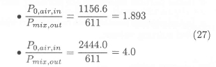
The first pressure ratio is derived from the expectation of the injected brine to tend to freeze (0°C) on exposure to the vacuum conditions in the spray section of the nozzle assembly, and the use of a 4°C oceanic heat sink with a 5°C heat exchanger temperature differential. The second pressure ratio increases the stagnation inlet pressure. These two pressure ratios correspond to two specific nozzle geometries termed Nozzle #1 and Nozzle #2.
The inlet stagnation temperature of the continuous phase is kept constant at 9°C on the assumed use of a heat exchanger (∆T ≈ 5°C) and oceanic heat sink (4°C).
Parametric test schedule
The specific values of the parametric variables investigated are shown in Tables 1 to 3.
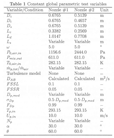
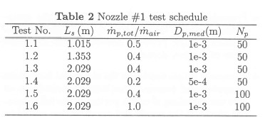
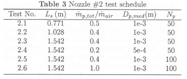
Table 2 and Table 3 list the actual values investigated, for the parameters listed as "variable" in Table 1.
Implementing the simulation within user subroutines
The simulation of the core desalination-process components was implemented within a variety of user-subroutines.12 The implementation of the dispersed-to-continuous phase enthalpy injection is also illustrated by McLaren.12
Conclusion: Simulation
Mathematical models for the interphase transfer of mass, momentum and energy have been presented. The interphase transfer models allow mutual coupled interaction between the continuous and dispersed phases. This interaction is implemented in an iterative manner in the solution algorithm of the CFD code.
A fundamental aspect of real fluid flow is the significant effect that turbulence can have on its overall behaviour. However, in the present study the effects of turbulence are neglected as this is a preliminary investigation of a conceptual idea.
Simulation results
The results of the investigation into the effects of the following parameters, on the degree of mass transfer from the brine spray, are presented:
• Pressure ratio applied over core component assembly
• Spray-section length
• Continuous/dispersed phase mass-flow-rate ratio
• Median particle diameter
• Number of computational parcels used.
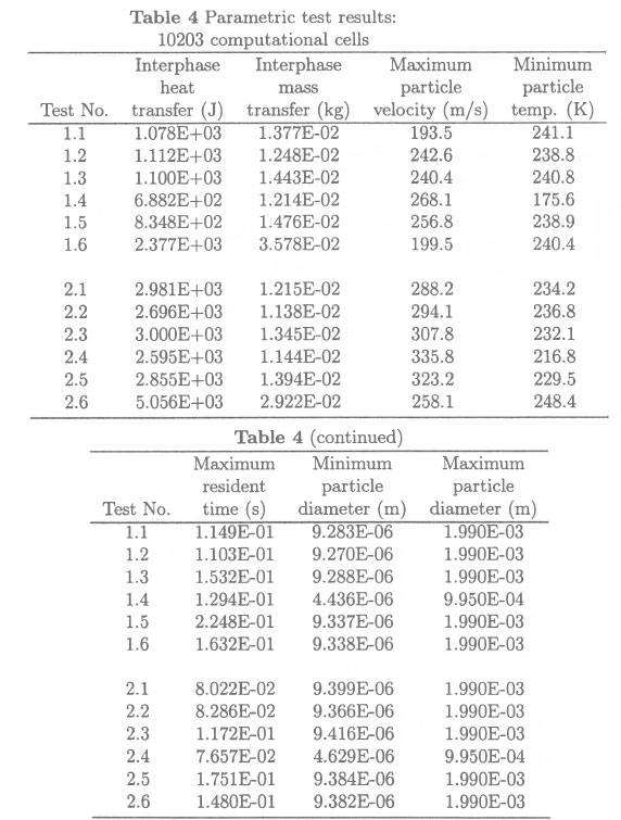
Tabulated results
The simulation results are presented in Table 4. These results should be interpreted with reference to the parametric test schedules shown in Tables 1 to 3.
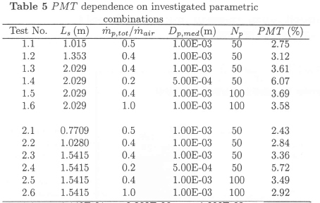
The primary dependent variable taken to indicate the relative effectiveness of the desalination process is the percentage mass transfer from the brine spray (PMT):

where: Total mass transfer from brine spray (δṁp,tot).
Table 5 indicates how the various combinations of the investigated parametric variable influence the percentage mass transfer (PMT).
Graphical results
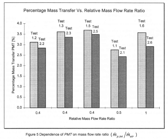
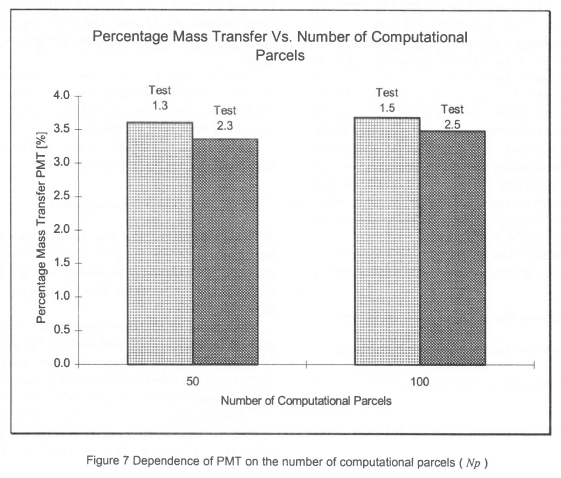
The graphs shown in Figures 4 to 7 indicate the relationships between the parametric variable combinations investigated and the percentage mass transfer (PMT). The following observations are made:
• Figure 4: It is to be expected that the PMT will exhibit some form of asymptotic behaviour with regard to the spray-section length as the brine spray should eventually saturate its immediate surroundings after sufficient mass transfer has taken place. This type of behaviour is indicated in Figure 4.
• Figure 5: This shows that the degree of mass transfer from the brine spray is small for most of the variable combinations investigated despite the fairly large variations in the investigated conditions.
• Figure 6: It is apparent that the median particle diameter or, put more generally, the particle diameter distribution has a significant influence on the degree of mass transfer from the brine spray. This dependence is consistent with the greater exposed surface area associated with a finer particle distribution.
• Figure 7: The number of computational parcels used in the parametric tests seem to be sufficient to represent the mass transfer behaviour of the brine spray. A doubling of the number of computational parcels used only produces a small change in the calculated mass transfer from the brine spray.


Conclusion: Results
The small percentage of mass lost by the brine spray is cause for concern. The low dispersed-to-continuous-phase mass flow ratio, in conjunction with the small degree of mass transfer, means that it would be necessary to maintain a substantial continuous phase mass flow for a relatively small output of desalinated water. Therefore the product water would be expensive in terms of unit energy consumption.
The injected dispersed phase tends to be rapidly accelerated by the continuous phase resulting in short particle residence times even if the nozzle assembly is physically large. This tends to prevent the saturation of the continuous phase, which would indicate that the maximum degree of interphase mass transfer has been achieved.
Due to combined sensible and latent heat transfer from the particles and the high latent heat of vaporisation of water, the internal energy of the brine droplets is insufficient to allow complete particle evaporation. Therefore, the degree of mass transfer from the brine spray is low. However, the mass transfer has shown a strong dependence on the particle size distribution. A future study using much smaller particle size distributions may indicate that greater degrees of mass transfer are possible.
One of the surprises of the present study is that the CFD code is able to correctly predict that the injected brine spray triggers an oblique shock wave cascade in the spray-section for transonic flow cases. In addition, indications are that normal shocks will tend to form in the expanding portion of the convergent-divergent nozzle when the brine mass injection rate approaches the continuous phase mass flow rate.
An immediately apparent problem is that the use of a very coarse computational mesh, due to limited computational resources, and lower order differencing schemes resulted in significant numerical smearing of the shock waves.
As far as the general interphase interactions are concerned, the smaller particle fractions are rapidly entrained within the continuous phase flow and reach high terminal velocities, whilst the larger particle fractions penetrate further into the free stream flow. The radial injection velocity component of the smaller particle fractions is rapidly reduced keeping them within, or in close proximity, to the spray-section boundary layer. The braking effect on the continuous phase of droplet entrainment results in a thickened boundary layer region. The sensible and latent heat transfer from the brine spray results in the spray-section boundary layer being rapidly heated. The number of computational parcels used to represent the brine spray, while initially thought insufficient, seem to be adequate to predict mass transfer from the brine spray.
Overall, the results of the various simulations are similar despite the fairly large range of conditions investigated.
Recommendations for future investigations
Future simulations should take the following into account:
• Direct particle-to-particle interactions (e.g. droplet coalescence)
• Particle break-up due to fluid dynamic forces and wall interactions
• Continuous phase turbulence and interphase turbulent interaction
• Accurate geometrical representation of real spray injection nozzles
• Mach number dependent models for interphase mass, momentum, and energy transfer.
The present two-dimensional simulation should be extended into three dimensions to take into account three-dimensional flow effects. A finer computational mesh, to increase spatial resolution, and higher order differencing schemes should be used to avoid numerical smearing of the oblique shock cascade. Extending the computational domain to model the supersonic diffuser attached to the spray-section would ease the problem of specifying appropriate boundary conditions on the spray-section outlet-plane.
An important component of future investigations should be a more comprehensive evaluation of the effects of the brine droplet size distribution on the degree of mass transfer from the brine spray.
Finally, a systematic design of the whole proposed desalination process is required.
Conclusion
A desalination process has been proposed and initially investigated by focusing on the core components of the process. The physical processes taking place in the core components are complex which has made their numerical simulation difficult.
A model of the core components of the desalination process has been developed and used to perform a number of parametric tests. These tests are used to numerically investigate the effects of a number of variables on the physical processes occurring within the core components.
Future research work should extend the simulation model to cope with a number of physical processes not taken into account in the present study. A future study of the entire proposed desalination process could lead to a full system design of the process, and a quantitative evaluation of its unit desalination cost.
References
1. ABCs of desalination. International Desalination Agency, 1997.
2. Hoffmann KA. Computational Fluid Dynamics for Engineers. Engineering Education Systems, 1989.
3. White FM. Fluid mechanics. McGraw Hill, 1986.
4. Versteeg HK, Malalasekera W. An introduction to Computational Fluid Dynamics. Longman Scientific & Technical, 1995.
5. Patankar SV. Numerical heat transfer and fluid flow. Hemisphere Publishing Corporation, 1980.
6. Sanders JPH, Sarh B, Gokalp I. Variable density effects in axisymmetric isothermal turbulent jets: a comparison between a first- and a second-order turbulence model. International Journal of Heat and Mass Transfer, 40, pp.823-842, 1997. [ Links ]
7. Kohnen G, Ruger M, Sommerfeld M. Numerical calculation of spray evaporation in turbulent flow. Proceedings of the International Symposium on Turbulence, Heat and Mass Transfer, Paper 10.1, 1994.
8. Chiang H, Raju MS, Sirignano WA. Numerical analysis of convecting, vaporizing fuel droplet with variable properties. International Journal of Heat and Mass Transfer, 35, pp. 1307-1324, 1992. [ Links ]
9. Young JB. The fundamental equations of gas-droplet multiphase flow. International Journal of Multiphase Flow, 21, pp. 175-191, 1995. [ Links ]
10. Crowe CT, Sharma MP, Stock DE. The particle-source-in cell (PSI-CELL) model for gas-droplet flows. Journal of Fluids Engineering, pp.325-332, 1977.
11. Saul A, Wagner W. A fundamental equation for water covering the range from the melting line to 1273 K at pressures up to 25 000 Mpa. Journal of Physical and Chemical Reference Data, 18, pp.1537-1564, 1989. [ Links ]
12. McLaren JR. An investigation into a desalination process based on dispersed multiphase flow through a transonic nozzle. Rand Afrikaans University, 1997.
13. Flo++ Ver. 2.14 User Manual. Softflo Incorporated. 1997.
14. Star-CD Ver. 2.30 User Manual. Computational Dynamics Limited, 1995.
15. Patankar SV. Numerical heat transfer and fluid flow. Hemisphere Publishing Corporation, 1980.
16. Anderson JD. Modern Compressible Flow. McGraw Hill, 1990.
17. Watkins AP. Three-dimensional modelling of gas flow and sprays in diesel engines. ASME Symposium on Automotive Engine Technology, 1987.
First received November 1999
Final version July 2001
