


Services on Demand
Article
 English (pdf)
 Article in xml format
 Article references
Indicators

Related links
-
 Cited by Google
 -
 Similars in Google
Share

 Permalink
Journal of the Southern African Institute of Mining and Metallurgy
On-line version ISSN 2411-9717
Print version ISSN 2225-6253
J. S. Afr. Inst. Min. Metall. vol.116 n.6 Johannesburg Jun. 2016
http://dx.doi.org/10.17159/2411-9717/2016/v116n6a7
PAPERS - COOPER COBALT AFRICA CONFERENCE
Corrosion of lead anodes in base metals electrowinning
A. MirzaI; M. BurrI; T. EllisI; D. EvansII; D. KakengelaII; L. WebbIII; J. GagnonIII; F. LeclercqIV; A. JohnstonIV
IRSR Technologies, Dallas, TX, USA
IICastle Lead Works, Krugersdorp, South Africa
IIIQuemetco Metals Limited, Inc., Casa Grande, AZ, USA
IVLe Plomb Francais, Estrees-Saint-Denis, France
SYNOPSIS
Lead-based alloys are used as the primary anodes for electrowinning from sulphate-based aqueous systems. Lead anode technology has evolved over the years, migrating from pure lead and lead-antimonial alloys to the present-day lead-calcium-tin alloys for copper electrowinning and lead-silver alloys for zinc electrowinning. Anode technology has also migrated from cast to rolled microstructures in search of improved mechanical properties and higher corrosion resistance. Although great strides have been made in the development of new alloys and production processes, the industry still has unresolved issues related to untimely corrosion, which limits anode life and may lead to higher contaminant levels in the metal being produced. Lead anodes corrode because of the difference in the chemical/electrochemical potential across the microstructural features of an anode. Given a very high purity material, we find that the grain boundary areas corrode significantly faster than the rest of the grain. A balance of alloying element selection and microstructural design allows the grain boundary area to be engineered, thus minimizing grain boundary corrosion. However, operational issues can lead to unexpected corrosion behaviours that we will discuss moving forward. The comments in this work, although directed toward copper electrowinning, can be extended to similar phenomena in other metals electrowon from sulphate media (i.e., zinc, nickel, cobalt, manganese). The life cycle of electrowinning anodes depends on tankhouse operating conditions and maintenance of the anodes, including cleaning and straightening. This paper will focus on the operational aspects of maximizing the utilization of lead anodes for base metals electrowinning.
Keywords: electrowinning, base metals, anode corrosion, anode technology
Introduction
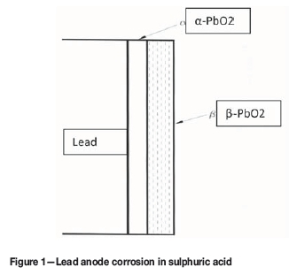
Lead-based alloys are the primary anodes used in electrowinning from sulphate-based aqueous systems. Lead anode technology has evolved over the years, migrating from pure lead and lead-antimonial alloys to the present-day lead-calcium-tin alloys for copper electrowinning and lead-silver alloys for zinc electrowinning (Prengaman, Ellis, and Mirza, 2010). Anode technology has also migrated from cast microstructure to mechanically deformed, rolled microstructures in search of improved mechanical properties and higher corrosion resistance that results from the rapid production of a protective oxide coating (Prengaman, 1987; Prengaman and Morgan, 1992, 2001). Although great strides have been made in the development of new alloys and production processes (Prengaman, 2000), the industry still has unresolved issues related to untimely corrosion which limits anode life and may lead to higher contaminant levels in the metal being produced. The comments in this work, although directed towards copper electrowinning, can be extended to similar phenomena in other metals electrowon from sulphate media (i.e., zinc, cobalt, nickel, manganese). The fundamental efficacy of lead-based anodes is dependent on the properties of PbO2 (Prengaman and McDonald, 1980). In fact, lead anodes are used predominantly in sulphate-based electrolyte systems because of the protective ability of PbO2. In particular, the protective adherent α-phase, which is the brown PbO2 layer closest to the anode surface, isolates the lead from the corrosive electrolyte. It is composed of large, rhombic, closely packed crystals. The β-phase of PbO2, which is black in colour, is the interface between the protective a-PbO2 and the electrolyte, as shown in Figure 1. It is composed of tetragonal, fine, loosely adhering needle-shaped crystals. The transformation of a-PbO2 to p-PbO2 is marked by formation of PbO, Pb(OH)2, PbSO4, and other complex sulphates as reaction intermediates. The mechanism of electrochemical oxidation of lead to lead dioxide in sulphuric acid is discussed in detail by Pavlov and Dinev (1980).
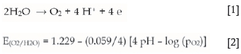
The oxidation of a lead anode is therefore determined not by the reaction rate of lead with sulphuric acid but by mass transport of the ions participating in the reaction through the electrochemical layer. The rate of oxidation decreases drastically with increasing thickness of the layer, and is prevented almost completely if the corrosion layer does not dissolve, flake off, or become porous (Hyvarinen, 1972). This mechanism renders the lead anode virtually inert in sulphate media, and the main reaction on the outer surface of the β-PbO2 layer becomes the electrochemical decomposition of water into molecular oxygen (Equation [1]):
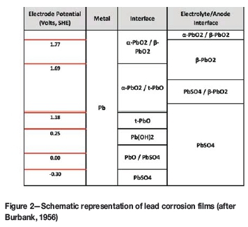
The first stage in lead oxidation in the presence of oxygen is the formation of lead monoxide (PbO) and lead sulphate (PbSO4). As the anode potential increases, the surface layer of PbO/PbSO4 transforms to Pb(OH)2, followed by conversion to the insulating tetragonal PbO, and then finally to PbO2 at higher potentials. As evident in Figure 2, it is necessary to maintain an anode potential above 1.77 V to maintain the protective a-PbO2. Unless the anode potential is consistently maintained above this value, the protective, adherent a-PbO2 converts to the loosely adherent p-PbO2 that flakes off and causes cathode contamination. This electrochemical layering effect explains the commercial success of lead-based anodes in sulphate media electrowinning in the last few decades.
Corrosion of lead anodes
A fundamental factor in anode corrosion is the difference in the chemical/electrochemical potential across the microstructural features of an anode. Given a very high purity material, we find that the grain boundary areas corrode significantly faster than the rest of the grain. Minimizing grain boundary corrosion by a balance of alloying element selection and microstructural design allows the grain boundary area to be engineered. However, operational issues can lead to unexpected corrosion behaviours, which we will discuss moving forward.
General corrosion
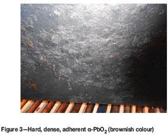
When a lead-based anode is exposed to a sulphate-based electrolyte, a thin film of PbSO4 is formed instantly. As soon as power is switched on, oxygen is evolved at the anode. The thin film of lead sulphate is then converted to p-PbO2. Upon further oxygen evolution, oxygen diffuses through β-PbO2 to form a-PbO2. The exact process during the oxidation of lead anode is determined by the structure and composition of the anode layer, which in turn is determined by the electrode potential as indicated in Figure 2. To produce the lowest lead content in the copper cathodes, lead anodes should be cleaned periodically to remove the loosely adherent portion of β-PbO2. The objective is not to remove all the β-PbO2 layers, but only the non-adhering layers with a pressure water wash. The typical surface of a cleaned lead anode in use with the adherent α-PbO2 is shown in Figure 3.
In order to increase the functional life of the anodes, it is extremely important not to damage the adherent protective -PbO2 layer during anode cleaning by being overly aggressive.
Chloride corrosion
While 20-30 mg/L Cl- in a copper electrowinning electrolyte is helpful for grain refining/levelling of the cathode deposits, higher chloride concentrations (>30 mg/L) increase corrosion of the Pb anodes due to the formation of soluble PbCl2 and other Pb chloride complexes. Pb chlorides are more soluble than PbO2 or PbSO4. A steady-state concentration of 55-60 mg/L chloride in the electrolyte is too high, and a concentration above 100 mg/L Cl- is highly deleterious for the anodes. Chloride also reacts with any MnO2 on the anode surface to form MnCl2. Higher levels of chloride (200-300 mg/L) are tolerated in zinc electrowinning because the much higher levels of manganese in the electrolyte form a thick protective layer of MnO2. High chloride levels in the electrolyte also enhance the corrosion of stainless steel cathodes.
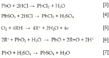
Chloride corrosion is highest at or above the solution line because the higher oxygen concentration at the surface enhances the formation of relatively soluble PbCl2 by Equations [3] and [4]. The mechanism of formation of PbO and PbSO4 in the presence of organics in the electrolyte via Equations [5] to [7] is explained in the section on Solution Line Corrosion.
In order to increase the functional life of lead anodes, it is imperative to keep chlorides levels in the copper electrowinning electrolyte below 20-30 mg/L.
Manganese-related corrosion
Copper electrowinning solutions often contain some manganese. It has been our customers' experience that at manganese concentrations above 40 mg/L in the electrolyte, manganese-related corrosion of lead anodes becomes significant. Problems related to manganese in the electrolyte have been discussed by Miller (1995) and Hughes et al. (1998). Cifuentes et al. (2005) investigated the effect of various impurities in a copper electrowinning electrolyte on the rate of corrosion of lead anodes and found that manganese increased the corrosion rate of lead anodes more significantly during normal tankhouse operation than during current interruptions.
Mechanism of manganese-related corrosion
The potential at the anode surface is high enough for Mn2+ in the electrolyte to oxidize to MnO2 and MnO4- at the anode according to Equations [8] to [10]:
The permanganate ion, MnO4, attacks PbO2 indirectly. It is first converted to MnO2 by the following reaction:

Equations [8] to [10] take place simultaneously on the anode, resulting in the formation of MnO2. Manganese in solution also reacts directly with the stable PbO2 corrosion layer on the anode surface to form MnO2:

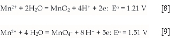
The PbSO4 formed in Equation [11] is also converted to PbO2 at the anode but it will be in the form of loose, non-adherent flakes. Under such circumstances, MnO2 and PbO2 crystals will also grow together forming large, fluffy flakes that spall easily, as illustrated in Figure 4. This not only results in cathode contamination but can also contribute to the formation of dendrites on cathodes.
The best solution, of course, is to prevent manganese from getting into the electrolyte in the first place. However, if the manganese content of the electrolyte is greater than 40 mg/L, it is important to clean the anodes regularly to minimize cathode contamination and maintain low power consumption. The periodicity of cleaning is unique for each tankhouse and should be established by experience. If tankhouse parameters such as current density, temperature, and manganese, iron, or chloride concentrations change, then the frequency of anode cleaning will have to re-determined. Once determined, it should be followed conscientiously.
Addition of 100-200 mg/L cobalt to the electrolyte helps in minimizing the deleterious effects of manganese-related corrosion. By decreasing the oxygen overpotential on the lead anode, cobalt in the electrolyte promotes oxygen evolution in preference to manganese oxidation. Above 200 mg/L, the cost/benefit ratio of adding cobalt decreases. Other measures to control manganese in copper electrowinning electrolyte are discussed in detail by Miller (1995). The literature alludes to using Fe/Mn ratios between 5 and 10 to alleviate manganese attack of Pb anodes. The extent to which iron helps depends on the relative rates of reaction of Fe2+ to Fe3+ and of Mn2+ to MnO2. This is determined by several factors, such as temperature, mass transport, acid concentration, etc.
Permanganate, MnO4-, being a powerful oxidant, degrades the solvent extraction reagents. Therefore, copper tankhouses have to sometimes add iron deliberately to decrease the formation of MnO4-.
Hanger bar corrosion
The main reasons for hanger bar corrosion are:
Electrolyte-hanger bar contact
Corrosion by copper sulphate
Electrolyte penetration
Ineffective anode design.
Electrolyte-hanger bar contact
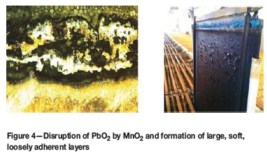
The electrolyte level is sometimes raised to overflow the electrolyte in order to float off the entrained organics. Electrolyte can also seep up to the hanger bars through the mist control foam or plastic balls by capillary action. If electrolyte is allowed to come in intimate contact with the hanger bars, as shown in Figure 5, copper will react spontaneously with H2SO4 to form CuSO4.5H2O. The exposed portion of the copper hanger bar between the end of the lead covering and the attachment to the busbar is corroded rapidly. To increase the functional life of lead anodes, it is therefore important not to immerse the hanger bars in the electrolyte and not to allow the level of plastic balls or the mist suppressant foam to be within 8-10 mm of the hanger bars.
When the hanger bar corrodes rapidly, it becomes weak and is no longer structurally sound. This is a safety issue during anode lifting and transport by crane for cleaning. It also causes the anodes to tilt, changing the anode-cathode spacing across the cell, with several ramifications as discussed in the section on Uneven Electrode Spacing.
Corrosion by copper sulphate
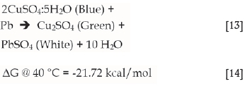
In covered copper tankhouses, acid rains down constantly on the anodes. As shown in Figure 5, copper reacts with sulphuric acid to form cupric sulphate (CuSO4.5H2O). However, what is not obvious is that cupric sulphate reacts spontaneously with lead to form cuprous sulphate [C%(SO4)2]:
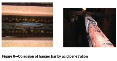
Electrolyte penetration
This type of corrosion is illustrated in Figure 6 and is most prevalent in covered copper tankhouses. Corrosion of lead by copper sulphate could weaken the integrity of the lead coating and allow penetration of the acid into the area between the protective lead encapsulation and the copper bar. This results in the formation of a significant amount of copper sulphate underneath the lead covering the hanger bar. Expansion upon crystallization of copper sulphate forces the lead away from the copper bar. This process becomes iterative, resulting in an eventual splitting of the lead castaround, as shown in Figure 6. Local and independent concentration cells are also set up in the region between the lead castaround and copper hanger bar, causing the copper to be corroded rapidly.
Ineffective anode design
Anode design is a crucial yet often overlooked or undervalued aspect of anode life optimization. Anode design is an important consideration in cathode plating efficiency. If the anode hanger bar is moved closer to the solution line in an effort to minimize the size of the lead anode, various modes of anode damage follow, owing to both electrochemical and mechanical reasons.
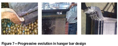
Corrosion stems from the exposed copper bar's proximity to the electrolyte level and from the presence of hoods for acid mist control. The captured acid mist runs down the hood and drops onto the exposed copper bar. With effective design, protection is extended to such vulnerable areas of the hanger bar. Figure 7 demonstrates the 'evolution' of anode hanger bar encapsulation design (from left to right).
In order to combat hanger bar corrosion in covered tankhouses and prolong anode life, the hanger bar needs to be completely coated with lead and the hanger bars must be washed often to prevent build-up of copper sulphate.
Solution line corrosion
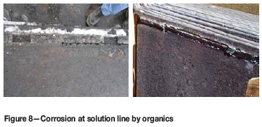
Solution line corrosion is often mistaken for weld corrosion where the weld line in welded anodes corresponds with the solution level. However, solution line corrosion, such as shown in Figure 8, is sometimes observed on rolled/slotted and cast anodes where a weld line is absent. If there is carryover of organics into the electrolyte from the solvent extraction process, the organics can cause solution line corrosion and can sometimes literally burn at the solution line.
Mechanism ofsolution line corrosion Formation of free radicals:
These surface-active polar molecules concentrate at the aqueous-organic interface at the solution line and react with the protective PbO2 as follows.
Free radical attack on protective a-PbO2 to form unprotective PbO:
Reaction of PbO with H2SO4 to form PbSO4

The PbSO4 formed is converted to PbO2 at the anode but it will be in the form of loose, non-adherent flakes. Since no alloy currently exists that can protect the anode, the only suitable action is to prevent organics from entering the tankhouse. To minimize solution line corrosion, the organics from the solvent extraction process must be removed from the electrolyte before it reaches the tankhouse. Column flotation, sand filters, or scavenger cells can be used for this purpose (Kordosky, 2002). Electrowinning cells should be split into scavenger and production cells to minimize organic carryover from the solvent extraction plant (Beukes and Badenhorst, 2009). Improved mixer-settler design enhances the distribution of the dispersion exiting the mixer and minimizes organic entrainment. In the case of settlers, it is essential to provide for sufficient flotation time to float the organics. Other means employed in the tankhouses include scrubbing and surface vacuuming. None of these methods are ideal because anodes will be exposed to organic attack, even if only the anodes in the scavenging section of the tankhouse.
Miscellaneous tankhouse issues
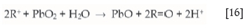
Uneven electrode spacing
The electrode spacing should be as consistent as possible. Figure 9 indicates that this is not always the case in a tankhouse. The inter-electrode spacing in copper tankhouses is usually about 10 cm. Below this spacing, the risk of shorts due to electrode alignment and dendritic growth of nodules becomes unacceptably high. If a dendrite touches the anode, the protective PbO2 becomes overheated, is softened, and spalls off under conditions of intense turbulence caused by oxygen evolution. This process is autocatalytic and blows holes through the anode. Therefore, to increase the useful life of lead anodes and to decrease power consumption, it is important to maintain uniform anode-cathode spacing and monitor and eliminate the shorts as soon as they are formed.
The potential of the electrowinning cell is the sum of respective half-cell reaction potentials as well as the ohmic drop in the electrolyte, busbars, and other competing electrochemical reactions. The ohmic drop in the electrolyte is a function of the electrode spacing, ionic mobility, concentration of the species in solution, and current density. Non-uniform electrode spacing adversely affects current distribution, power consumption, current efficiency, cathode contamination, and plating quality.
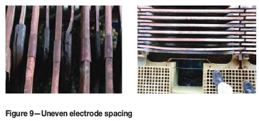
Copper plating on lead anodes
Strangely enough, copper sometimes deposits on lead anodes, as shown in Figure 10. This happens due to two reasons:
Dendrites
Power outage.
Dendrites
The local area where the dendrite touches the anode will become cathodic and copper will therefore deposit on the anode in this area. More importantly however, the protective a-PbO2 in the region around the dendrite will be reduced to PbSO4 which will flake off under conditions of intense oxygen evolution in the surrounding areas. This autocatalytic process will continue unabated until the dendrite blows a hole through the anode.
Power outage
Copper also plates on the lead anode if there is a power outage and if the anodes and cathodes are left electrically connected in the tankhouse electrolyte. This is also found to be a very common problem in cast Pb-Sb anodes compared with rolled Pb-Ca-Sn anodes. This is because cast anodes have segregation and casting defects, such as porosities and inclusions, which lead to non-uniform electrochemistry. As a result, there are areas in a cast anode that become relatively anodic to other areas more easily. On the other hand, rolled microstructure is very uniform with no casting defects, which results in uniform electrochemical behaviour across its surface.
Temperature fluctuations
Lead anodes should be protected from temperature fluctuations of the electrolyte. Due to differences in the coefficients of thermal expansion between the lead anode and PbO2 on the surface of the anode, a rapid drop in electrolyte temperature of about 10°C may result in spalling of the PbO2 layer from all the anodes in a tankhouse simultaneously. Electrolyte temperature fluctuations of a few degrees are not uncommon in tankhouses, but a sudden cold weather front can result in the electrolyte temperature dropping 10°C or more, especially in open tankhouses. An electrolyte heating system will prevent rapid fluctuations in temperature.
Addition ofcobalt
The main purpose of cobalt addition to copper electrowinning electrolyte is to depolarize the oxygen evolution reaction on a lead anode. This decreases the oxygen evolution overpo-tential and results in power savings. In other words, cobalt promotes the evolution of oxygen from the anode surface rather than corrosion of lead. Cobalt also protects the lead anode from corrosion and cathode copper from lead contamination. The adsorbed CO2+ ions on the lead anode hinder the penetration of oxygen into the PbO2 lattice, thus decreasing the rate of PbO2 formation and making the oxide layer thin and dense. The adsorbed cobalt ions also harden the oxide layer and make it less subject to spalling. Cobalt concentrations of 100-200 mg/L are common in copper tankhouses around the world. The exact level of cobalt is dependent on the manganese content, current density, and the electrolyte bleed rate, and has to be determined experimentally for each tankhouse. If any of these tankhouse parameters change significantly, then a new optimum cobalt concentration would have to be established, and once determined, maintained at this level. Cobalt is also lost from the system with the bleed stream. A drop in the cobalt content for several days may cause the cobalt to desorb from the anode surface, softening the flakes and increasing the likelihood of lead contamination of the cathode. Therefore, cobalt must be metered in continuously to the electrolyte to replace the cobalt that is lost through the bleed. Cobalt is a significant operating cost to copper solvent extraction-electrowinning operations.
Summary
The different types of corrosion processes described that effect lead anodes are by no means exhaustive but typical of those encountered in practice. Lead alloys are the preferred material for electrowinning anodes from acidic sulphate solution because they are insoluble and have the ability to form a protective PbO2 layer. They are corrosion resistant, economical, and have an acceptable operating voltage. There are alternative anode technologies, but none can compete economically with lead anodes. Moreover, limited long-term industrial test work has been carried out with the alternative anodes to prove their technical, practical, and commercial viability. Rolled Pb-Ca-Sn anodes are used widely in copper electrowinning. They are strong, have a particularly high corrosion resistance, good form stability, and have a low potential drop between the hanger bar and the lead sheet. The electrochemical performance of lead anodes is independent of whether they are made from primary or secondary lead. If the anodes are maintained properly according to the broad guidelines discussed in this paper, we can expect an optimum functional life.
References
Beukes, N.T. and Badenhorst, J. 2009. Copper electrowinning: theoretical and practical design, Proceedings of Southern African Hydrometallurgy 2009. Southern African Institute of Mining and Metallurgy, Johannesburg. pp. 213-240. [ Links ]
Burbank, J. 1956. Anodization of lead in sulphuric acid. Journal of the Electrochemical Society, vol. 103, no. 2. pp. 87-91. [ Links ]
Cifuentes, L., Astete, E., Crisóstomo, G., Simpson, J., Cifuentes, G., and Pilleux, M. 2005. Corrosion and protection of lead anodes in acidic copper sulphate solutions. Corrosion Engineering Science and Technology, vol. 40, no. 4. pp. 321-327. [ Links ]
Hughes, C., Barnard, K., Cheng, C.Y., and Larcombe, K. 1998. The role of contaminants in phase separation during copper solvent extraction. Proceedings of the ALTA Copper Hydrometallurgy Forum, Brisbane, Australia. [ Links ]
Hyvarinen, O. 1972. The effect of silver and cobalt on the oxygen evolution at lead anodes. Laboratory of Process Metallurgy, Helsinki University of Technology, Otaniemi, Finland. [ Links ]
Kordosky, G.A. 2002. Copper recovery using leach/solvent extraction/electrowinning technology: forty years of innovation, 2.2 million tonnes of copper annually. Journal of the South African Institute of Mining and Metallurgy, vol. 102. pp. 445-450. [ Links ]
Miller, G. 2010. Methods of managing manganese effects on copper SX-EW operations. Proceedings of ALTA 2010 Ni-Co-Cu Conference, Perth, Australia. [ Links ]
Miller, G. 1995. The problems of manganese and its effects on copper SX-EW operations. Copper 95 - Cobre 95, Electrorefining and Hydrometallurgy of Copper, vol. 3. Cooper, W.C., Dreisinger, D.B., Dutrizac, J.E., Hein, H., and Ugarte, G. (eds.). Canadian Institute of Mining, Metallurgy and Petroleum, Montreal. pp. 649-663. [ Links ]
Pavlov, D. and Dinev, Z. 1980. Mechanism of the electrochemical oxidation of lead to lead dioxide electrode in H2SO4 solution. Journal of the Electrochemical Society, vol. 127, no. 4. pp. 855-863. [ Links ]
Prengaman, R.D. 1987. New insoluble lead anodes for copper electrowinning. The Electrorefining and Winning of Copper. Proceedings of the TMS 116th Annual Meeting. Hoffman, J.E., Bautista, R.G., Ettel, V.A., Kudryk, V., and Wesely, R.J. (eds). The Minerals, Metals and Materials Society, Warrendale, PA. pp. 387-401. [ Links ]
Prengaman, R.D. 2000. Electrowinning anode. US patent 6,131798. RSR Technologies, Dallas, TX. [ Links ]
Prengaman, R.D., Ellis, T., and Mirza, A. 2010. 10 years' experience with rolled lead-calcium-silver anodes. Proceedings of Lead-Zinc 2010. Siegmund, A., Centomo, I., Geenen, C., Piret, N., Richards G., and Stephens, R. (eds.). The Minerals, Metals and Materials Society, Warrendale, PA. pp. 819-837. [ Links ]
Prengaman, R.D. and McDonald, H.B. 1980. Stable lead dioxide anode and method for production. US patent 4,236,978. RSR Corporation, Dallas, TX. [ Links ]
Prengaman, R.D. and Morgan, C.E. 1992. Electrowinning anode and method of manufacture. US patent 5, 172,850. RSR Corporation, Dallas, TX. [ Links ]
Prengaman, R.D. and Morgan C.E. 2001. Electrowinning anodes which rapidly produce a protective oxide coating. US patent 6,224,723 B1. RSR Technologies, Dallas, TX. [ Links ] ♦
This paper was first presented at the, Copper Cobalt Africa Conference, 6-8 July 2015, Avani Victoria Falls Hotel, Victoria Falls, Livingstone, Zambia.

